

Hitachi ZW 65-6-75-6-95-6 Wheel Loader Workshop+Service+Engine+Hydraulic Circuit Manual
FILE DETAILS:
Hitachi ZW 65-6-75-6-95-6 Wheel Loader Workshop+Service+Engine+Hydraulic Circuit Manual
This Listing includes all of the manuals mentioned below:
1.Hitachi Deutz D 2.9 L4 TD 2.9 L4 TCD 2.9 L4 Workshop Manual
2.Hitachi ZW 65 75 95 Main Harness Electrical Hydraulic Circuit Diagram
3.Hitachi ZW65-6 75-6 95-6 Wheel Loader Service Manual
4.Hitachi ZW65-6 75-6 95-6 Wheel Loader Workshop Manual
DESCRIPTION:
Hitachi ZW 65-6-75-6-95-6 Wheel Loader Workshop+Service+Engine+Hydraulic Circuit Manual
FOREWORD:
VALIDITY:
This Workshop Manual contains information and rules of conduct for technicians and authorised Hitachi service technicians of the wheel loader ZW75-6. Read this Workshop Manual carefully before commencing maintenance and repair work. Store the Workshop Manual for the responsible technicians at a central point where it is always accessible. In accordance with current usage in the industry, the term wheel loader is used in this Workshop Manual .
This Workshop Manual applies, in conjunction with the operating manual and the service manual, only to the Wheel loader ZW75-6.
This Workshop Manual applies to:
• Technical personnel
• authorised Hitachi service technicians (See page 6: Authorised Mecalac Service
Technicians)
TABLE OF CONTENTS:
Hitachi ZW 65-6-75-6-95-6 Wheel Loader Workshop+Service+Engine+Hydraulic Circuit Manual
- Hitachi Deutz D 2.9 L4 TD 2.9 L4 TCD 2.9 L4 Workshop Manual
Foreword
General
Safety information I User information
3.1 General
3.2 Specifications
3.3 Operating manual and workshop manual
3.4 Job cards
3.5 Explanation of symbols
Job card overview
5.1 Sorted alphabetically
5.2 Sorted numerically
Job cards
Special tools
- Hitachi ZW65-6 75-6 95-6 Wheel Loader Service Manual
1 Notes for the Reader 5
11 Validity 5
12 Illustrations 5
13 Accentuated text 5
131 Pictograms 5
132 Safety Note 6
133 Safety instructions 6
134 Warning notes 7
135 Guideline 7
2 Description 9
21 Parts of the wheel loader 9
22 Front section 10
221 Overview 10
222 Hydraulic hoses 10
23 Cab – interior 11
231 Multi-function panel 11
232 Display 11
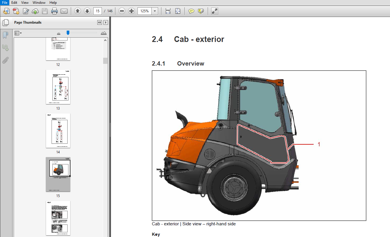
24 Cab – exterior 15
241 Overview 15
242 Central electrical system 16
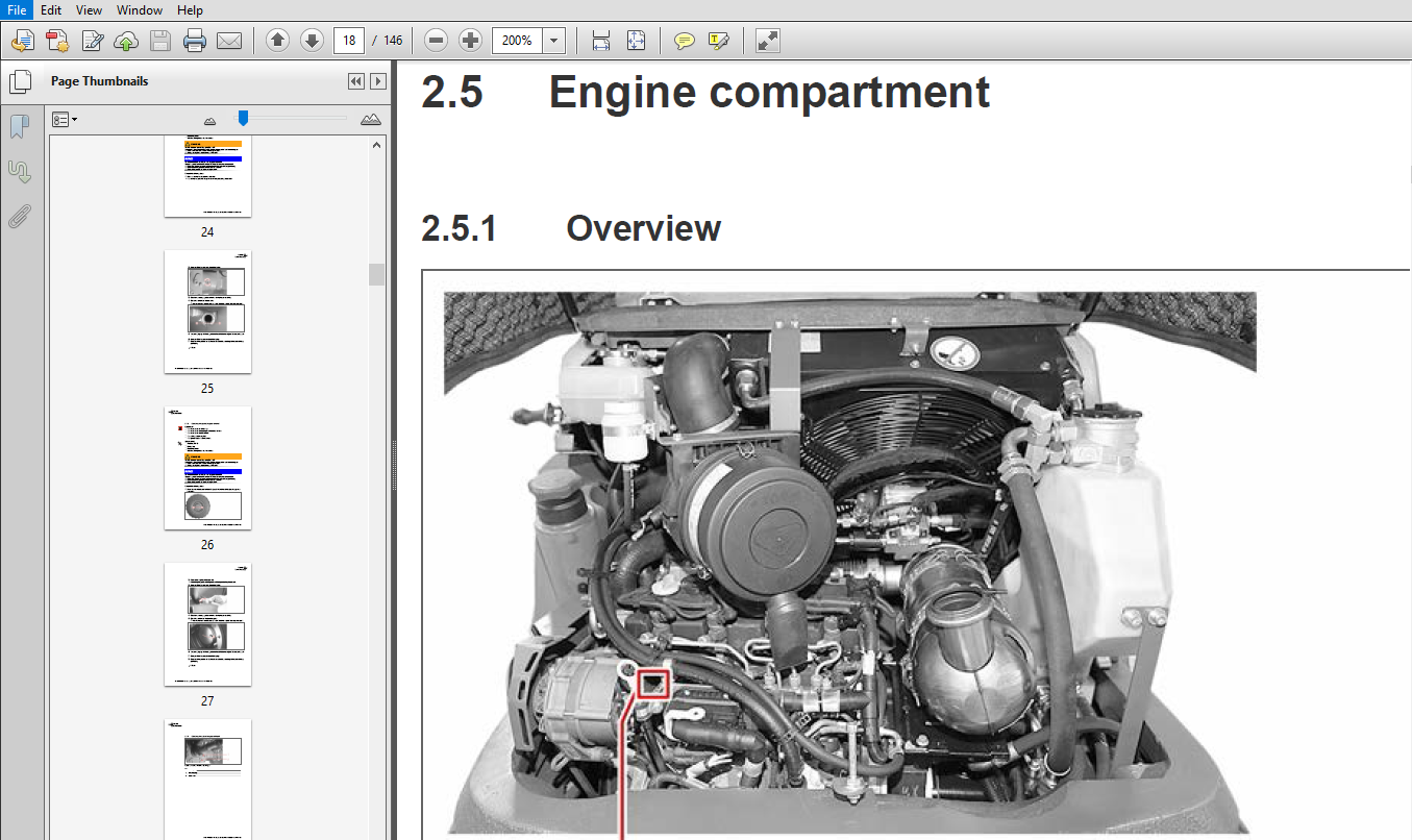
25 Engine compartment 18
251 Overview 18
252 Diagnosis interface – engine control system 18
26 Diagnostic unit 19
261 Overview 19
262 Error messages 20
3 Service tasks 21
31 Checks 21
311 Checking the front axle oil level 21
312 Checking the rear axle oil level 24
313 Checking the planetary gear oil level 26
314 Checking the reduction gear oil level 28
315 Checking the electrical functions and connections 30
316 Checking the hydraulic hoses 30
32 Repair work 31
321 Changing a wheel 31
322 Changing the V-belt 34
323 Changing the fuel pre-filter 38
324 Changing the fuel filter 41
325 Changing the fresh air filter 43
326 Changing the hydraulic fluid filter 44
327 Changing the engine oil filter 47
328 Changing the air filter 49
33 Changing the consumables 54
331 Changing the engine oil 54
332 Changing the gearbox oil of the front axle 57
333 Changing the gearbox oil of the rear axle 61
334 Changing the gearbox oil of the planetary gear 64
335 Changing the gearbox oil of the reduction gear 67
336 Refilling with diesel fuel 71
34 Lubrication 73
341 Lubrication plan 73
342 Lubrication points – engine hood 73
343 Lubrication points – doors 74
4 Circuit diagrams75
5 Annex 77
51 Spare Parts 77
511 Filter 77
512 Consumables 78
52 Deutz error messages 78
- Hitachi ZW65-6 75-6 95-6 Wheel Loader Workshop Manual
1 Notes for the Reader 6
11 Validity 6
12 Authorised Mecalac Service Technicians 6
13 Illustrations 6
14 Accentuated text 7
141 Pictograms 7
142 Safety Note 7
143 Safety instructions 7
144 Warning notes 8
145 Guideline 8
2 Technical Data 9
21 ZW 65-6 9
211 Equipment 9
212 Noise emission and vibration 9
213 Engine 9
214 Drive 10
215 Permissible tyres 10
216 Brake system 10
217 Steering 10
218 Hydraulic system 11
219 Performance data 11
2110 Dimensional drawing 11
2111 Filling capacities of the consumables 12
22 ZW 75-6 13
221 Equipment 13
222 Noise emission and vibration 13
223 Engine 13
224 Drive 14
225 Permissible tyres 14
226 Brake system 14
227 Steering 15
228 Hydraulic system 15
229 Performance data 15
2210 Dimensional drawing 15
2211 Filling capacities of the consumables 16
23 ZW 95-6 17
231 Equipment 17
232 Noise emission and vibration 17
233 Engine 18
234 Drive 18
235 Axle loads 18
236 Permissible tyres 18
237 Brake system 19
238 Steering 19
239 Hydraulic system 19
2310 Performance data 19
2311 Dimensional drawing 20
2312 Filling capacities of the consumables 21
3 Axles 23
4
ZW 65-6 75-6 95-6 Workshop Manual 11122015 23133595 0 SERIES GB
4 Hydraulic systems 25
41 Valves and hydraulic cylinders 25
411 Control valve 26
412 Steering 27
413 Priority valve30
414 Hydraulic cylinder 33
42 Hydraulic plan 42
43 Supply line plan 44
431 Hydraulic operating system 44
432 Steering hydraulic system 46
433 Hydraulic attachment locking device 47
434 Brake hydraulic system 48
435 Differential 49
436 Fan hydraulic system 51
5 Hydrostatic drive53
51 Basic knowledge 54
52 Pump A4VG 55
521 Basic knowledge 55
522 Overview 55
53 PC valve – pressure cut-off 57
531 Overview 57
532 Function of the PC valve 58
533 Design of the PC valve58
534 Mode of action58
535 Cross section of the PR valve 59
54 Setting points of the hydrostatic drive 61
541 Setting points of the A4VG pump 61
542 Setting point of the A6VM HD motor 62
55 Checking and setting the hydrostatic drive 63
551 Overview 63
552 Checking and setting supply pressure 63
553 Setting the mechanical zero point of the pump 65
56 Checking the setting 65
561 Checking the control start65
562 Checking the high- and control pressure66
57 Checking and setting the HP valve 66
571 Checking the HP valve 66
572 Setting the HP valve67
573 Bypass function – A4VG 71 – 180 68
574 HP relief valve 69
58 Hydrostatic drive A4VG-A6VM 70
581 Checking 70
582 Starting up 71
59 Pressure measuring point of the A4VG variable motor 71
591 Overview 71
592 Required equipment 72
510 Pressure measuring point on variable motor A6VM HA 73
5101 Overview 73
5102 Required equipment 74
511 A6VM HA Shuttle nozzle 74
5111 Overview 74
5112 Setting 76
512 Drive train troubleshooting 77
5121 Safety regulations77
5122 Checking and setting 79
5123 A4VG DA / A6VM HA 80
6 Electrical system 91
61 Basic knowledge 91
62 CAN bus-based E-system in the ZW T3b 91
63 CAN bus technology 92
631 CAN bus System ZW 92
632 Mecalac controller “U01” 93
633 Deutz engine controller “U5” 95
634 ALGA Matrix EVO “U06” 97
635 Diagnostic port 99
64 Ground levels 101
65 Main components / Block diagram 101
651 Relay board (PCB), “U15” 101
652 Deutz engine controller 104
653 Mecalac drive controller 106
654 Display 106
66 Current flow documentation 109
661 Example of “K50” power relay 109
662 Example of “JS02” right-hand control lever 110
663 Main circuit 111
67 List of components 113
68 Harnesses 117
681 Harness overview 117
682 Central harness 118
683 Harness – Steering 129
684 Harness – Front 132
685 Harness – Rear 136
686 Harness – Cab 146
7 System 149
71 Environmentally-friendly hydraulic fluids for axial piston machines 149
711 Synthetic hydraulic fluids 149
712 Permissible data 149
713 Conversion 150
72 Tightening torques 150
721 Screws 150
722 Slotted – castellated nuts 151
723 Wheel nuts 152
724 Castellated nuts on ball studs 153
73 Hydraulic drive 155
731 Test protocol ZW 65-6 75-6 95-6 155
732 Settings 158
74 Tipping special tools 163
75 Axles 165
VIDEO PREVIEW OF THE MANUAL:

IMAGES PREVIEW OF THE MANUAL:

PLEASE NOTE:
- This is the SAME exact manual used by your dealers to fix your vehicle.
- The same can be yours in the next 2-3 mins as you will be directed to the download page immediately after paying for the manual.
- Any queries / doubts regarding your purchase, please feel free to contact [email protected]


