

Hitachi Zaxis 800 Excavator Operation Principle+Troubleshooting+Workshop Manual
FILE DETAILS:
Hitachi Zaxis 800 Excavator Operation Principle+Troubleshooting+Workshop Manual
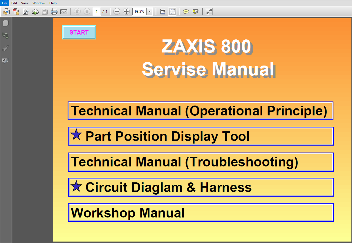
This Listing includes all of the manuals mentioned below:
- Hitachi Zaxis 800 Hydraulic Excavator Operational Principle Technical Manual
- Hitachi Zaxis 800 Hydraulic Excavator Troubleshooting Technical Manual
- Hitachi Zaxis 800 Hydraulic Excavator Workshop Manual
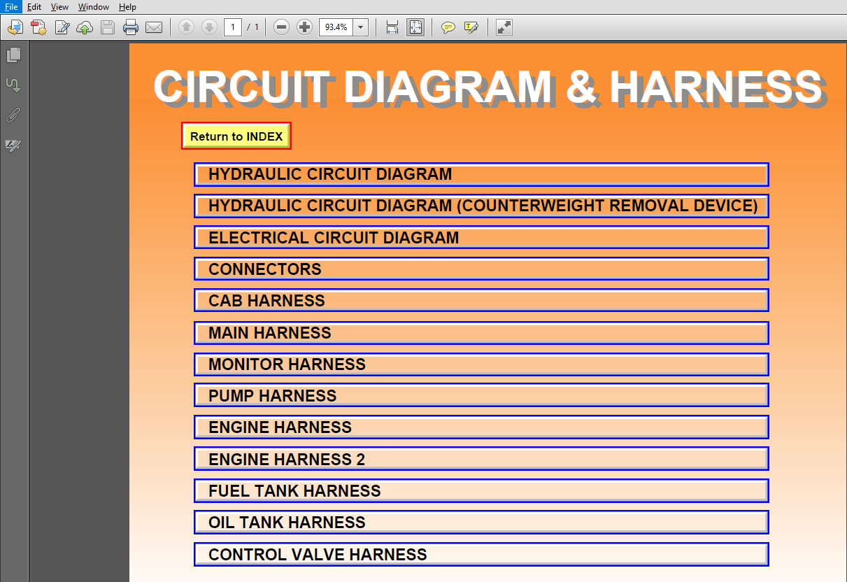
- Hitachi Zaxis 800 Hydraulic Excavator Circuit Diagram & Harness
- Hitachi Zaxis 800 Hydraulic Excavator Part Position Display Tool
DESCRIPTION:
Hitachi Zaxis 800 Excavator Operation Principle+Troubleshooting+Workshop Manual
INTRODUCTION:
TO THE READER:
• This manual is written for an experienced technician to provide technical information needed to maintain and repair this machine.
• Be sure to thoroughly read this manual for correct product information and service procedures.
• If you have any questions or comments, at if you found any errors regarding the contents of this manual, please contact using “Service Manual Revision Request Form” at the end of this manual.
ADDITIONAL REFERENCES:
• Please refer to the materials listed below in addition to this manual.
• The Operator’s Manual
• The Parts Catalog
• The Engine Manual
• Parts Catalog of the Engine
• Hitachi Training Material
MANUAL COMPOSITION:
• This manual consists of three portions: the Technical Manual (Operational Principle), the Technical Manual (Troubleshooting) and the Workshop Manual.
• Information included in the Technical Manual (Operational Principle): technical information needed for redelivery and delivery, operation and activation of all devices and systems.
• Information included in the Technical Manual (Troubleshooting): technical information needed for operational performance tests, and troubleshooting procedures.
• Information included in the Workshop Manual: technical information needed for maintenance and repair of the machine, tools and devices needed for maintenance and repair, maintenance standards, and removal/installation and assemble/ disassemble procedures.
TABLE OF CONTENTS:
Hitachi Zaxis 800 Excavator Operation Principle+Troubleshooting+Workshop Manual
- Hitachi Zaxis 800 Hydraulic Excavator Operational Principle Technical Manual
SECTION 1
GENERAL
Group 1 Specification
SpecificationsT1-1-1
Working RangesT1-1-3
Group 2 Component Layout
Main Components Layout T1-2-1
Electrical Component Layout (Overview) T1-2-2
Electrical System (Rear Deck) T1-2-3
Electrical System (Around Battery) T1-2-4
Electrical System (Pressure Sensor) T1-2-4
Electrical System
(Monitors and Switches) T1-2-5
EngineT1-2-6
Pump DeviceT1-2-7
Swing Device T1-2-7
Control ValveT1-2-8
Solenoid Valve
(Swing Preference Circuit) T1-2-8
Solenoid Valve Unit T1-2-8
Travel Device T1-2-9
Counterweight Removal Device
(Optional) T1-2-9
Group 3 Component Specifications
EngineT1-3-1
Engine Accessories T1-3-4
Hydraulic Component T1-3-5
Electrical Component T1-3-7
SECTION 2
SYSTEMSECTION 3
COMPONENT OPERATION
—CONTENTS—
Group 1 Pump Device
Outline T3-1-1
Main PumpT3-1-2
Regulator T3-1-4
Pilot PumpT3-1-12
N Sensor (Engine Speed Sensor) T3-1-12
Pump Delivery Pressure Sensor T3-1-12
Pump Displacement Angle Sensor T3-1-12
Group 2 Swing Device
Outline T3-2-1
Swing Reduction GearT3-2-2
Swing Motor T3-2-3
Swing Parking Brake T3-2-4
Valve UnitT3-2-6
Group 3 Control Valve
Outline T3-3-1
Hydraulic Circuit T3-3-6
Flow Combiner ValveT3-3-10
Main Relief ValveT3-3-11
Overload Relief Valve T3-3-12
Make-Up ValveT3-3-12
Holdding Valve T3-3-13
Arm Regenerative Valve T3-3-14
Bypass Shut-Out ValveT3-3-16
Boom Overload Relief Selector Valve T3-3-18
Group 4 Pilot Valve
Outline T3-4-1
Operation T3-4-2
Group 5 Travel Device
Outline T3-5-1
Travel Reduction GearT3-5-2
Travel Motor T3-5-3
Travel Brake Valve T3-5-5
Travel Speed ControlT3-5-10
Parking BrakeT3-5-12
Group 6 Signal Control Valve
Outline T3-6-1
Pilot Port T3-6-2
Shuttle Valve T3-6-6
Shockless Valve T3-6-8
Pump 1 and Pump 2 Flow Rate
Control Valves T3-6-10
Flow Combiner Valve Control Spool,
Swing Parking Brake Release Spool T3-6-12
Group 7 Others (Upperstructure)
Pilot Shut-Off Valve T3-7-1
Solenoid Valve Unit T3-7-2
Pilot Relief Valve T3-7-2
Accumulator T3-7-3
EC MotorT3-7-4
Group 8 Others (Undercarriage)
Swing Bearing T3-8-1
Center JointT3-8-2
Track Adjuster T3-8-3
Group 1 Control System
Outline T2-1-1
Engine Control T2-1-2
Pump Control T2-1-15
Valve ControlT2-1-30
Other ControlsT2-1-41
Group 2 Hydraulic System
Outline T2-2-1
Pilot CircuitT2-2-2
Main Circuit T2-2-12
Counterweight Removal Circuit T2-2-20
Group 3 Electrical System
Outline T2-3-1
Main Circuit T2-3-2
Electric Power Circuit (Key Switch: OFF)T2-3-3
Indicator Light Check Circuit
(Key Switch: ON) T2-3-4
Accessory Circuit T2-3-5
Preheat Circuit (Key Switch: Heat)T2-3-6
Starting Circuit (Key Switch: Start)T2-3-8
Charging Circuit (Key Switch: ON) T2-3-10
Serge Voltage Prevention Circuit T2-3-14
Engine Stop CircuitT2-3-16
- Hitachi Zaxis 800 Hydraulic Excavator Troubleshooting Technical Manual
ECTION 4
OPERATIONAL
PERFORMANCE TEST
Group 1 Introduction
Operational Performance Tests T4-1-1
Preparation for Performance
Test T4-1-2
Group 2 Standard
Operational Performance
Standard Table T4-2-1
Main Pump P-Q Diagram T4-2-4
Injection Pump T4-2-5
DrEX Monitor Indicating Values T4-2-6
Sensor Activating Range T4-2-11
Group 3 Engine Test
Engine Speed T4-3-1
Engine Compression Pressure T4-3-3
Valve Clearance T4-3-4
Nozzle Check T4-3-6
Injection Timing T4-3-8
Group 4 Excavator Test
Travel Speed T4-4-1
Track Revolution Speed T4-4-2
Mistrack Check T4-4-3
Travel Motor Leakage T4-4-4
Swing Speed T4-4-5
Swing Function Drift Check T4-4-6
Swing Motor Leakage T4-4-7
Maximum Swingable
Slant Angle T4-4-8
Swing Bearing Play T4-4-9
Hydraulic Cylinder Cycle Time T4-4-10
Dig Function Drift Check T4-4-11
Control Lever Operating Force T4-4-12
Control Lever Stroke T4-4-13
Boom Raise/Swing Combined
Operation Check T4-4-14
Group 5 Component Test
Primary Pilot Pressure T4-5-1
Secondary Pilot Pressure T4-5-3
Main Relief Pressure Shift Control
Pressure(SA Pressure) T4-5-4
Travel Mode Shift Control
Pressure(SB Pressure) T4-5-5
Boom Mode Selector Control
Pressure(SC Pressure) T4-5-6
Main Pump Delivery Pressure T4-5-7
Main Relief Pressure T4-5-8
Overload Relief Valve Set Pressure T4-5-12
Main Pump Flow Rate Measurement T4-5-14
Swing Motor Drainage T4-5-18
Travel Motor Drainage T4-5-20
Group 6 Adjustment
Installation and Adjustment
of Pump Displacement Sensor T4-6-1
Engine Speed Adjustment and
Engine Learning T4-6-2
Check of Governor Lever and
Fuel Cut Lever Position T4-6-4
SECTION 5
TROUBLESHOOTING
CONTENTS
Group 1 General
Introduction T5-1-1
Diagnosing Procedure T5-1-2
Built-In Diagnosing System Operation T5-1-4
Built-In Diagnosing Function Display List T5-1-5
Dr EX Operation T5-1-6
Dr EX Fault Code List T5-1-7
Dr EX Monitoring Item List T5-1-8
Dr EX Special FunctionT5-1-10
Dr EX Service Mode T5-1-13
Adjustment Data List T5-1-24
Binary Number List T5-1-27
Group 2 Component Layout
Main Component LayoutT5-2-1
Electrical Component Layout (Overview) T5-2-2
Electrical System
(Rear Deck) T5-2-3
Electrical System
(Around Battery) T5-2-4
Electrical System
(Pressure Sensor) T5-2-4
Electrical System
(Monitors and Switches) T5-2-5
EngineT5-2-6
Pump DeviceT5-2-7
Swing Device T5-2-7
Control ValveT5-2-8
Solenoid Valve
(Swing Preference Circuit) T5-2-8
Solenoid Valve Unit T5-2-8
Travel Device T5-2-9
Counterweight Removal / Device
(Option) T5-2-9
Components in Control Valve T5-2-10
Signal Control Valve
Port Location T5-2-14
Group 3 Troubleshooting A
Troubleshooting A Procedure T5-3-1
Fault Code List T5-3-2
Fault Code 01, 02, 03 T5-3-3
Fault Code 04T5-3-3
Fault Code 05T5-3-3
Fault Code 06T5-3-4
Fault Code 07T5-3-5
Fault Code 08, 09T5-3-6
Fault Code 10, 11 T5-3-7
Fault Code 12, 13T5-3-8
Fault Code 14, 15, 16, 18 T5-3-9
Fault Code 19T5-3-10
Fault Code 20, 21T5-3-11
Group 4 Troubleshooting B
Troubleshooting B Procedure T5-4-1
Relationship between Machine Trouble
Symptoms and Related PartsT5-4-2
Correlation between Trouble
Symptoms and Part FailuresT5-4-16
Engine System Troubleshooting T5-4-27
All Actuator System Troubleshooting T5-4-42
Front Attachment System
Troubleshooting T5-4-48
Swing System TroubleshootingT5-4-58
Travel System TroubleshootingT5-4-61
17PT-5-2
Other System Troubleshooting T5-4-68
Work After Replacing ComponentsT5-4-86
Add Compressor Oil T5-4-86
Charge Air Conditioner with
Refrigerant T5-4-87
Exchange Inspection T5-4-95
Group 5 Troubleshooting C
Troubleshooting C Procedure T5-5-1
Malfunction of Coolant
Temperature GaugeT5-5-2
Malfunction of Fuel Gauge T5-5-4
Malfunction of Indicator Light
Check System T5-5-6
Malfunction of Preheat Indicator T5-5-7
Malfunction of Engine Oil Level
Indicator T5-5-8
Malfunction of Coolant Level
Indicator T5-5-10
Malfunction of Alternator Indicator T5-5-12
Malfunction of Engine Oil Pressure
Indicator T5-5-14
Malfunction of Overheat Indicator T5-5-16
Malfunction of Air Filter Restriction
Indicator T5-5-18
Malfunction of Buzzer T5-5-20
Malfunction of LCDT5-5-22
Malfunction of Hour Meter T5-5-23
Group 6 Electrical System Inspection
Precautions for Inspection and
MaintenanceT5-6-1
Instructions for Disconnecting
ConnectorsT5-6-3
Fuse InspectionT5-6-4
Fusible Link InspectionT5-6-5
Battery Voltage Check T5-6-5
How to Troubleshoot Alternator
Malfunctions T5-6-6
Continuity Check T5-6-7
Voltage and Current Measurement T5-6-8
Check by False Signal T5-6-11
Test Harness T5-6-12
Group 7 ICX
Outline T5-7-1
ICX Fault Code List T5-7-6
Satellite Terminal Fault Code List T5-7-6
Fault Code 1 to 6T5-7-7
Fault Code 7 to 10T5-7-7
Some Parts of Data in Daily Report,
Frequency Distribution, Cumulative
Operation Hours are not Recorded T5-7-8
Troubleshooting and Setting of ICX and
Satellite Terminal Using Dr EX T5-7-10
Satellite Communication System T5-7-11
- Hitachi Zaxis 800 Hydraulic Excavator Workshop Manual
SECTION 1
GENERAL INFORMATION
Group 1 Precautions for Disassembling
and Assembling
Precautions for Disassembling and
AssemblingW1-1-1
Maintenance Standard TerminologyW1-1-7
Group 2 Tightening Torque
Tightening Torque Specification W1-2-1
Torque Chart W1-2-3
Piping Joint W1-2-6
Periodic Replacement of Parts W1-2-10
Group 3 Painting
Painting W1-3-1
SECTION 2
UPPERSTRUCTURE
Group 1 Cab
Remove and Install CabW2-1-1
Dimensions of the Cab GlassW2-1-7
Remove and Install Cab GlassW2-1-9
Group 2 Counterweight
Remove and Install Counterweight W2-2-1
Remove and Install Counterweight
(with Counterweight Removal Device) W2-2-3
Group 3 Main Frame
Remove and Install Main Frame W2-3-1
Group 4 Pump Device
Remove and Install Pump DeviceW2-4-1
Disassemble Pump TransmissionW2-4-6
Assemble Pump Transmission W2-4-8
Disassemble Main Pump W2-4-10
Assemble Main Pump W2-4-14
Maintenance Standard W2-4-18
Disassemble Regulator W2-4-20
Assemble RegulatorW2-4-22
Disassemble and Assemble Pilot
Pump W2-4-24
Group 5 Control Valve
Remove and Install Control Valve W2-5-1
Disassemble Control Valve
(5-Spool Section)W2-5-4
Assemble Control Valve
(5-Spool Section)W2-5-10
Disassemble Control Valve
(4-Spool Section)W2-5-16
Assemble Control Valve
(4-Spool Section)W2-5-22
Disassemble Control Valve
(Side Section) W2-5-28
Assemble Control Valve
(Side Section) W2-5-32
Disassemble HousingW2-5-34
Assemble HousingW2-5-36
Disassemble Manifold W2-5-38
Assemble Manifold W2-5-40
Group 6 Swing Device
Remove and Install Swing Device W2-6-1
Disassemble Swing Device W2-6-4
Assemble Swing Device W2-6-12
Disassemble Swing Motor W2-6-20
Assemble Swing Motor W2-6-24
Maintenance StandardW2-6-28
Group 7 Pilot Valve
Remove and Install Pilot Valve W2-7-1
Disassemble Right and Left Pilot
Valves W2-7-8
Assemble Right and Left Pilot Valves W2-7-12
Disassemble Travel Pilot ValveW2-7-16
Assemble Travel Pilot Valve W2-7-20
Group 8 Pilot Shut-Off Valve
Remove and Install Pilot Shut-Off
Valve W2-8-1
Disassemble and Assemble Pilot Shut-Off
Valve W2-8-3
SECTION 3
UNDERCARRIAGE
Group 1 Swing Bearing
Remove and Install
Swing Bearing W3-1-1
Disassemble Swing Bearing W3-1-4
Assemble Swing Bearing W3-1-6
Group 2 Travel Device
Remove and Install Travel DeviceW3-2-1
Disassemble Travel DeviceW3-2-4
Assemble Travel DeviceW3-2-10
Disassemble Travel Motor W3-2-18
Assemble Travel Motor W3-2-22
Disassemble Brake Valve W3-2-28
Assemble Brake Valve W3-2-30
Maintenance Standard W3-2-32
Group 3 Center Joint
Remove and Install Center Joint W3-3-1
Disassemble Center Joint W3-3-4
Assemble Center Joint W3-3-6
Maintenance Standard W3-3-9
Group 4 Track Adjuster
Remove and Install Track AdjusterW3-4-1
Disassemble Track AdjusterW3-4-2
Assemble Track AdjusterW3-4-8
Group 5 Front Idler
Remove and Install Front IdlerW3-5-1
Disassemble Front IdlerW3-5-2
Assemble Front Idler W3-5-6
Maintenance StandardW3-5-10
Group 6 Upper and Lower Roller
Remove and Install Upper RollerW3-6-1
Remove and Install Lower RollerW3-6-4
Disassemble Lower Roller W3-6-8
Assemble Lower RollerW3-6-10
Maintenance StandardW3-6-12
Group 7 Track
Remove and Install Track W3-7-1
Maintenance StandardW3-7-7
SECTION 4
FRONT ATTACHMENT
CONTENTS
Group 1 Front Attachment
Remove and Install Front AttachmentW4-1-1
Remove and Install Bushing W4-1-8
Maintenance Standard W4-1-10
Standard Dimensions for
Arm and Bucket ConnectionW4-1-13
Standard Dimensions for
Arm and Boom Connection W4-1-14
Group 2 Cylinder
Remove and Install Cylinder W4-2-1
Hydraulic Circuit Pressure
Release ProcedureW4-2-10
Disassemble CylinderW4-2-12
Assemble Cylinder W4-2-16
Maintenance Standard W4-2-20
SECTION 5
ENGINE AND ACCESSORY
General Information
General Repair Instruction0A-1
Illustration Arrows0A-2
Abbreviations 0A-3
Nut and Bolt Angular Tightening Method0A-4
Standard Bolt Torque Specifications 0A-6
Recommended Thread Locking Agents 0A-8
Main Data and Specifications 0A-9
Engine External View Drawing 0A-11
Service Standard0A-12
Torque Specifications 0A-18
Special Tools0A-25
Troubleshooting0A-27
Lubricant Application 0A-37
Sealant Application0A-37
Service Information
Identification0B-1
Lubrication System0B-2
Fuel System 0B-2
Cooling System 0B-6
Valve Clearance Adjustment0B-6
Compression Pressure Measurement0B-8
Recommended Lubricants0B-9
Engine Oil Viscosity Chart 0B-9
Engine Mechanical
Service Precautions 6A-2
General Description6A-2
Fan Center 6A-4
Turbocharger6A-8
Exhaust Manifold6A-10
Inlet Manifold 6A-11
Water Pump 6A-14
Alternator 6A-16
Oil Cooler 6A-18
Injection Pump 6A-20
Coupling Assembly6A-24
Cylinder Head6A-27
Rocker Arm and Shaft Assembly 6A-47
Camshaft6A-52
Timing Gears6A-57
Flywheel Housing 6A-65
Oil Pan 6A-68
Piston6A-71
Crankshaft6A-86
Crank Pulley6A-97
Flywheel 6A-100
Cylinder Body 6A-102
Engine Cooling
Service Precautions6B-1
General Description6B-2
Water Pump 6B-3
Thermostat6B-8
Engine Fuel
Service Precautions 6C-1
General Description 6C-2
Fuel Filter 6C-5
Injection Nozzle Holder 6C-7
Injection Pump 6C-13
Starting and Charging
Service Precautions 6D3-1
Alternator 6D3-2
Starter Motor 6D3-11
17PW-5-2
Engine Lubrication
Service Precaution 6G-1
General Description 6G-2
Oil Pump 6G-4
Oil Coolor 6G-12
Main Oil Filter 6G-16
Partial Oil Filter 6G-19
Engine Induction
Service Precaution 6J-1
Turbocharger 6J-2
VIDEO PREVIEW OF THE MANUAL:

IMAGES PREVIEW OF THE MANUAL:
PLEASE NOTE:
- This is the SAME exact manual used by your dealers to fix your vehicle.
- The same can be yours in the next 2-3 mins as you will be directed to the download page immediately after paying for the manual.
- Any queries / doubts regarding your purchase, please feel free to contact [email protected]


