

Genie ZX-135/70 Service & Repair Manual 1279835 – PDF DOWNLOAD
Language : English
Pages : 258
Downloadable : Yes
File Type : PDF
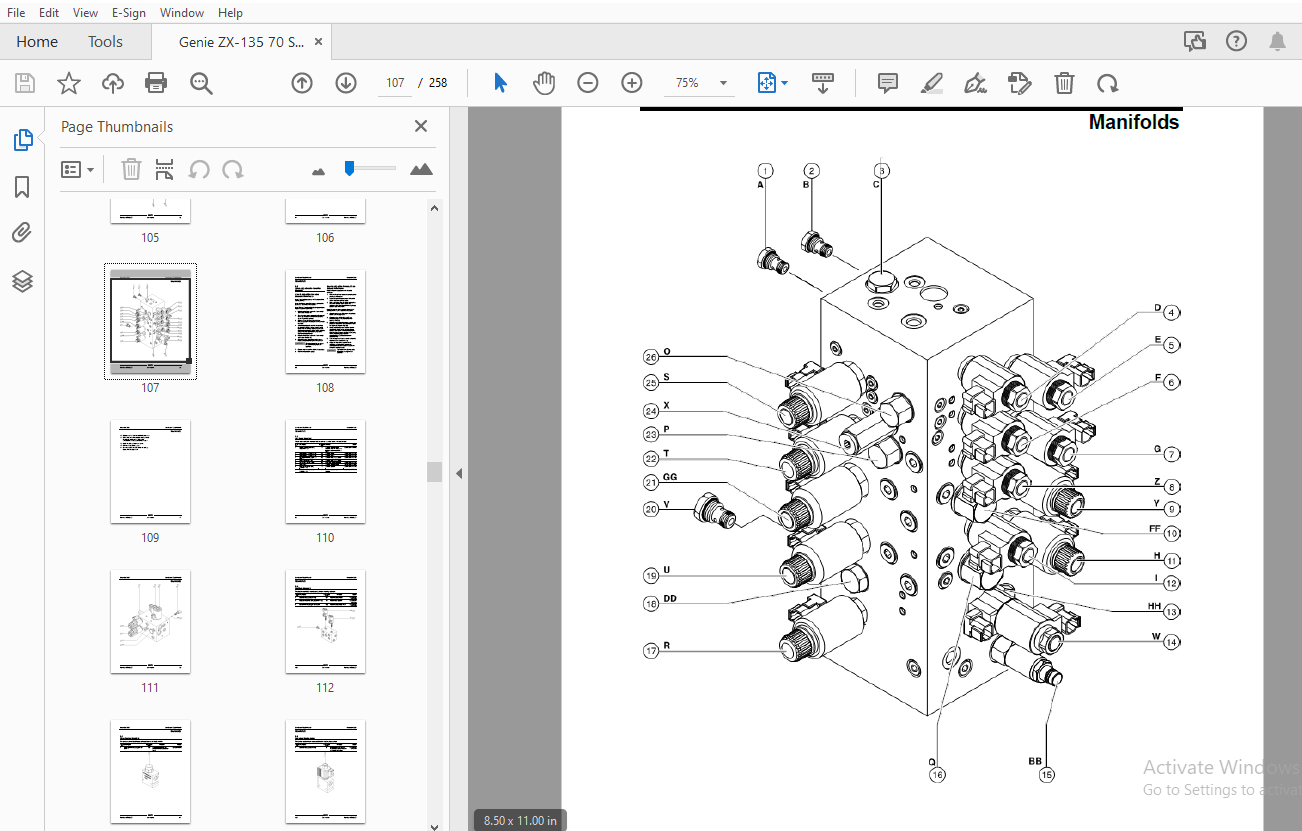
Table of Contents:
Genie ZX-135/70 Service & Repair Manual 1279835 – PDF DOWNLOAD
Front Cover...........................................................................................  1
Important Information.................................................................................  2
Find a Manual for this Model..........................................................................  2
Revision History......................................................................................  3
Serial Number Legend..................................................................................  4
General Safety Rules..................................................................................  5
Table of Contents.....................................................................................  7
Specifications........................................................................................ 13
	Machine Specifications............................................................................ 13
	Performance Specifications........................................................................ 13
	Hydraulic Oil Specifications...................................................................... 14
	Hydraulic Component Specifications................................................................ 16
	Deutz TD 2.9 Engine Specifications................................................................ 19
	Deutz TD2011L04i Engine Specifications............................................................ 20
	Deutz TCD 2.2 L3 Engine Specifications............................................................ 22
	Perkins 854F-34T Engine Specifications............................................................ 23
	Perkins 1104D-44T Engine Specifications........................................................... 25
	Machine Torque Specifications..................................................................... 27
	Hydraulic Hose and Fitting Torque Specifications.................................................. 28
Repair Procedures..................................................................................... 29
	Introduction...................................................................................... 29
	Platform Controls................................................................................. 31
		Platform Controls............................................................................. 31
		1-1 Platform Circuit Board.................................................................... 32
			How to Remove the LED Circuit Board....................................................... 33
		1-2 Joysticks - How to Calibrate a Joystick................................................... 33
			How to Reset a Proportional Valve Coil Default............................................ 37
			How to Set the Function Thresholds and Default Functions Speeds........................... 38
			How to Adjust the Function Speeds......................................................... 40
			How to Adjust the Function Ramp Rate Setting.............................................. 40
	Platform Components............................................................................... 41
		2-1 Platform.................................................................................. 41
		2-2 Platform Leveling Cylinder................................................................ 42
		2-3 Platform Rotator.......................................................................... 43
			How to Bleed the Platform Rotator......................................................... 44
		2-4 Platform Level Sensor - How to Calibrate the Platform Level Sensor........................ 45
		2-5 Platform Overload System.................................................................. 46
			How to Perform a Zero Load Platform Calibration........................................... 46
			How to Perform a Full Load Platform Calibration........................................... 47
			How to Replace the Platform Overload Load Cell............................................ 49
		2-6 Platform Overload Recovery Message........................................................ 50
	Jib Boom Components............................................................................... 52
		3-1 Jib Boom Cable Track...................................................................... 53
			How to Repair the Cable Track............................................................. 54
		3-2 Jib Boom.................................................................................. 55
		3-3 Jib Boom Lift Cylinder.................................................................... 57
		3-4 Jib Boom Level Cylinder................................................................... 58
		3-5 Jib Boom Extension Cylinder............................................................... 59
		3-6 Jib Boom Bellcrank Angle Sensor - How to Calibrate the Jib Boom Bellcrank Angle Sensor.... 60
	Boom Components................................................................................... 63
		4-1 Primary Boom Cable Track.................................................................. 64
			How to Repair the Primary Boom Cable Track................................................ 66
		4-2 Secondary Boom Cable Track................................................................ 66
			How to Repair the Secondary Boom Cable Track.............................................. 68
		4-3 Primary Boom.............................................................................. 69
		4-4 Primary Boom Lift Cylinder................................................................ 70
		4-5 Secondary Boom Lift Cylinder.............................................................. 71
		4-6 Primary Boom Extension Cylinder........................................................... 74
		4-7 Secondary Boom Extension Cylinders........................................................ 75
		4-8 Primary Boom Angle Sensor - How to Calibrate the Primary Boom Angle Sensor................ 76
		4-9 Secondary Boom Angle Sensor - How to Calibrate the Secondary Boom Angle Sensor............ 79
	Engines........................................................................................... 81
		5-1 RPM Adjustment............................................................................ 81
		5-2 Flex Plate................................................................................ 81
			How to Install the Flex Plate............................................................. 82
		5-3 Diesel Particle Filter Regeneration - Deutz TCD 2.2 L3.................................... 83
	Ground Controls................................................................................... 84
		6-1 Bypass/Recovery Key Switch................................................................ 84
			How to Use the Recovery Mode.............................................................. 86
		6-2 Circuit Boards............................................................................ 87
		6-3 Membrane Decal............................................................................ 89
		6-4 Full Machine Calibration.................................................................. 90
	Display Module.................................................................................... 91
	Hydraulic Pumps................................................................................... 99
		7-1 Function Pump............................................................................. 99
			How to Prime the Function Pump............................................................100
			How to Adjust the Function Pump Standby Pressure..........................................100
			How to Adjust the Function Pump Pressure Compensator......................................101
		7-2 Drive Pump................................................................................102
			How to Prime the Drive Pump...............................................................103
	Manifolds.........................................................................................104
		8-1 Function Manifold Components..............................................................104
		8-2 Valve Adjustments - Function Manifold.....................................................108
		8-3 Jib Boom Manifold.........................................................................110
		8-4 Platform Manifold.........................................................................112
		8-5 Flow Control Mainfold.....................................................................113
		8-6 Function Enable Valve.....................................................................114
		8-7 Turntable Rotation Manifold...............................................................115
		8-8 Steer and Axle Manifold...................................................................116
		8-9 Valve Adjustments - Steer and Axle Manifold...............................................120
		8-10 Traction Manifold Components.............................................................122
		8-11 Valve Adjustments - Traction Manifold....................................................126
		8-12 Generator Manifold Component.............................................................127
		8-13 Valve Coils..............................................................................128
	Turntable Rotation Components.....................................................................130
		9-1 Turntable Rotation Assembly...............................................................130
			How to Adjust the Turntable Rotation Gear Backlash........................................131
		9-2 Turntable Level Sensor - How to Calibrate the Turntable Level Sensor......................132
	Axle Components...................................................................................135
		10-1 Steer Sensors............................................................................135
			How to Calibrate a Replacement Steer Sensor...............................................137
			How to Calibrate All Steer Sensors........................................................138
		10-2 Steer Cylinders..........................................................................140
		10-3 Axle Extension Cylinders.................................................................140
		10-4 Axle Angle Sensors - How to Calibrate the Axle Angle Sensors.............................141
Fault Codes...........................................................................................144
	Introduction......................................................................................144
	Control System Fault Codes........................................................................145
	Fault Code Source.................................................................................163
	Fault Matrix......................................................................................166
	Deutz TCD 2.2 L3 Engine Fault Codes...............................................................167
	Deutz TD 2.9 L4 Engine Fault Codes................................................................177
	Perkins 854F-34T Engine Fault Code................................................................192
Schematics............................................................................................200
	Introduction......................................................................................200
	Wire Circuit Legend...............................................................................201
	Wire Color Legend.................................................................................205
	Limit Switches and Angle Sensors..................................................................210
	Circuit Connector Legend..........................................................................214
	Drive Chassis and Platform Controller Pin Legend..................................................217
	Safety Controller Pin Legend......................................................................219
	Turntable Controller Pin Legend...................................................................220
	VEC Module - Deutz TD2011L04i and Perkins 1104D-44T Models........................................222
	VEC Module - Deutz TD 2.9 L4 and TCD 2.2 L3 Models................................................223
	VEC Module - Perkins 854F Models..................................................................224
	Electrical Symbols Legend.........................................................................225
	Hydraulic Symbols Legend..........................................................................226
	Electrical Schematics.............................................................................227
		Perkins 1104D-44T Engine Electrical Schematic - View 1........................................228
		Perkins 1104D-44T Engine Electrical Schematic - View 2........................................229
		Perkins 854F-34T Engine Electrical Schematic - View 1.........................................232
		Perkins 854F-34T Engine Electrical Schematic - View 2.........................................233
		Perkins 854F-34T Engine Harness...............................................................236
		Deutz TCD 2.2 L3 Engine Harness...............................................................237
		Deutz TCD 2.2 L3 Engine Electrical Schematic - View 1.........................................240
		Deutz TCD 2.2 L3 Engine Electrical Schematic - View 2.........................................241
		Deutz TD 2.9 L4 Engine Electrical Schematic - View 1..........................................244
		Deutz TD 2.9 L4 Engine Electrical Schematic - View 2..........................................245
		Deutz TD 2.9 L4 Engine Harness................................................................248
		Elecrical Schematic - Contact Alarm...........................................................249
		Generator Wiring Diagram - ANSI / CSA.........................................................252
		Generator Wiring Diagram - AUS................................................................253
		Electrical Schematic..........................................................................257
	Hydraulic Schematics..............................................................................255
		Hydraulic Schematic...........................................................................256
Back Cover............................................................................................258
S.S 05/24


