

Doosan DX255LC-3 Excavator Shop Manual 950106-00374E – PDF DOWNLOAD
DESCRIPTION:
Doosan DX255LC-3 Excavator Shop Manual 950106-00374E – PDF DOWNLOAD
Serial Number 50001 and Up (Europe Only)
GENERAL :
Doosan DX255LC-3 Excavator Shop Manual 950106-00374E – PDF DOWNLOAD
DX255LC-3……………………………………………………………………………… 0
Table of Contents…………………………………………………………………… 7
Safety…………………………………………………………………………….. 9
Track Excavator Maintenance Safety SP002322………………………………………… 11
Safety Instructions………………………………………………………….. 15
Applicable Models……………………………………………………………. 15
Safety Messages……………………………………………………………… 16
Signal Words…………………………………………………………….. 16
Other Signal Words……………………………………………………….. 17
Safety Decals……………………………………………………………….. 17
General…………………………………………………………………….. 18
Safe Operation is Operator’s Responsibility…………………………………. 18
Know Your Machine………………………………………………………… 18
Proper Work Tools and Attachments………………………………………….. 18
Pressurized Fluids……………………………………………………….. 19
Flying or Falling Objects…………………………………………………. 20
Personal Protective Equipment (PPE)………………………………………… 20
Correction of Machine Problems…………………………………………….. 21
Crushing and Cutting……………………………………………………… 21
Hot Coolant and Oils – Burn Prevention……………………………………… 22
Fire and Explosion Prevention……………………………………………… 22
Fire Extinguisher and First-Aid Kit (Emergency Medical Kit)…………………… 26
Electrical System and Electrical Shock……………………………………… 26
Rollover Protective Structure (ROPS)……………………………………….. 27
Transportation………………………………………………………………. 30
Obey State and Local Over-the-Road Regulations………………………………. 30
Loading and Unloading…………………………………………………….. 30
Transporting Machine……………………………………………………… 31
Operation…………………………………………………………………… 32
Before Engine Starting……………………………………………………. 32
Work Site……………………………………………………………….. 33
Mounting/Dismounting……………………………………………………… 34
Cleaning………………………………………………………………… 35
Operator Station…………………………………………………………. 35
Seat Belt……………………………………………………………….. 36
Visibility Information……………………………………………………. 37
Boost Starting or Charging Engine Batteries…………………………………. 38
Starting Engine………………………………………………………….. 39
Swinging or Traveling…………………………………………………….. 40
Lifting and Digging………………………………………………………. 42
Operation on Slopes………………………………………………………. 43
Towing………………………………………………………………….. 44
Attachment………………………………………………………………. 45
Equipment Lowering with Engine Stopped……………………………………… 45
Engine Stop……………………………………………………………… 45
Parking Machine………………………………………………………….. 46
Preservation/Storing Machine………………………………………………. 47
Maintenance…………………………………………………………………. 49
Warning Tag……………………………………………………………… 52
Cleaning………………………………………………………………… 53
Proper Tools and Clothing…………………………………………………. 53
Disassembling Precautions…………………………………………………. 53
Use of Lighting………………………………………………………….. 54
Fire and Explosion Prevention……………………………………………… 54
Burn Prevention………………………………………………………….. 55
Rubber That Contains Fluorides…………………………………………….. 56
Rubber and Plastics………………………………………………………. 57
Welding Repairs………………………………………………………….. 58
Warning for Counterweight and Front Attachment Removal……………………….. 59
Lock Inspection Covers……………………………………………………. 60
Working on Machine……………………………………………………….. 60
Accumulator……………………………………………………………… 61
Compressed Air…………………………………………………………… 61
Track Tension Adjustments…………………………………………………. 62
Supports and Blocking for Work Equipment……………………………………. 62
High-pressure Lines, Tubes and Hoses……………………………………….. 63
Battery…………………………………………………………………. 64
Environment and Circumstances…………………………………………………. 66
Work Site Areas Requiring Extra Caution…………………………………….. 66
High-voltage Cables………………………………………………………. 68
Underground Operation…………………………………………………….. 69
Working in Water…………………………………………………………. 69
Working in Contaminated Environment………………………………………… 69
Operation in Extreme Conditions……………………………………………. 70
Exhaust Ventilation………………………………………………………. 74
Asbestos Information……………………………………………………… 74
Silica Dust Information…………………………………………………… 75
Disposal of Hazardous Materials……………………………………………. 75
Sound…………………………………………………………………… 76
Vibration……………………………………………………………….. 76
Specifications……………………………………………………………………… 77
Specifications for DX255LC-3 SP002547……………………………………………… 79
Safety Instructions………………………………………………………….. 83
Applicable Models……………………………………………………………. 83
General Description………………………………………………………….. 85
Component Locations………………………………………………………….. 86
General Dimensions…………………………………………………………… 88
One – Piece Boom…………………………………………………………. 88
Two – Piece Boom…………………………………………………………. 89
Working Range……………………………………………………………….. 90
One – Piece Boom…………………………………………………………. 90
Two – Piece Boom…………………………………………………………. 92
General Specifications……………………………………………………….. 94
Engine Performance Curves (Per KS-R1004 Standard)……………………………….. 96
Approximate Weight of Workload Materials……………………………………….. 98
Performance Tests…………………………………………………………….100
Excavator Performance Measurements……………………………………………..101
Test Conditions…………………………………………………………..101
Travel Speed and Travel Motor Balance (Steering Deviation) Tests……………….101
Swing Speed and Deceleration Force Test……………………………………..103
Cylinder Performance Tests…………………………………………………105
General Maintenance………………………………………………………………….107
General Maintenance Instructions SP002454…………………………………………..109
Safety Instructions…………………………………………………………..113
Applicable Models…………………………………………………………….113
Welding Precautions and Instructions……………………………………………114
Hydraulic System – General Precautions………………………………………….115
Maintenance Service and Repair Procedure………………………………………..117
General Precautions……………………………………………………….117
Hydraulic System Cleanliness and Oil Leaks………………………………………118
Maintenance Precautions for Hydraulic System Service………………………….118
Oil Leakage Precautions……………………………………………………119
Cleaning and Inspection……………………………………………………….120
General Instructions………………………………………………………120
Bearing Inspection………………………………………………………..121
Standard Torques SP002404…………………………………………………………129
Safety Instructions…………………………………………………………..133
Applicable Models…………………………………………………………….133
Torque Values for Standard Metric Fasteners……………………………………..134
Torque Values for Standard U.S. Fasteners……………………………………….135
Type 8 Phosphate Coated Hardware……………………………………………….137
Torque Values for Hose Clamps………………………………………………….138
ORFS Swivel Nut Recommended Torque……………………………………………..138
Torque Values for Split Flanges………………………………………………..139
Torque Wrench Extension Tools………………………………………………….140
Torque Multiplication……………………………………………………..140
Other Uses for Torque Wrench Extension Tools…………………………………141
Tightening Torque Specifications (Metric)……………………………………142
Upper Structure……………………………………………………………………..145
Cabin SP002324…………………………………………………………………..147
Safety Instructions…………………………………………………………..151
Applicable Models…………………………………………………………….151
Cabin Identification………………………………………………………….152
Rollover Protective Structure (ROPS)………………………………………..152
Removal……………………………………………………………………..154
Installation…………………………………………………………………158
Counterweight SP002548……………………………………………………………161
Safety Instructions…………………………………………………………..165
Applicable Models…………………………………………………………….165
General……………………………………………………………………..166
Warning for Counterweight and Front Attachment Removal………………………..166
Removal……………………………………………………………………..168
Installation…………………………………………………………………169
Fuel Tank SP002549……………………………………………………………….171
Safety Instructions…………………………………………………………..175
Applicable Models…………………………………………………………….175
General Description…………………………………………………………..176
Parts List……………………………………………………………….176
Specifications……………………………………………………………177
Removal……………………………………………………………………..178
Installation…………………………………………………………………182
Start-up Procedures…………………………………………………………..185
Fuel Transfer Pump (Option) SP002550……………………………………………….187
Safety Instructions…………………………………………………………..191
Applicable Models…………………………………………………………….191
General Description…………………………………………………………..192
Theory of Operation……………………………………………………….192
Troubleshooting………………………………………………………………194
Replacement of Rotor and Vane………………………………………………….194
Replacement of Rear Cover……………………………………………………..195
Replacement of Armature……………………………………………………….195
Swing Bearing SP002329……………………………………………………………197
Safety Instructions…………………………………………………………..201
Applicable Models…………………………………………………………….201
Swing Bearing Maintenance……………………………………………………..202
Operating Recommendation…………………………………………………..202
Measuring Swing Bearing Axial Play………………………………………….202
Measuring Bearing Lateral Play……………………………………………..202
Swing Bearing Basic Operation………………………………………………203
Disassembly………………………………………………………………203
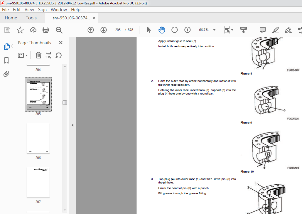
Assembly…………………………………………………………………205
Lower Structure and Chassis…………………………………………………………..207
Track Assembly SP002551…………………………………………………………..209
Safety Instructions…………………………………………………………..213
Applicable Models…………………………………………………………….213
General Description…………………………………………………………..214
Track Tension………………………………………………………………..215
Cleaning and Inspection (Wear Limits and Tolerances)……………………………..217
Track Shoe……………………………………………………………….218
Lower Roller……………………………………………………………..220
Upper Roller……………………………………………………………..221
Front Idler………………………………………………………………222
Track Shoes and Links…………………………………………………………223
Track Removal…………………………………………………………….223
Track Installation………………………………………………………..224
Front Idler Roller……………………………………………………………225
Parts List……………………………………………………………….225
Front Idler Roller Disassembly……………………………………………..226
Front Idler Roller Reassembly………………………………………………228
Lower Roller…………………………………………………………………230
Parts List……………………………………………………………….230
Lower Roller Removal………………………………………………………231
Lower Roller Disassembly…………………………………………………..231
Lower Roller Reassembly……………………………………………………232
Lower Roller Installation………………………………………………….233
Upper Roller…………………………………………………………………234
Parts List……………………………………………………………….234
Upper Roller Removal………………………………………………………235
Upper Roller Disassembly…………………………………………………..235
Upper Roller Reassembly……………………………………………………237
Track Spring and Track Adjusting Cylinder……………………………………….238
Parts List……………………………………………………………….238
Engine and Drivetrain………………………………………………………………..241
Engine Coolant Heater (Option) SP002328…………………………………………….243
Safety Instructions…………………………………………………………..247
Applicable Models…………………………………………………………….247
Disassembly and Assembly………………………………………………………248
Changing the Circulating Pump………………………………………………248
Changing the Temperature Limiter……………………………………………250
Changing the Temperature Sensor…………………………………………….251
Changing the Combustion Air Fan…………………………………………….253
Changing the Burner, Flame Monitor and Glow Plug……………………………..255
Changing the Burner Head…………………………………………………..257
Changing the Heat Exchanger………………………………………………..259
Drive Coupling (Main Pump) SP002586………………………………………………..261
Safety Instructions…………………………………………………………..265
Applicable Models…………………………………………………………….265
Drive Coupling……………………………………………………………….266
Special Tools………………………………………………………………..267
Installation of Drive Coupling…………………………………………………268
Installation Procedure…………………………………………………….270
Hydraulics………………………………………………………………………….271
Hydraulic System Troubleshooting, Testing and Adjustment SP002597……………………..273
Safety Instructions…………………………………………………………..277
Applicable Models…………………………………………………………….277
Hydraulic System – General Notes……………………………………………….278
Hydraulic Schematic…………………………………………………………..279
General Notes…………………………………………………………….279
Operation of Working Components………………………………………………..281
Boom Operating Circuit…………………………………………………….281
Boom Up Circuit…………………………………………………………..281
Boom Down Circuit…………………………………………………………281
Arm Operating Circuit……………………………………………………..282
Arm Crowd Circuit…………………………………………………………282
Arm Dump Circuit………………………………………………………….282
Bucket Operating Circuit…………………………………………………..283
Bucket Crowd Circuit………………………………………………………283
Bucket Dump Circuit……………………………………………………….283
Swing Operating Circuit……………………………………………………283
Right Swing Operating Circuit………………………………………………284
Left Swing Operating Circuit……………………………………………….284
Swing Relief Valve and Makeup Valve…………………………………………284
Travel Operating Circuit…………………………………………………..284
Forward Travel Circuit…………………………………………………….285
Reverse Travel Circuit…………………………………………………….285
Procedural Troubleshooting Baseline Recommendations………………………………286
Initial Checks and Tests to Establish Operating Condition of the Excavator………286
Pilot Pressure……………………………………………………………….288
Adjustment and Testing…………………………………………………….288
Power Mode Valve……………………………………………………………..289
Current Signal and Hydraulic Pressure Adjustments…………………………….289
Pressure Up Valve…………………………………………………………….290
Checks and Adjustments…………………………………………………….290
Pump Input Power Control………………………………………………………292
Pump Regulator Adjustment………………………………………………….292
Flow Meter and Flow Meter Kit Installation and Testing……………………………295
Swing System Troubleshooting…………………………………………………..297
Precautions/Initial Checks…………………………………………………297
Swing Relief Valve Checking and Adjustment…………………………………..298
Troubleshooting – Swing Gearbox………………………………………………..300
Troubleshooting – Hydraulic Problems……………………………………………301
Troubleshooting – Control Valve………………………………………………..303
Troubleshooting – Travel Control Valve………………………………………….304
Troubleshooting – Joystick Control Valve………………………………………..305
Accumulator SP002455……………………………………………………………..307
Safety Instructions…………………………………………………………..311
Applicable Models…………………………………………………………….311
General Description…………………………………………………………..312
Specifications……………………………………………………………314
Center Joint (Swivel) SP002456…………………………………………………….315
Safety Instructions…………………………………………………………..319
Applicable Models…………………………………………………………….319
General Description…………………………………………………………..321
Parts List……………………………………………………………….322
Troubleshooting, Testing and Adjustment…………………………………………323
Inspection……………………………………………………………….323
Testing………………………………………………………………….323
Disassembly………………………………………………………………….324
Reassembly…………………………………………………………………..327
Cylinders SP002587……………………………………………………………….329
Safety Instructions…………………………………………………………..333
Applicable Models…………………………………………………………….333
General Description…………………………………………………………..334
Theory of Operation……………………………………………………….334
Parts List……………………………………………………………….336
Special Tools and Materials……………………………………………………340
Piston Nut……………………………………………………………….340
Piston Jig……………………………………………………………….342
Steel Bushing Jig…………………………………………………………345
Dust Wiper Jig……………………………………………………………348
Slipper Seal Jig………………………………………………………….351
Slipper Seal Straightening Jig……………………………………………..354
Disassembly………………………………………………………………….357
Reassembly…………………………………………………………………..362
Swing Device SP002588…………………………………………………………….367
Safety Instructions…………………………………………………………..371
Applicable Models…………………………………………………………….371
Indication of Type……………………………………………………………372
Specifications……………………………………………………………….373
Structure and Principle of Operation……………………………………………374
Structure………………………………………………………………..374
Principle of Operation…………………………………………………….379
Valve Casing……………………………………………………………..380
Brake Part……………………………………………………………….383
Instructions Before Operation………………………………………………….384
Inspection……………………………………………………………….384
Direction of Rotation……………………………………………………..384
External Load at the End of Shaft…………………………………………..385
Hydraulic Oil and Temperature Range…………………………………………385
Filter…………………………………………………………………..386
Installation and Piping……………………………………………………386
Oil Filling and Air Ventilation…………………………………………….387
Instructions Before Starting to Operate……………………………………..387
Troubleshooting………………………………………………………………388
General Instructions………………………………………………………388
Examination of Hydraulic Motor……………………………………………..388
Troubleshooting…………………………………………………………..389
Disassembly and Reassembly…………………………………………………….392
Remove and Install Swing Device………………………………………………..394
Removal………………………………………………………………….394
Installation……………………………………………………………..397
Maintenance Instructions…………………………………………………..418
Travel Device SP002590……………………………………………………………419
Safety Instructions…………………………………………………………..423
Applicable Models…………………………………………………………….423
Operation Manual……………………………………………………………..424
Specifications……………………………………………………………….424
Basic Structure and Diagram………………………………………………..425
Basic Structure of TM Motor…………………………………………….425
Assembly Cross-section…………………………………………………426
Operation Principles………………………………………………………429
Reducer………………………………………………………………429
Hydraulic Motor (Brake Valve, Parking Brake, High and Low 2-Speed Shifting)….430
Cautions for Operation…………………………………………………….436
Installation Method (Refer to the External Specifications Diagrams.)………..436
Piping……………………………………………………………….436
Hydraulic Oil…………………………………………………………437
Lubricating Oil……………………………………………………….438
Maintenance…………………………………………………………..439
Troubleshooting……………………………………………………….439
Maintenance Instructions………………………………………………………441
Precautions………………………………………………………………441
Tools List for Disassembly and Reassembly……………………………………442
General Tools…………………………………………………………442
Machined Tools………………………………………………………..443
Disassembly Instructions…………………………………………………..445
General Cautions………………………………………………………445
Disassembly…………………………………………………………..445
Disassembly of Brake Valve Parts………………………………………..446
Hydraulic Valve……………………………………………………….449
Disassembly of Parts in the Cylinder Block……………………………….451
Disassembly of Reducer…………………………………………………….451
Maintenance Standards……………………………………………………..455
Reassembly……………………………………………………………….457
General Cautions………………………………………………………457
Tightening Torque……………………………………………………..457
Reassembly of Brake Valve………………………………………………458
Reassembly of Reducer and Hydraulic Motor………………………………..460
The Order of Selecting the Thickness of Distance Piece (12)………………..471
Decision of Installation Position in Thrust Plate (20)…………………….472
Performance Check Test…………………………………………………….474
Summary of Seal Information………………………………………………..475
Gap Adjustment Tools Size Table…………………………………………….476
Main Pump SP002591……………………………………………………………….477
Safety Instructions…………………………………………………………..481
Applicable Models…………………………………………………………….481
Axial Piston Pump…………………………………………………………….482
General Description……………………………………………………….482
Theory of Operation……………………………………………………482
Parts List……………………………………………………………484
Torques………………………………………………………………486
Special Tools and Materials………………………………………………..487
Tools………………………………………………………………..487
Troubleshooting, Testing and Adjustment……………………………………..489
Disassembly………………………………………………………………491
Cleaning and Inspection (Wear Limits and Tolerances)………………………….494
Worn Part Replacement Criteria………………………………………….494
Correction Criteria for Cylinder, Valve Plate and Swash Plate (Shoe Plate)…..495
Reassembly Procedures……………………………………………………..496
Start-up Procedures……………………………………………………….501
Oil Filling and Air Venting…………………………………………….501
Cautions During Starting Operation………………………………………501
Regulator for Axial Piston Pump………………………………………………..502
General Description……………………………………………………….502
Parts List……………………………………………………………502
Outline………………………………………………………………503
Specifications………………………………………………………..505
Functional Explanations………………………………………………..505
Tightening Torque……………………………………………………..511
Special Tools and Materials………………………………………………..512
Tools………………………………………………………………..512
Troubleshooting, Testing and Adjustment……………………………………..512
Prime Mover is Overloaded………………………………………………512
Maximum Flow is not Available…………………………………………..513
Adjustment of Maximum and Minimum Flows………………………………….513
Preparation for Disassembly………………………………………………..515
Regulator Disassembly……………………………………………………..516
Regulator Reassembly………………………………………………………519
Gear Pump SP002500……………………………………………………………….523
Safety Instructions…………………………………………………………..527
Applicable Models…………………………………………………………….527
Single Gear Pump……………………………………………………………..528
Disassembly………………………………………………………………528
Reassembly……………………………………………………………….530
Main Control Valve SP002403……………………………………………………….535
Safety Instructions…………………………………………………………..539
Applicable Models…………………………………………………………….539
General Description…………………………………………………………..540
Theory of Operation……………………………………………………….540
Parts List……………………………………………………………….572
Specifications……………………………………………………………577
Troubleshooting, Testing and Adjustment…………………………………………578
Troubleshooting…………………………………………………………..578
Adjustment of Valves………………………………………………………579
Removal……………………………………………………………………..581
Disassembly………………………………………………………………….582
Cleaning and Inspection (Wear Limits and Tolerances)……………………………..591
Cleaning…………………………………………………………………591
Inspection……………………………………………………………….591
Reassembly…………………………………………………………………..592
Caution on Assembly……………………………………………………….592
Sequence of Subassembly……………………………………………………593
Maintenance of Relief Valves……………………………………………….599
Installation…………………………………………………………………602
Start-up Procedures…………………………………………………………..603
Remote Control Valve (Work Lever / Joystick) SP002395………………………………..605
Safety Instructions…………………………………………………………..609
Applicable Models…………………………………………………………….609
General Description…………………………………………………………..611
Theory of Operation……………………………………………………….611
Parts List……………………………………………………………….612
Specifications……………………………………………………………614
Torques………………………………………………………………….614
Tools and Materials…………………………………………………………..614
Disassembly………………………………………………………………….615
Reassembly…………………………………………………………………..618
Start-up Procedures…………………………………………………………..626
Travel Control Valve (with Damper) SP002381…………………………………………627
Safety Instructions…………………………………………………………..631
Applicable Models…………………………………………………………….631
General Description…………………………………………………………..632
Theory of Operation……………………………………………………….632
Pressure Reducing Valve……………………………………………………633
Operating Theory of Damper Mechanism………………………………………..634
Causes of Faults and Measures………………………………………………….635
Parts List……………………………………………………………….636
Specification…………………………………………………………….638
Torques………………………………………………………………….638
Removal……………………………………………………………………..639
Disassembly………………………………………………………………….642
Cleaning and Inspection (Wear Limits and Tolerances)……………………………..644
Reassembly…………………………………………………………………..645
Installation…………………………………………………………………650
Start-up Procedures…………………………………………………………..653
Solenoid Valve Assembly SP002406…………………………………………………..655
Safety Instructions…………………………………………………………..659
Applicable Models…………………………………………………………….659
5-Solenoid Valve……………………………………………………………..660
Parts List……………………………………………………………….660
Functions of 5-Solenoid Valve Assembly………………………………………661
Assembly Diagram and Tools Required…………………………………………662
Cautions During Disassembly and Reassembly…………………………………..663
Solenoid Valve Diagram…………………………………………………….664
Check Points and Solutions for Problems……………………………………..665
Breaker EPPR Valve (Option) SP002458……………………………………………….667
Safety Instructions…………………………………………………………..671
Applicable Models…………………………………………………………….671
Structure……………………………………………………………………672
Parts List……………………………………………………………….672
Functions and Operation……………………………………………………….673
Cautions for Operation………………………………………………………..673
Maintenance Instructions………………………………………………………674
Maintenance………………………………………………………………674
Disassembly………………………………………………………………675
Assembly…………………………………………………………………676
Hydraulic Schematic (DX255LC-3) SP002589……………………………………………679
Safety Instructions…………………………………………………………..683
Applicable Models…………………………………………………………….683
DX255LC-3……………………………………………………………………685
Electrical System……………………………………………………………………687
Electrical System SP002337………………………………………………………..689
Safety Instructions…………………………………………………………..695
Applicable Models…………………………………………………………….695
Introduction…………………………………………………………………697
Electrical Supply System………………………………………………………698
Engine Starting Circuit……………………………………………………….700
Start Operation…………………………………………………………..700
After Start………………………………………………………………702
Engine Preheating System………………………………………………………704
Engine Stop………………………………………………………………….706
Charging System………………………………………………………………708
Monitoring System…………………………………………………………….709
Instrument Panel………………………………………………………….710
Functional Check………………………………………………………….710
Monitoring System Schematic………………………………………………..712
Operation……………………………………………………………………714
Instruments………………………………………………………………714
Warning and Indicator Lights…………………………………………………..716
Indication of Warning Lights……………………………………………….716
Indication of Multifunction Gauge…………………………………………..718
Initial Operation…………………………………………………………….719
Graphic Information Area Display……………………………………………….720
Overview…………………………………………………………………720
Main Menus for the Graphic Display Area……………………………………..720
Menu Selector Buttons……………………………………………………..720
User Menu……………………………………………………………………721
User Menu – Access and Escape Methods……………………………………….721
Special Menu…………………………………………………………………753
Entering/Accessing and Exiting/Escaping Menus………………………………..753
Special Menu Selections……………………………………………………754
Electronic Hydraulic Control System (EPOS)………………………………………780
Control System Schematic…………………………………………………..780
Power Plus Mode Control……………………………………………………….782
Operation………………………………………………………………..784
Power Mode Control – Circuit Diagram……………………………………………786
Engine Control System…………………………………………………………788
Engine Control Dial…………………………………………………………..789
Engine Control Circuit Diagram…………………………………………………790
Automatic Deceleration Control (Auto Idle Control)……………………………….792
Engine Overheat Protection System………………………………………………794
Power Boost Mode……………………………………………………………..796
Operation………………………………………………………………..796
Power Boost Control – Circuit Diagram……………………………………….798
Automatic Travel Speed Control…………………………………………………800
Automatic Travel Speed Control – Circuit Diagram……………………………..802
Self-diagnostic Function………………………………………………………803
EPOS Controller…………………………………………………………..803
Air Conditioner System………………………………………………………..805
Outline………………………………………………………………….805
Internal and External Filters………………………………………………806
Air-Conditioning System Layout……………………………………………..808
Air Conditioner/heater Circuit Diagram………………………………………809
Air Conditioner/heater Unit………………………………………………..810
Ambient Air Temperature Sensor……………………………………………..815
Sun Sensor……………………………………………………………….816
Control Panel…………………………………………………………….816
Compressor……………………………………………………………….824
Receiver Dryer……………………………………………………………824
Troubleshooting………………………………………………………………825
Weight of R134a Gas Used In Machines……………………………………………827
Refrigerant System Repairs…………………………………………………….828
Refrigerant Safe Handling Procedures………………………………………..828
Repair and Replacement Procedure……………………………………………829
Refrigerant Recovery………………………………………………………831
Vacuuming Refrigerant System……………………………………………….831
Leakage Check…………………………………………………………….833
Refrigerant Charging………………………………………………………833
Inspecting System For Leakage………………………………………………835
Wiper System…………………………………………………………………836
Wiper Circuit…………………………………………………………….836
Wiper operation…………………………………………………………..837
Lighting System………………………………………………………………840
Lighting System Circuit Diagram…………………………………………….840
Kind of Light…………………………………………………………….841
Operation………………………………………………………………..841
Overload Warning Device……………………………………………………….842
Overload Warning Device Circuit Diagram……………………………………..842
Audio Controller……………………………………………………………..843
Audio Controller Circuit Diagram……………………………………………843
Electrical Schematic SP002508……………………………………………………..845
Safety Instructions…………………………………………………………..849
Applicable Models…………………………………………………………….849
DX140LC-3/DX180LC-3/DX225LC-3/DX255LC-3…………………………………………851
Attachments…………………………………………………………………………853
Boom and Arm SP002592…………………………………………………………….855
Safety Instructions…………………………………………………………..859
Applicable Models…………………………………………………………….859
Front Attachment Pin Specifications…………………………………………….860
DX255LC-3………………………………………………………………..861
Front Attachment – Removal and Installation……………………………………..862
Arm Removal Procedure……………………………………………………..862
Boom Removal Procedure…………………………………………………….864
Installation…………………………………………………………………865
Arm Installation Procedure…………………………………………………865
Boom Installation Procedure………………………………………………..865
Start-up Procedures…………………………………………………………..866
Bucket SP002506………………………………………………………………….867
Safety Instructions…………………………………………………………..871
Applicable Models…………………………………………………………….871
Bucket Tooth Inspection and Replacement…………………………………………872
Bucket O-ring Replacement……………………………………………………..873
Attachments………………………………………………………………….875
Bucket Replacement and Reversal…………………………………………….875
Replacement………………………………………………………………876
Reversal…………………………………………………………………877
VIDEO PREVIEW OF THE MANUAL:

IMAGES PREVIEW OF THE MANUAL:

PLEASE NOTE:
- This is the same manual used by the dealers to diagnose and troubleshoot your vehicle
- You will be directed to the download page as soon as the purchase is completed. The whole payment and downloading process will take anywhere between 2-5 minutes
- Need any other service / repair / parts manual, please feel free to contact [email protected] . We still have 50,000 manuals unlisted
R.D


