

CAT SU488 DN Operation & Maintenance Manual (BI001974) – PDF DOWNLOAD
FILE DETAILS:
CAT SU488 DN Operation & Maintenance Manual (BI001974) – PDF DOWNLOAD
Language : English
Pages : 236
Downloadable : Yes
File Type : PDF
IMAGES PREVIEW OF THE MANUAL:

DESCRIPTION:
CAT SU488 DN Operation & Maintenance Manual (BI001974) – PDF DOWNLOAD
About this manual
This chapter provides important information making it easier for you to use this manual. You will also be given information on the structure of the manual and the symbols and characters used.
Before starting to work
applicable operating manual
Take care to ensure that the operating manual available to you is applicable for the type of equipment or machine used.
machine type
This operating manual is intended for:
SU488 DNN Scoop
Serial No.: N/A
and is only permitted to be used for equipment of this type.
new operation manual
The operating manual must be accessible at all times to all persons working on or with the machine. It should, if possible, always be available at the place of operation.
Send for a new operation manual immediately if the present manual is no longer complete or has become illegible.
Who is this operating manual intended for?
This operating manual is intended for those persons who work with or on the machine. Every person working on the face or in the intersection between face and entry or in the entry must read this operating manual.
This includes persons who:
■ are in charge of transport
■ perform assembly / disassembly work
■ operate the machine
■ eliminate faults
■ perform daily routine work on the face or in the entry
■ perform maintenance work
■ perform repair work
TABLE OF CONTENTS:
CAT SU488 DN Operation & Maintenance Manual (BI001974) – PDF DOWNLOAD
1. About this manual
About this manual 1.3
Before starting to work 1.3
Who is this operating manual intended for? 1.3
What is the purpose of this operating manual? 1.4
Characters and symbols 1.5
2. Your safety
Your safety 2.3
Personnel 2.4
Operation 2.4
Installation and repair 2.4
Operating conditions 2.5
Intended use 2.5
Unauthorized use 2.5
Safety instructions 2.7
General rules: 2.7
Storage and transport 2.8
Pre-start inspection 2.8
Installation and start-up 2.9
Operation 2.9
Stopping 2.10
Maintenance and repair 2.10
Diesel emissions 2.11
Handling of hydraulic fluids 2.13
3. Storage and transport
Storage and transport 3.3
Storage 3.3
Storage of the machine and spare parts 3.3
Transport 3.4
Before transport 3.5
4. Installation
Installation 4.3
Points to observe prior to installation 4.3
Who is allowed to carry out installation? 4.3
Which tools are required for installation? 4.3
Notes on installation 4.4
Pre-installation check list 4.5
Safety features 4.6
5. Operation
Pre-operation suggestions 5.3
Operation 5.4
How to operate the scoop 5.4
Who is allowed to operate the scoop 5.4
When can operation be started? 5.4
Controls and indicators 5.5
Operator’s compartment – right side 5.5
Operator’s compartment – left and center 5.6
Hazard zone 5.25
Starting procedure 5.26
General 5.26
Machine operation 5.27
Shutdown procedure 5.29
Towing a disabled machine 5.30
Instructions on the maintenance 5.31
Important notes 5.31
Before maintenance 5.31
Critical torque values 5.33
Lubricants, fluids and capacities 5.33
Specific lubrication and maintenance schedule 5.34
Specific lubrication and maintenance procedure 5.37
Pre-shift 5.37
Every third shift 5.40
Weekly 5.46
Every three months 5.52
First 50 hours of service 5.56
Every 100 hours 5.57
Every 500 hours 5.59
Every 1000 hours 5.60
Servicing heavy duty air filter elements 5.61
Diesel emissions maintenance 5.65
Introduction (emissions) 5.66
Diesel emissions 5.68
Diesel emissions stall test 5.69
Operational issues 5.69
Best practices 5.70
Proactive attitudes 5.73
Typical exhaust gas components 5.75
Carbon dioxide 5.75
Carbon monoxide 5.75
Oxides of nitrogen 5.75
Hydrocarbons 5.75
Particulate matter 5.76
Oxides of sulfur 5.76
Smoke 5.76
Engine systems and conditions
that affect diesel emissions 5.77
Combustion chamber design 5.77
Intake manifold system 5.79
Operating conditions that affect emissions 5.80
Low turbocharger boost pressure 5.81
High exhaust backpressure 5.81
High crankcase pressure 5.83
Overview of six engine systems 5.84
Overview of engine introduction 5.84
1. Intake system 5.85
Dry type air cleaners 5.86
Air induction piping 5.87
Aftercoolers 5.87
Air-to-air aftercoolers 5.88
Water aftercoolers 5.88
Intake system recommendations 5.89
Servicing the intake system 5.90
Job aid checklist (Intake System) 5.91
2. Exhaust system 5.92
Exhaust system recommendations 5.93
Exhaust after treatment system maintenance 5.94
Job aid checklist for exhaust system 5.96
Introduction to tools used for exhaust system analysis 5.97
ECOM AC+ gas analyzer 5.97
UGAS software application 5.99
Testing protocol 5.99
Pre-test conditions 5.100
Emissions testing protocol 5.100
Basic emission equipment operation 5.101
Undiluted diesel particulate measurement 5.101
Measurement interpretation 5.103
Analysis of particulate samples 5.103
Thermal optical method 5.104
Job aid checklist for exhaust system analysis tools 5.104
ECOM AC+ gas analyzer 5.105
Particulate sampling – Gilian pump 5.105
Intake testing 5.106
Intake restrictions and exhaust backpressure 5.107
3. Fuel injection system 5.108
Introduction (Fuel injection system) 5.108
Injection pump or injector failure 5.109
Inadequate fuel supply 5.109
Incorrect injection pump or injector timing 5.110
Advanced timing 5.110
Retarded timing 5.110
Fuel system types 5.110
Individual unit jerk pumps 5.112
Inline pump system 5.113
Distributor pump system 5.114
Cummins PT fuel system 5.114
Unit injectors 5.115
Electronically controlled fuel injection systems 5.115
Fuel injection system recommendations 5.116
Job aid checklist for fuel systems 5.117
4. Cooling systems 5.118
Cooling system recommendations 5.118
Cooling system maintenance 5.119
Coolant mixture 5.119
Conditioner and inhibitors 5.119
Cleaning and flushing 5.120
Troubleshooting 5.120
Thermostats 5.120
Aeration in coolant 5.120
Radiator cap relief valve 5.121
Temperature probe 5.121
Job aid checklist for cooling system) 5.122
5. Diesel fuel and fuel supply systems 5.123
Introduction (Diesel fuel and fuel supply systems) 5.123
Best practice recommendations 5.123
Sulfur content 5.124
Cetane number 5.124
Viscosity 5.124
Flashpoint 5.124
Fuel quality and handling recommendations 5.125
6. Lubrication 5.126
Lubrication recommendations 5.126
Lubrication classification 5.127
Combined service applications 5.128
Lubrication system checks 5.128
Conclusion 5.129
Diesel emissions –job aid check list 5.130
Instructions on the adjustment procedures 5.131
Main relief – primary (main implement) pump section 5.131
Main relief – accumulator pump section 5.132
Unloader valve 5.133
Relief valve – brake cooling manifold 5.134
Pressure reducing valve – HRC pilot control circuit 5.135
Troubleshooting procedures 5.137
Hydraulic system (general) 5.138
Brakes 5.141
Hydraulic cylinders 5.143
Hydraulic pump 5.144
Valves 5.146
Engine 5.147
Converter 5.151
Transmission 5.153
Fuel injector 5.154
Leaking intake system 5.155
Air intake system restriction and fuel flow 5.155
Catalyst failure 5.155
Exhaust particulate filter failure 5.156
6. Technical data
Technical data 6.3
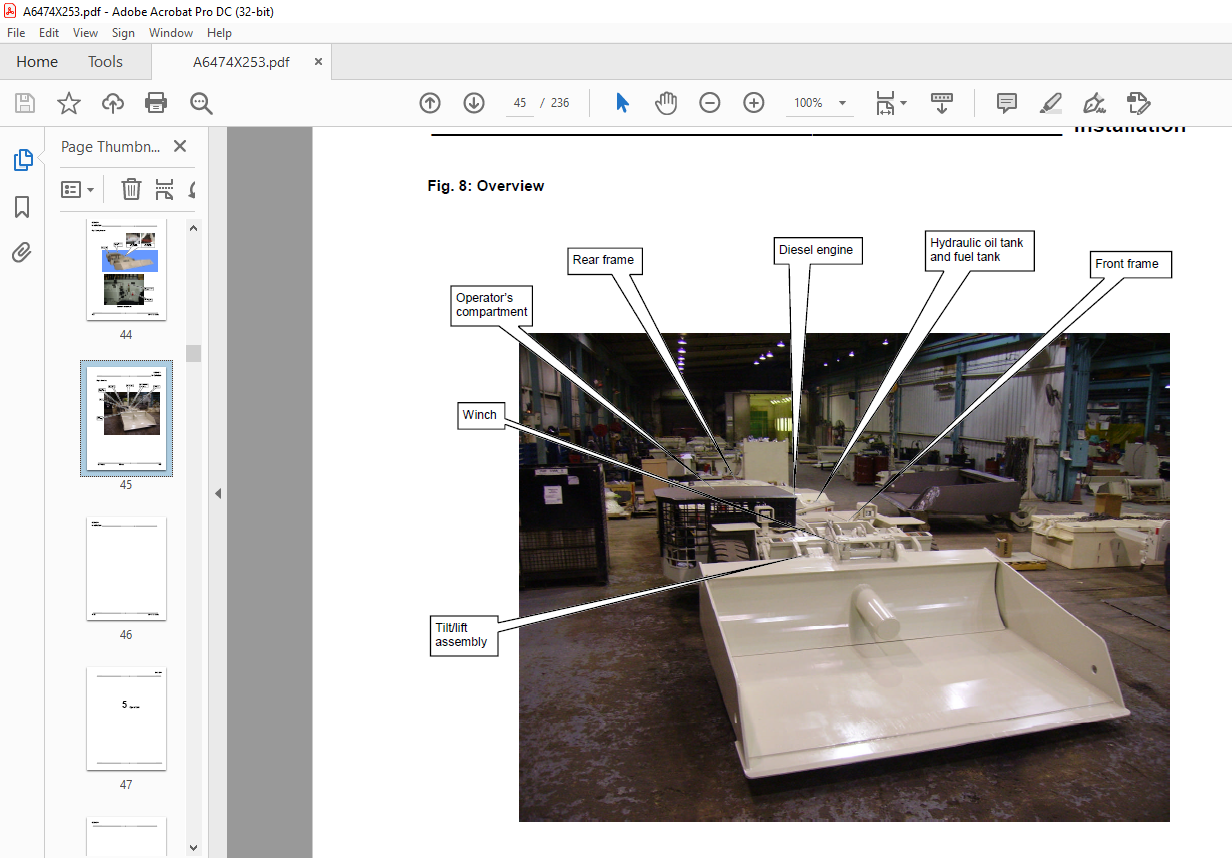
Components of the 488 Diesel Scoop 6.3
Technical data 6.3
Tightening torques 6.11
Permissible data 6.17
Lubrication fluids and greases 6.17
7. For your information
For your information 7.3
Our service 7.3
Service address 7.3
Rebuild facility address 7.4
VIDEO PREVIEW OF THE MANUAL:
S.S


