

CAT Shield support Shield Support 2100 4500-2×7156-2050 2400 4500-2×7156-2050 Operating Manual – PDF DOWNLOAD
FILE DETAILS:
CAT Shield support Shield Support 2100 4500-2×7156-2050 2400 4500-2×7156-2050 Operating Manual – PDF DOWNLOAD
Language : English
Pages :228
Downloadable : Yes
File Type : PDF
DESCRIPTION:
CAT Shield support Shield Support 2100 4500-2×7156-2050 2400 4500-2×7156-2050 Operating Manual – PDF DOWNLOAD
About this manual
This chapter contains important information making it easier for
you to use this manual. It provides you with information on
the structure of the Operating Manual and the symbols used.
operating manual
at hand can result in a safety hazard for yourself and others. Make
sure the information on the shield complies with that given in the
operating manual.
Shield support 2100/4500-2×7156-2050 *
ID no.: 7420 242 000 00 01 face shield
Shield support 2400/4500-2×7156-2050
ID no.: 7420 243 000 00 01 transition shield
Shield support 2400/4500-2×7156-2050
ID no.: 7420 243 000 00 02 transition shield
The operating manual must be accessible at all times to all persons
working on or with the shield.
There should, if possible, always be an operating manual for the
shield available at the place of operation
Persons for whom the operating manual is intended
This operating manual is intended for those persons who work with
or on the shields.
All persons working on the face, at the edge of the face or at the
entry must read this operating manual.
This includes persons who:
- are in charge of transport;
- set up on the installation face;
- perform installation/removal work;
- operate the shields;
- rectify malfunctions;
- perform daily routine work on the face;
- monitor/look after the hydraulic system;
- carry out maintenance work;
- carry out repair work
IMAGES PREVIEW OF THE MANUAL:
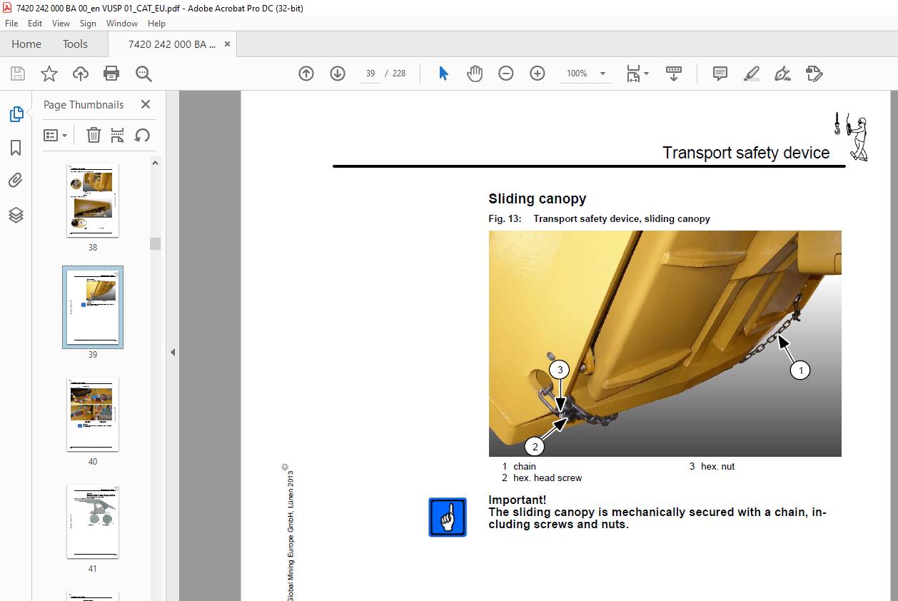
TABLE OF CONTENTS:
CAT Shield support Shield Support 2100 4500-2×7156-2050 2400 4500-2×7156-2050 Operating Manual – PDF DOWNLOAD
1 About this manual
Before starting work 1 3
Persons for whom the operating manual is intended 1 4
Purpose of this operating manual 1 5
Signs and symbols used 1 5
2 Your safety
Personnel 2 3
Operation 2 3
Installation and repairs 2 4
Operating conditions 2 5
Intended use 2 5
Unauthorized use 2 5
Safety instructions 2 6
3 Storage and transport
Storage 3 3
Storing the equipment 3 3
Storing used equipment 3 4
Transport 3 5
Load units, dimensions and weights 3 5
Before transport 3 5
Transport safety device 3 9
Relay bar assembly 3 9
Flipper 3 10
Sliding canopy 3 11
Staple clip 3 12
Side seal 3 13
Transport position 3 14
4 Installation
Preassembly of the shield units 4 3
Installation of the shield units 4 3
Pressure equalization of the electronic control system 4 5
Supply connections for auxiliary supply 4 6
Establishing a connection between the shields 4 9
Requirements for the face hydraulic system 4 10
Water spraying system requirements 4 11
Caterpillar Global
Commissioning 4 12
To be observed prior to commissioning 4 12
How to put the support into operation 4 14
Anticorrosion protection of hydraulic components 4 14
5 Operation
Requirements 5 3
Operating conditions 5 3
Safety requirements 5 6
Operation of the shield support 5 9
Work safety 5 15
Shield components 5 16
Main components 5 16
Overview of shield hydraulics 5 19
HP ball valve versions 5 19
Functions of the HP ball valves 5 21
Operation of the shield hydraulics 5 22
Arrangement of the hydraulic components on
the face shield 5 22
Shield hydraulics for face shield 5 25
Arrangement of the hydraulic components on
the transition shield 5 37
Shield hydraulics for transition shield 5 40
Control units 5 52
Intershield manifold 5 54
PMC®-R control unit 5 55
Double filter 5 57
Shifting ram 5 58
Stabilizing cylinder 5 59
Flipper 5 60
Flipper cylinder 5 61
Caving flap 5 64
Caving flap cylinder 5 64
Dozer cylinder 5 65
Side seal 5 66
Plug with pressure relief 5 67
Measuring coupling for pressure relief 5 68
Repair and emergency operation 5 69
Operation and functions of the electrohydraulic
control unit 5 71
Shield functions 5 73
Operation of the double backflush filter 5 81
Maintenance 5 82
Special measures 5 82
Daily maintenance 5 83
Weekly maintenance 5 84
Every six months 5 84
Regularly scheduled damage assessment 5 84
Troubleshooting 5 85
Instructions for troubleshooting 5 85
Fault localization 5 85
3/2-way or pilot valve 5 88
Piloted check valves 5 88
Internal bypass inside the leg 5 89
Pressure relief valve defective 5 89
Defective or clogged filter 5 89
6 Technical data
Description 6 3
Main subassemblies 6 5
Main dimensions 6 7
Skid 6 9
Relay bar assembly 6 11
Lemniscatic links 6 13
Canopy 6 16
Flipper 6 20
Leg retainer 6 22
Side seal 6 23
Caving shield 6 32
Caving flap 6 36
Accessories 6 38
Conveyor pulling device 6 38
Extensions 6 41
Brackets 6 42
Guides 6 46
Rubber covering 6 48
Assembly clevis 6 49
Movable relay bar 6 50
Technical data, steel structure 6 51
Hydraulic system 6 53
Shield hydraulics 6 53
Hydraulic leg, two-stage (retainer) 6 55
Hydraulic cylinder 6 57
Setup 6 57
Shifting ram (Z2) 6 60
Stabilizing cylinder (Z3) 6 60
Side seal cylinder (Z4) 6 61
Caving flap cylinder (Z5) 6 61
Dozer cylinder (Z6) 6 62
Flipper cylinder (Z7) 6 62
Shifting ram on conveyor pulling device (Z8) 6 63
Base lifting cylinder (Z9) 6 63
Technical data, hydraulic cylinders 6 64
Pressure relief valves 6 67
Angles of inclination of the canopy 6 69
Hydraulic fluids 6 70
Quality of the process water 6 72
Greases and lubricating pastes 6 74
Tightening torques 6 76
Screws and bolts with ISO metric thread 6 76
7 For your information
Standards and directives 7 3
Applied standards and directives 7 3
Identification of the shield 7 5
Name plate 7 5
Shield number 7 6
Caterpillar Global Mining Europe GmbH, Lünen 2013E
VIDEO PREVIEW OF THE MANUAL:
S.M


