

Case Wheel Loader 721E EU Service Workshop Manual
FILE DETAILS:
Case Wheel Loader 721E EU Service Workshop Manual
Size : 137 MB
Format : PDF
Language : English
Brand: Case
Type of machine: Case Wheel Loader
Type of document: Service Manual_Workshop Manual
Model: Case Wheel Loader 721E-EU
Part No:87551874A
DESCRIPTION:
Case Wheel Loader 721E EU Service Workshop Manual
SAMPLE PAGE OF THE MANUAL:
- General The transmission is equipped with a Transmission ECM (Electronic Control Module). This module controls modulation and shifting that were normally associated with hydraulically modulated transmissions, providing smoother shifts and enhanced clutch life. The Transmission ECM relies on signals from several sensors that are incorporated into the design. These sensors measure the speed of several components, as well as other sensors that measure temperature.
- These solenoids and sensors are further defined in the following paragraphs. In addition, the transmission incorporates a two-piece transmission case for ease of transmission maintenance, helical cut gears that help reduce noise, and all external hoses have been eliminated (all oil passages are internal). Transmission ECM Modulation and shifting are controlled by the Transmission Electronic Control Module (Transmission ECM). This module replaces the oil and springs that are found in hydraulically modulated transmissions.
- The Transmission ECM controls the clutch engagement, providing smoother shifts and enhanced clutch life, whether the transmission is set to the automatic or manual shift mode. The Transmission ECM also informs the Information Center, by the use of diagnostic codes, of any transmission error and the hours of operation that the error occurred.
- Electrical Shift Solenoids Electrical Shift Solenoids control the modulation of the clutches, eliminating the need for a modulation valve, and providing a smooth shift while maintaining constant control over clutch engagement as follows: A. A temperature sensor relays the oil temperature to the Transmission ECM. B. The Transmission ECM times the rate the solenoid energizes and de-energizes. C. As the transmission changes gears, there is reduced hesitation from one gear to the next.
- Transmission ECM Tasks The Transmission ECM performs a variety of tasks in the overall system. The Transmission ECM:
- Determines which clutches to engage in the transmission Protects the engine and transmission turbine from overspeed condi t i o ns dur i ng downloading. Receives speed information from the engine speed sensor, the turbine speed sensor, the intermediate shaft speed sensor and the transmission output shaft speed sensor. These speed sensors are checked to determine if normal sensor operation is present. The data is also used to control modulation during shifting and to determine the appropriate shift patterns.
- Detects system failures and determines the appropriate alternative actions. Provides various diagnostic messages to the Information Center. Provides other information to the information center, which in turn displays engine speed, wheel speed, gear shift selection, and actual gear selection. Provides a method to calibrate the transmission clutch control. H. Establishes clutch modulation pressure during transmission shifts.
VIDEO PREVIEW OF THE MANUAL:

IMAGES PREVIEW OF THE MANUAL:

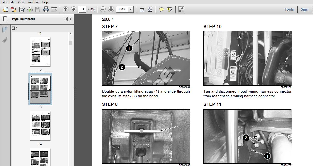
TABLE OF CONTENTS:
Case Wheel Loader 721E EU Service Workshop Manual
General Tab 1
Section Index – General
Standard Torque Specifications 1001
Fluids and Lubricants 1002
Metric Conversion Chart 1003
Engines Tab 2
Section Index – Engines
Engine and Radiator Removal and Installation 2000
Stall Tests 2002
After Cooler 2003
For Engine Repair, See the Engine Service Manual 87600994
Fuel System Tab 3
Section Index – Fuel System
For Fuel System Repair, See the Engine Service Manual 87600994
Electrical Tab 4
Section Index – Electrical
Removal and Installation of Starter and Alternator 4001
Electrical Specifications and Troubleshooting 4002
Batteries 4003
Instrument Cluster 4005
Steering Tab 5
Section Index – Steering
Removal and Installation of Steering Components 5001
Steering Specifications, Pressure Checks, and Troubleshooting 5002
Steering Cylinders 5005
Center Pivot 5006
Auxiliary Steering Motor and Pump 5008
Power Train Tab 6
Section Index – Power Train
Removal and Installation of Power Train Components 6001
Transmission Specifications, Pressure Checks, and Troubleshooting 6002
Transmission 6003
Front Axle 6004
Rear Axle 6004
Drive Shafts, Center Bearing, and Universal Joints 6005
Wheels and Tires 6006
Transmission Control Valve 6007
Brakes Tab 7
Section Index – Brakes
Removal and Installation of Brake Components 7001
Hydraulic Brake Troubleshooting 7002
Brake Pump 7003
Brake Accumulators 7004
Parking Brake 7008
Hydraulics Tab 8
Section Index – Hydraulics
Removal and Installation of Hydraulic Components 8001
Hydraulic Specifications, Troubleshooting, and Pressure Checks 8002
Cleaning the Hydraulic System 8003
Hydraulic Pump 8004
Loader Control Valve 8005
Cylinders 8006
Coupler Solenoid Locking Valve 8007
Ride Control Accumulator 8013
Ride Control Valve 8014
Mounted Equipment Tab 9
Section Index – Mounted Equipment
Air Conditioning Troubleshooting and System Checks For Systems with HFC-134a Refrigerant 9002
Air Conditioner System Service 9003
Removal And Installation Of Air Conditioning And Heater Components 9004
Loader 9006
Roll Over Protective Structure (ROPS), Cab Structural Frame (CSF) 9007
Cab Glass Installation 9010
Electrical Schematic Foldouts and Hydraulic Schematic Foldout In Rear Pocket
PLEASE NOTE:
- This is not a physical manual but a digital manual – meaning no physical copy will be couriered to you. The manual can be yours in the next 2 mins as once you make the payment, you will be directed to the download page IMMEDIATELY.
- This is the same manual used by the dealers inorder to diagnose your vehicle of its faults.
- Require some other service manual or have any queries: please WRITE to us at [email protected]


