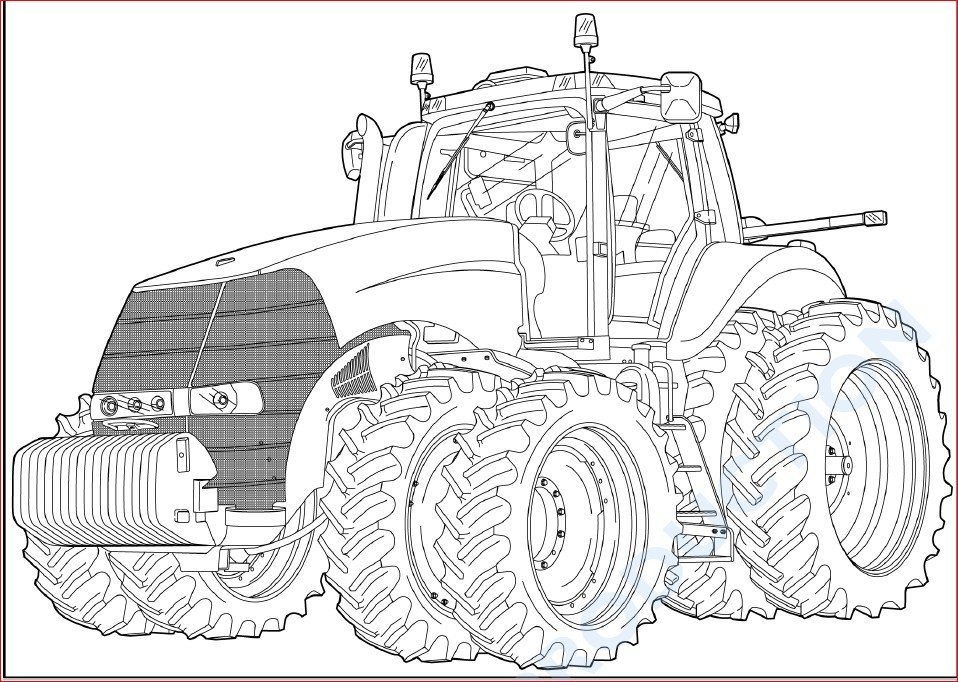
CASE IH MAGNUM 235 260 290 315 340 TRACTOR OPERATORS MANUAL
DESCRIPTION:
This CASE IH MAGNUM 235 260 290 315 340 TRACTOR OPERATORS MANUAL has been developed to assist you in understanding how to operate and maintain your machine. It contains a list of safety precautions, a discussion of the controls and instruments, procedures for operating the machine, a maintenance schedule, a brief troubleshooting section, and a specification section.
The Manual can be viewed on any computer, as well as zoomed and printed. Additional Information: PDF documents may require the newest version of Acrobat Reader to display correctly. Should you have any problems reading your document, please initially try upgrading to the latest version of Adobe Acrobat Reader.
IMAGES:
Table of Contents:
The comprehensive table of contents for the CASE IH MAGNUM 235 260 290 315 340 TRACTOR OPERATORS MANUAL is as follows:
1 GENERAL INFORMATION
Tractor intended use 1-1
Engine tampering 1-1
Emissions warranty 1-2
Electro-Magnetic Compatibility (EMC) 1-4
Manual scope 1-5
Note to the Owner 1-6
Manual storage 1-7
Product identification 1-8
Machine orientation 1-10
Component location 1-11
2 SAFETY INFORMATION
Safety rules and signal word definitions 2-1
Proposition 65 2-2
Safety rules – General 2-2
Safety rules – Air conditioning system 2-3
Safety rules – Basic operating 2-3
Safety rules – Battery 2-4
Safety rules – Driving on public roads 2-4
Safety rules – Electrical storm safety 2-4
Safety rules – Fire prevention 2-5
Safety rules – Front end loader 2-5
Safety rules – General maintenance 2-5
Safety rules – Hazardous chemicals 2-7
Safety rules – Implements, tools and trailers 2-7
Safety rules – Instructional seat 2-7
Safety rules – Mounting and dismounting 2-8
Safety rules – Operator presence system 2-8
Safety rules – Power Take-Off (PTO) operation 2-8
Safety rules – Roll over and tip over 2-9
Safety rules – Utility power lines 2-9
Safety rules – Vehicle vibration 2-10
Safety rules – Wheels and tires 2-10
Roll Over Protective Structure (ROPS) 2-11
Cab protection 2-12
Vehicle vibration levels 2-13
Safety signs 2-14
Selective Catalytic Reduction (SCR) decal 2-24
Ecology and the environment 2-25
3 CONTROLS/INSTRUMENTS
ACCESS TO OPERATOR’S PLATFORM
Tractor access 3-1
Lower step 3-1
NOT FOR REPRODUCTION
OPERATOR’S SEAT
Overview 3-2
Control identification 3-3
INSTRUCTOR’S SEAT
Overview 3-6
FORWARD CONTROLS
Steering column 3-7
Pedal controls 3-10
LEFT-HAND SIDE CONTROLS
Pneumatic trailer brake 3-12
RIGHT-HAND SIDE CONTROLS
Armrest console 3-13
Multi function handle 3-14
Control panel 3-18
Remote valve controls 3-27
Joystick 3-28
Armrest compartment 3-30
Adjusting the armrest console 3-32
REARWARD CONTROLS
Fender console 3-33
Automatic temperature controls 3-36
Automatic temperature control system 3-39
Ventilation 3-40
OVERHEAD CONTROLS
Interior lamps 3-42
EXTERIOR CONTROLS
Rear fender controls 3-43
Front hitch 3-45
INSTRUMENT CLUSTER
Overview 3-46
Gauges 3-47
Status and warning icons 3-48
Upper display 3-51
Lower display 3-53
Keypad 3-55
Setup menu 3-57
Rear tire radius chart 3-63
Adjust menu 3-64
NOT FOR REPRODUCTION
Performance instrumentation 3-71
4 OPERATING INSTRUCTIONS COMMISSIONING THE UNIT
Before starting the engine 4-1
STARTING THE UNIT
Normal engine starting 4-4
Cold starting aids 4-7
Cold temperature operation 4-9
STOPPING THE UNIT
Stopping the engine 4-11
MOVING THE UNIT
Powershift transmission 4-12
Best practices for prolonged transmission life 4-13
Inching pedal and throttle 4-14
Transmission controls 4-15
Upper display 4-18
Driving the vehicle 4-20
Setting default gears 4-25
Automatic Productivity Management (APM) 4-27
Selective Catalytic Reduction (SCR) system 4-34
Selective Catalytic Reduction (SCR) inducement strategy – 2012 4-35
Mechanical Front Drive (MFD) 4-38
Differential lock system 4-42
Suspended axle 4-45
Ride control 4-53
Constant engine speed 4-55
5 TRANSPORT OPERATIONS
ROAD TRANSPORT
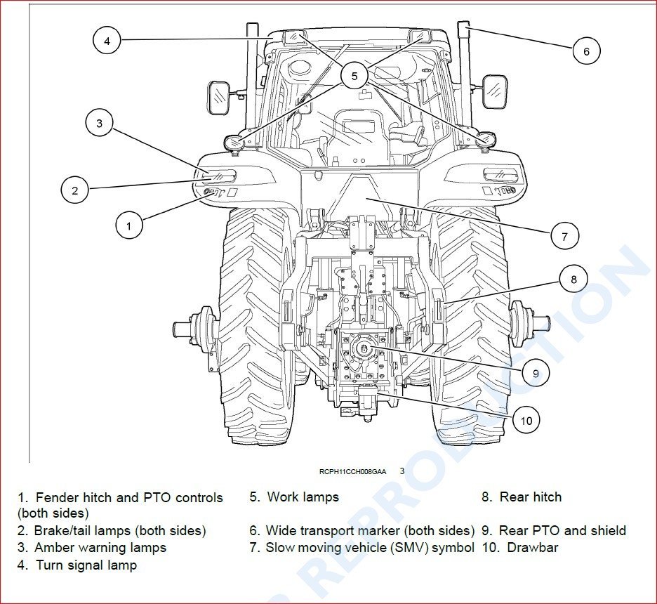
Tractor warning lamps and Slow Moving Vehicle (SMV) symbol 5-1
Wide transport marker light 5-2
Wide transport marker light 5-4
Tractor warning lamps 5-6
Tractor warning lamps 5-7
Safe transport speed 5-8
Implement warning lamps and Slow Moving Vehicle (SMV) symbol 5-9
Safety chain 5-10
SHIPPING TRANSPORT
Securing the tractor for shipping 5-11
NOT FOR REPRODUCTION
RECOVERY TRANSPORT
Safety rules 5-12
Towing the tractor 5-13
6 WORKING OPERATIONS
GENERAL INFORMATION
Overview 6-1
REAR POWER TAKE-OFF (PTO)
Safety rules 6-2
Safety rules 6-5
Connecting the PTO 6-8
Connecting the Power Take-Off (PTO) 6-9
Interchangeable Power Take-Off (PTO) shaft 6-10
Rear Power Take-Off (PTO) operation 6-16
Power Take-Off (PTO) fender switch operation 6-20
Auto Power Take-Off (PTO) operation 6-21
FRONT POWER TAKE-OFF (PTO)
Overview 6-24
Front Power Take-Off (PTO) operation 6-25
REAR HITCH
Identification 6-28
Link adjustment 6-29
Hitch high clearance adjustment 6-33
Hydraulic links 6-36
Sway limiter adjustment 6-38
Lower link block adjustment 6-39
Mechanical float adjustment 6-40
Hitch quick coupler – Category III/IIIN 6-41
Hitch quick coupler – Category IVN 6-46
Hitch operation 6-50
Hitch remote switch operation 6-55
Load control operation 6-56
Hitch set point 6-58
FRONT HITCH
Overview 6-60
Front hitch operation 6-61
DRAWBARS AND TOWING ATTACHMENTS
Drawbars and towing hitches – Safety rules 6-68
NOT FOR REPRODUCTION
Drawbar capacity/position 6-69
Adjusting the drawbar 6-73
AUXILIARY POWER CONNECTIONS
Auxiliary power and lighting 6-75
Cab power connections 6-77
HYDRAULIC REMOTE CONTROL VALVES
Valve couplers and connections 6-79
Motor return circuit 6-82
Power beyond circuit 6-83
Flow capacity 6-84
Hydraulic transport lock 6-85
Operating the controls 6-86
Remote valve display screens 6-90
Remote hydraulic auto mode 6-94
Auto depth control 6-96
Joystick operation 6-98
BALLASTING THE TRACTOR
Guidelines 6-103
Tire load and inflation charts 6-108
Weights, cast metal and liquid 6-120
Wheel slip and power hop performance 6-129
MECHANICAL FRONT DRIVE (MFD) AXLES
Tire combinations and tread positions 6-132
Steering and oscillation stops 6-139
Tread and fender settings – standard axles 6-142
Tread and fender settings – heavy duty axles 6-146
Tread and fender settings – heavy duty class 5 axles 6-153
Tread and fender settings – heavy duty class 5 suspended axles 6-161
Tread and fender settings – scissors suspended axles 6-173
REAR AXLE
Rear wheel installation 6-185
Rear wheel tread settings 6-188
7 MAINTENANCE
GENERAL INFORMATION
Safety rules 7-1
Opening the hood 7-3
Closing the hood 7-4
Filling the fuel tank 7-5
Filling the Diesel Exhaust Fluid (DEF)/AdBlue® tank 7-6
NOT FOR REPRODUCTION
Battery access and service 7-7
Tire and rim service 7-9
Tractor jacking points 7-11
Capacities 7-13
Consumables – Engine oil 7-15
Consumables – Diesel fuel 7-17
Consumables – Biodiesel fuels 7-18
Consumables – Diesel exhaust fluid (DEF)/AdBlue® 7-20
Consumables – Coolant solutions 7-22
Electrical component location 7-23
Lamps and bulbs 7-28
Maintenance chart notes 7-29
MAINTENANCE CHART
Maintenance Chart 7-30
At warning message display
Air filter service icon/message 7-32
Fuel filter water separator 7-33
Transmission oil filter switch 7-34
Hydraulic oil filter switch 7-36
First 10 to 50 hours
Differential and planetary oil 7-38
Wheel bolt torque 7-38
Weight bolt torque 7-38
Every 10 hours or daily
Engine oil level 7-39
Transmission oil level 7-40
Engine coolant level 7-40
Engine auxiliary fuel filter 7-41
Air reservoir 7-41
Rear hitch and front axle 7-41
Every 50 hours or weekly
Engine fuel pre-filter 7-42
Every 100 hours
Front hitch 7-43
Front Power Take-Off (PTO) drive shaft 7-45
Every 300 hours
Battery water level (Note E) 7-46
Engine air intake hoses 7-48
Engine coolant level – deaeration tank 7-50
NOT FOR REPRODUCTION
Wheel bolt torque 7-51
Weight bolt torque 7-51
Front axle (Note A) 7-52
Rear hitch (Note A) 7-60
Fuel tank 7-62
Differential and planetary oil level (Note B) 7-63
Transmission oil pressure 7-65
Front Power Take-Off (PTO) oil level 7-66
Every 400 hours
Cab air filter 7-67
Every 600 hours
Engine oil and filter 7-70
Engine coolant antifreeze protection 7-72
Engine coolant hoses and clamps 7-72
Engine primary fuel filter 7-74
Engine fuel pre-filter 7-77
Fuel system bleeding 7-80
Changeable Power Take-Off (PTO) internal splines 7-82
Diesel Exhaust Fluid (DEF)/AdBlue® in-line filter 7-83
Front Power Take-Off (PTO) oil and filter 7-85
Every 1000 hours or annually
Pneumatic brake system dryer 7-87
Every 1200 hours or annually
Differential and planetary oil 7-88
Engine air filters 7-93
Engine air precleaner 7-97
Every 1500 hours
Transmission oil 7-99
Transmission oil filter 7-101
Regulated transmission filter 7-102
Engine crankcase filter 7-103
Every 2000 hours
Engine coolant 7-107
Every 3000 hours
Emergency steering system 7-110
Engine valve adjustment (Note C) 7-110
NOT FOR REPRODUCTION
Every 3600 hours
Diesel Exhaust Fluid (DEF)/AdBlue® supply module filter 7-111
As required
Vehicle fire prevention 7-111
Engine primary air filter 7-112
Grille screen and radiator area 7-115
Fuel tank vent filter 7-117
Transmission clutch and accumulator 7-117
Tire pressure 7-117
Fan belt 7-118
Cab suspension, if equipped 7-122
Remote valve collection bottle 7-123
Engine auxiliary fuel filter 7-124
Cab fabric and carpet 7-126
Seat belt 7-126
STORAGE
Tractor storage 7-127
Removal from storage 7-128
ELECTRICAL SYSTEM
Radio or audio system 7-129
Battery removal and installation 7-130
Auxiliary battery connections 7-132
Headlight 7-133
Flood and work light 7-136
Fender tail light and warning light 7-138
Roof front warning and work light 7-140
Rear roof warning light 7-143
High intensity work light 7-145
Wide transport marker light 7-147
Rotating beacon light 7-148
Interior light 7-149
8 TROUBLESHOOTING
ALARM(S)
Display warnings overview 8-1
Display warnings – Level 1 8-2
Display warnings – Level 2 8-5
Display warnings – Level 3 8-8
Display warnings – Level 4 8-10
SYMPTOM(S)
Engine symptoms 8-12
NOT FOR REPRODUCTION
Transmission symptoms 8-14
Hydraulic symptoms 8-15
Hitch symptoms 8-16
Brake symptoms 8-17
Cab environment symptoms 8-18
Electrical power system symptoms 8-19
9 SPECIFICATIONS
Engine specifications 9-1
Power train specifications 9-2
Operating speeds 9-5
Vehicle dimensions and shipping weight 9-12
Maximum operating weight 9-15
10 ACCESSORIES
Front wheel fenders 10-1
Farming system displays 10-7
Chemical tank mounting 10-8
Loader connection and operation 10-10
Trailer brake connections 10-11
General accessories 10-13
GENERAL INFORMATION
Tractor intended use Magnum series tractors with standard equipment and authorized attachments, are intended to be used for customary farming, land leveling and related agriculture operations (intended use). Installation of utility (dozer) blades, tile plows, or push bars on the tractor is not recommended. Any tractor damage resulting from the installation and/or use of such equipment is not covered by the tractor warranty. Consult an authorized dealer changes, additions or modifications that can be required for this machine to comply with various regulations and safety requirements. Unauthorized modifications will cause serious injury or death. Anyone making such unauthorized modifications is responsible for the consequences. The tractor is not designed for light/heavy forestry applications; usage is prohibited for forestry applications. Do not use this machine for any purpose or in any manner other than as described in the manual, decals, or other product safety information provided with the machine. These materials define the machine’s intended use. Use in any other way is considered as contrary to the intended use. The manufacture accepts no liability for any damage or injury resulting from this misuse and these risks must be born solely by the user.


Reviews
There are no reviews yet.