

Bobcat 773 Loader Service Manual 6900092 (6-12) – PDF DOWNLOAD
FILE DETAILS:
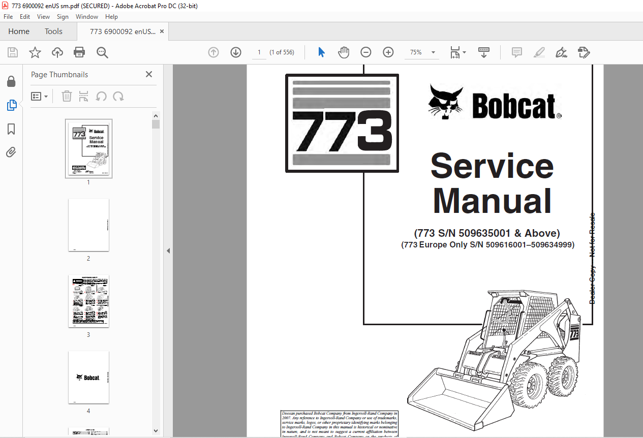
Bobcat 773 Loader Service Manual 6900092 (6-12) – PDF DOWNLOAD
Language : English
Pages : 556
Downloadable : Yes
File Type : PDF
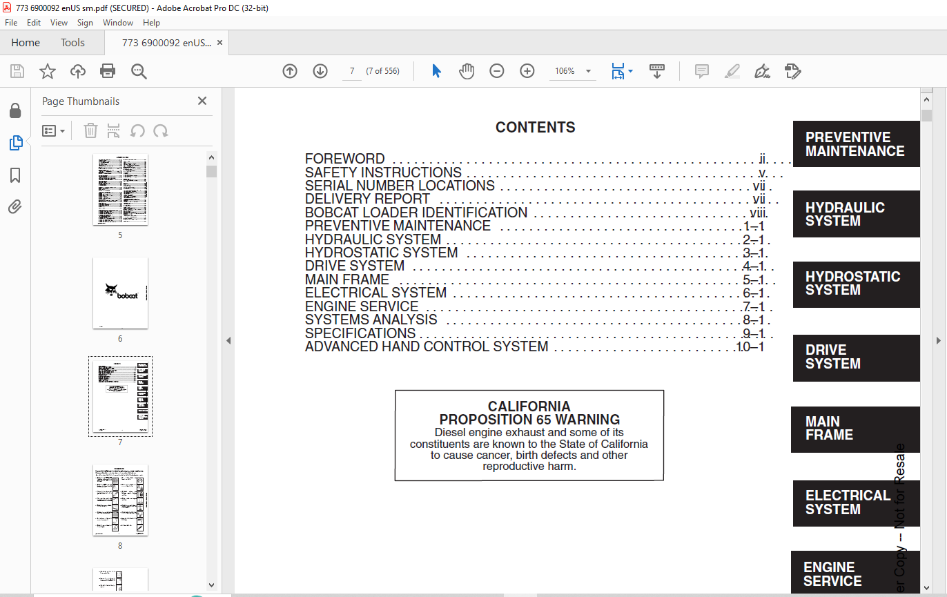
TABLE OF CONTENTS:
Bobcat 773 Loader Service Manual 6900092 (6-12) – PDF DOWNLOAD
MAINTENANCE SAFETY 3
ALPHABETICAL INDEX 5
CONTENTS 7
FOREWORD 8
SAFETY INSTRUCTIONS 11
FIRE PREVENTION 12
SERIAL NUMBER LOCATIONS 13
LOADER SERIAL NUMBER 13
ENGINE SERIAL NUMBER 13
DELIVERY REPORT 13
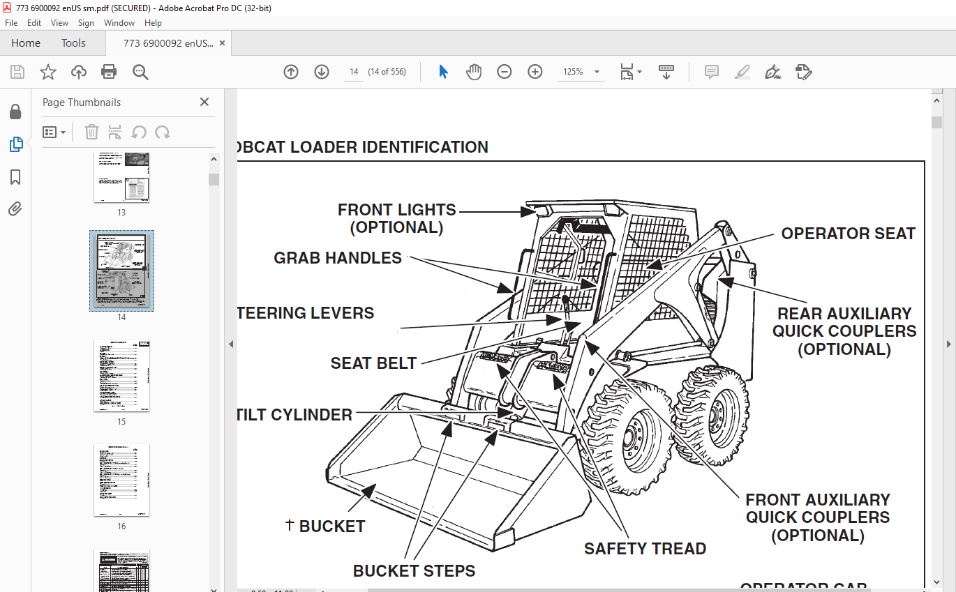
BOBCAT LOADER IDENTIFICATION 14
PREVENTIVE MAINTENANCE 15
SERVICE SCHEDULE 17
LIFTING AND BLOCKING THE LOADER 18
Procedure 18
TRANSPORTING THE BOBCAT LOADER 19
TOWING THE LOADER 19
LIFTING THE LOADER 20
Single Point Lift 20
STOPPING THE BOBCAT LOADER 20
LIFT ARM SUPPORT DEVICE 21
Installing Lift Arm Support Device 21
Removing Lift Arm Support Device 21
OPERATOR CAB 22
Description 22
Emergency Exit 22
Raising The Operator Cab 23
Lowering The Operator Cab 24
SEAT BAR RESTRAINT SYSTEM (Foot Pedals) 25
Description 25
Seat Bar Inspection 25
Seat Bar Maintenance 25
SEAT BAR RESTRAINT SYSTEM (Mechanical Hand Controls) 26
Description 26
Seat Bar Inspection 26
Seat Bar Maintenance 26
SEAT BAR RESTRAINT SYSTEM (Advanced Hand Controls) 27
Description 27
Seat Bar Inspection 27
Seat Bar Maintenance 27
AIR CLEANER SERVICE 28
Replacing Filter Element 28
FUEL SYSTEM 30
Fuel Specifications 30
Filling The Fuel Tank 30
Fuel Filter 30
Removing Air From The Fuel System 31
ENGINE LUBRICATION SYSTEM 32
Checking Engine Oil 32
Replacing Oil And Filter 32
ENGINE COOLING SYSTEM 34
Cleaning The Cooling System 34
Checking The Coolant Level 34
Replacing The Coolant 35
ALTERNATOR BELT 36
Adjustment 36
FAN GEARBOX 36
Checking And Maintaining 36
HYDRAULIC/HYDROSTATIC SYSTEM 37
Checking And Adding Fluid 37
Replacing Hydraulic/Hydrostatic Filter 37
Replacing Hydraulic Fluid 38
Breather Cap 39
SPARK ARRESTOR MUFFLER 40
Cleaning Procedure 40
TIRE MAINTENANCE 41
Wheel Nuts 41
Tire Rotation 41
Tire Mounting 41
FINAL DRIVE TRANSMISSION (CHAINCASE) 42
Checking And Adding Oil 42
Removing Oil From The Chaincase 42
DRIVE BELT 43
Adjusting The Drive Belt Equipped With The Fixed Drive Idler 43
Adjusting The Drive Belt Equipped With The Spring Loaded Drive Idler 45
Drive Belt Replacement 46
LUBRICATION OF THE BOBCAT LOADER 47
PIVOT PINS 49
BOB–TACH 50
Inspection And Maintenance 50
REMOTE START SWITCH 51
Procedure 51
HYDRAULIC SYSTEM 53
HYDRAULIC / HYDROSTATIC SCHEMATICS 57
TROUBLESHOOTING 69
HYDRAULIC SYSTEM INFORMATION 70
Tightening Procedures 70
LIFT CYLINDERS 71
Checking The Lift Cylinder(s) For Internal Leakage 71
Removal And Installation 71
TILT CYLINDERS 72
Checking The Tilt Cylinder For Internal Leakage 72
Removal And Installation 72
Rod End Seal Replacement 73
HYDRAULIC CYLINDER IDENTIFICATION 74
Lift Cylinder Components 74
Tilt Cylinder Components 75
HYDRAULIC CYLINDERS 76
Disassembly 76
Assembly 78
BICS™ VALVE (S/N 509640660 & Above, S/N 509616542 & Above) 84
Removal 84
Lift Arm By–Pass Orifice Disassembly 85
Check Valve Disassembly 85
Lock Valve Disassembly 86
BICS™ Valve Solenoid Disassembly 87
BICS™ Valve Solenoid Assembly 88
Lock Valve Assembly 89
Check Valve Assembly 89
Lift Arm By–Pass Orifice Assembly 90
Installation 91
CONTROL VALVE (S/N 509640660 & Above, S/N 509616542 & Above) 92
Removal And Installation 92
Identification Chart 95
Disassembly 96
Lift Base End Restrictor Disassembly 96
Load Check Valve Disassembly 96
Main Relief Valve Disassembly 97
Port Relief Valve Disassembly 98
Anti–Cavitation Valve Disassembly 99
Rubber Boot Disassembly 100
Lift Spool And Detent Disassembly 101
Tilt Spool And Centering Spring Disassembly 104
Auxiliary Spool Disassembly 106
Auxiliary Electric Solenoid Disassembly 107
Port–Auxiliary Section Disassembly 108
Cleaning And Inspection 108
Port–Auxiliary Section Assembly 109
Auxiliary Electric Solenoid Assembly 109
Auxiliary Spool Assembly 110
Tilt Spool And Centering Spring Assembly 111
Lift Spool And Detent Assembly 113
Rubber Boot Assembly 115
Anti–Cavitation Valve Assembly 116
Port Relief Valve Assembly 117
Main Relief Valve Assembly 118
Load Check Valve Assembly 118
Spool Seal Installation 120
CONTROL VALVE (S/N 509640659 & Below, S/N 509616541 & Below) 121
Removal And Installation 121
Identification Chart 124
Disassembly And Assembly 125
Load Check Valve 125
Main Relief Valve 126
Port Relief Valve 126
Anti–Cavitation Valve 127
Rubber Boot 128
Lift Spool Detent 129
Tilt Centering Spring 133
Auxiliary Spool 134
Auxiliary Electric Solenoid 135
Inspection 136
Identification And Installation Of Spool Seal 137
MAIN RELIEF VALVE 138
Checking 138
Adjustment 139
Removal and Installation 139
HYDRAULIC PUMP 140
Removal And Installation 140
Checking The Output Of The Hydraulic Pump 142
Disassembly And Assembly 144
Inspection 146
Identification 146
HYDRAULIC FILTER HOUSING 147
Removal And Installation 147
HYDRAULIC FLUID RESERVOIR 148
Removal And Installation 148
CONTROL PEDALS 149
Removal And Installation 149
Pedal Adjustment 149
CONTROL INTERLOCK LINKAGE (Pedal or Mechanical Hand) 150
Removal And Installation 150
Adjustment 151
LIFT LOCK BY–PASS VALVE 152
Removal And Installation (S/N 509640660 & Above S/N 509616542 & Above) 152
Disassembly And Assembly (S/N 509640660 & Above S/N 509616542 & Above) 153
Removal And Installation (S/N 509640659 & Below, S/N 509616541 & Below) 154
Disassembly And Assembly (S/N 509640659 & Below, S/N 509616541 & Below) 155
TILT LOCK VALVE 156
Removal And Installation (S/N 509640659 & Below, S/N 509616541 & Below) 156
Disassembly And Assembly (S/N 509640659 & Below, S/N 509616541 & Below) 158
HYDROSTATIC SYSTEM 159
TROUBLESHOOTING 161
HYDROSTATIC SYSTEM INFORMATION 162
Replenishing Valve Function 162
Checking Charge Pressure 162
CONTROL PANEL 163
Removal and Installation 163
Steering Shock Removal And Installation 164
Steering Shaft Removal And Installation 164
Steering Shaft Disassembly And Assembly 164
Steering Lever Removal And Installation 165
Rubber Boot Replacement 165
STEERING LINKAGE 166
Removal And Installation 166
Steering Linkage Adjustment 168
Steering Neutral Adjustment 170
HYDROSTATIC DRIVE MOTOR 172
Removal And Installation 172
Parts Identification – (S/N 509639898 & Below & S/N 509616504 & Below) 173
Disassembly And Assembly (S/N 509639898 & Below & S/N 509616504 & Below) 174
Inspection (S/N 509639898 & Below & S/N 509616504 & Below) 179
Timing the Hydrostatic Motor (S/N 509639898 & Below & S/N 509616504 & Below) 180
Parts Identification – (S/N 509639899 & Above & S/N 509616505 & Above) 181
Disassembly (S/N 509639899 & Above & S/N 509616505 & Above) 182
Assembly (S/N 509639899 & Above & S/N 509616505 & Above) 187
HYDROSTATIC PUMP 193
Removal And Installation 193
Identification 196
Disassembly And Assembly 198
Inspection 206
Swashplate Pre–Load 208
DRIVE BELT HOUSING 209
Removal And Installation 209
SPRING LOADED DRIVE BELT TENSIONER PULLEY 211
Removal And Installation 211
Identification 212
Disassembly 213
Assembly 214
FIXED DRIVE BELT TENSIONER PULLEY 216
Removal And Installation 216
Identification 217
Disassembly 218
Assembly 220
Checking Pulley End Play 224
OIL COOLER 224
Removal and Installation 224
DRIVE SYSTEM 225
PARKING BRAKE 227
Removal And Installation 227
Disassembly And Assembly 227
PARKING BRAKE DISC 228
Removal And Installation 228
TRACTION LOCK GUIDES 229
Disassembly 229
Assembly 230
CHAINCASE FLUID 232
Removing Oil From The Chaincase 232
CHAINCASE COVERS 233
Center Chaincase Cover Removal And Installation 233
Front Chaincase Cover Removal And Installation 234
Rear Chaincase Cover Removal And Installation 234
MOTOR CARRIER 235
Shaft Seal Replacement 235
Removal And Installation 237
Disassembly 238
Assembly 239
AXLE SEAL 243
Removal And Installation 243
AXLE, SPROCKET AND BEARINGS 245
Removal And Installation 245
DRIVE CHAIN 249
Removal And Installation 249
MAIN FRAME 251
SEAT BAR (W/GAS CYLINDER) 253
Removal And Installation 253
Assembly 255
Compressing The Gas Cylinder 256
SEAT BAR (W/COMPRESSION SPRINGS) 257
Removal And Installation 257
Assembling Components 260
Compression Spring Disassembly And Assembly 260
OPERATOR CAB GAS CYLINDER 261
Removal And Installation 261
Disassembly And Assembly 262
OPERATOR CAB 263
Removal And Installation 263
OPERATOR SEAT 265
Removal And Installation 265
BOB–TACH 266
Removal And Installation 266
Bob–Tach Lever And Wedge 268
Bob–Tach Stops 269
LIFT ARMS 270
Removal And Installation 270
LIFT ARM LINK 272
Removal And Installation 272
REAR GRILL 274
Removal And Installation 274
FUEL TANK 275
Removal And Installation 275
Fuel Level Sender 276
REAR DOOR 277
Removal And Installation (Two Piece Door) 277
Removal And Installation (One Piece Door) 278
Hood Removal And Installation (Two Piece Door) 279
Bumper Removal And Installation (Two Piece Door) 279
Door Latch Removal And Installation 279
Door Latch And Catch Adjustment 280
REAR LIGHTS 281
Rear Lights Removal and Installation (One Piece Door) 281
ELECTRICAL SYSTEM 283
ELECTRICAL SCHEMATICS 285
TROUBLESHOOTING 319
ELECTRICAL SYSTEM INFORMATION 320
Description 320
Fuse Location 320
BATTERY 321
Removal And Installation 321
Servicing The Battery 322
Using A Booster Battery (Jump Starting) 323
ALTERNATOR 324
Alternator Output Test 324
Rectifier (Diode) Test 324
Alternator Regulator Test 325
Removal And Installation 326
Adjusting The Alternator Belt 326
Disassembly And Inspection 327
Stator Continuity Test 327
Stator Ground Test 327
Rotor Continuity Test 328
Rotor Ground Test 328
Rectifier Continuity (Diode) Test 328
Assembly 329
STARTER 330
Removal And Installation 330
STARTER (DELCO REMY) 330
Checking the Starter 330
Parts Identification 331
Disassembly and Assembly 332
Cleaning and Inspection 334
STARTER (DENSO) 335
Parts Identification 335
Disassembly 336
Inspection And Repair 341
No Load Test 344
Assembly 344
STANDARD INSTRUMENT PANEL 351
Removal And Installation 351
FRONT LIGHTS 352
Removal And Installation 352
RELAY SWITCHES 353
Location 353
ENGINE SERVICE 355
TROUBLESHOOTING 357
ENGINE SPEED CONTROL 358
Removal And Installation 358
Disassembly 358
ENGINE MUFFLER 359
Removal And Installation 359
RADIATOR 360
Removal And Installation 360
BLOWER HOUSING/FAN GEARBOX 362
Removal And Installation 362
Tension Pulley Removal And Installation 365
Blower Fan Disassembly And Assembly 366
FAN GEARBOX 368
Identification 368
Disassembly 369
Assembly 374
Checking Backlash 379
AIR CLEANER 382
Removal And Installation 382
ENGINE 383
Removal And Installation 383
Engine Mount Replacement 388
FLYWHEEL 389
Removal And Installation 389
Flywheel Ring Gear 389
ENGINE COMPRESSION 390
Checking 390
GLOW PLUGS 391
Checking The Glow Plugs 391
Removal And Installation 392
FUEL INJECTION PUMP 393
Checking The Injection Pump 393
Adjusting Shut–Off Linkage 393
Removal And Installation 394
Timing The Injection Pump 397
FUEL INJECTION NOZZLES 398
Removal And Installation 398
Checking The Injector Nozzle 400
CYLINDER HEAD 401
Removal And Installation 401
Disassembly And Assembly 402
Servicing The Cylinder Head 403
Top Clearance 403
VALVE, VALVE SEAT AND GUIDE 404
Checking The Valve Guide 404
Reconditioning The Valve And Valve Seat 405
Valve Spring 406
VALVE CLEARANCE 407
Adjustment 407
ROCKER ARM AND SHAFT 407
Checking 407
TIMING GEARCASE COVER 408
Removal And Installation 408
IDLER GEAR AND CAMSHAFT 410
Removal And Installation 410
Servicing The Camshaft 411
Servicing The Idler Gear And Shaft 412
TIMING GEARS 413
Checking Backlash 413
FUEL CAMSHAFT 414
Removal And Installation 414
Governor 414
CRANKSHAFT GEAR 415
Removal And Installation 415
OIL PUMP 415
Removal And Installation 415
Oil Pump Service 415
Checking Engine Oil Pressure 416
Relief Valve 416
PISTON AND CONNECTING ROD 417
Removal And Installation 417
Servicing The Piston And Connecting Rod 418
Connecting Rod Alignment 420
CRANKSHAFT AND BEARINGS 421
Removal And Installation 421
Servicing The Crankshaft And Bearings 422
CYLINDER BORE 426
Checking The Cylinder Bore 426
WATER PUMP 427
Disassembly And Assembly 427
SYSTEMS ANALYSIS 429
BOBCAT INTERLOCK CONTROL SYSTEM (BICS™) (S/N 509648900 & Above) (S/N 509617300 & Above) 431
Inspecting The BICS™ Controller 431
nspecting Deactivation Of The Auxiliary Hydraulics System 431
Inspecting The Seat Bar Sensor (Engine RUNNING) 431
Inspecting The Traction Lock (Engine RUNNING) 431
Inspecting The Lift Arm By–Pass Control 431
Additional Inspection For Loaders With Advanced Hand Controls 431
Troubleshooting Chart 432
BOBCAT INTERLOCK CONTROL SYSTEM (BICS™) (S/N 509648899 & Below) (S/N 509617299 & Below) 433
Inspecting The BICS™ Controller (Engine STOPPED – Key ON) 433
Inspecting Deactivation Of The Auxiliary Hydraulics System (Engine STOPPED – Key ON) 433
Inspecting The Seat And Seat Bar Sensors (Engine Running) 433
nspecting The Traction Lock (Engine Running) 433
nspecting The Lift Arm By–Pass Control 433
Maintenance 434
Troubleshooting Chart 435
BOBCAT INTERLOCK CONTROL SYSTEM (BICS™) 436
Troubleshooting Guide 436
BICS CONTROLLER 436
TRACTION LOCK 437
SEAT SENSOR 438
SEAT BAR SENSOR 439
SEAT SENSOR 440
Seat Sensor Test 440
Removal And Installation 441
BICS™ Controller Seat Sensor Circuit Test 442
BICS™ SYSTEM CONTROLLER 443
Removal And Installation 443
SEAT BAR SENSOR 444
Seat Bar Sensor Test 444
Removal And Installation 445
BICS™ Controller Seat Bar Sensor Circuit Test 446
TRACTION LOCK 447
Removal And Installation 447
BOSS® DIAGNOSTIC TOOL 449
Procedure 449
SENDER AND SENSOR 449
Service Checks 449
RPM SENSOR 449
Adjustment 449
MONITOR SERVICE CODES 450
TROUBLESHOOTING THE BOSS® & LCD DISPLAY 453
OPERATION SENSING SYSTEM UNIT 454
Removal And Installation 454
BOSS® INSTRUMENT PANEL 455
Removal And Installation 455
ELECTRICAL/HYDRAULIC CONTROLS REFERENCE 456
Controls Identification Chart 456
SPECIFICATIONS 457
SKID STEER LOADER SPECIFICATIONS 459
PERFORMANCE 459
CONTROLS 459
ENGINE 459
HYDRAULIC SYSTEM 460
ELECTRICAL 460
DRIVE SYSTEM 460
CAPACITIES 460
TIRES 460
FLOOR PRESSURE 460
ENGINE SPECIFICATIONS 461
Fuel Injection Nozzles 461
Fuel Injection Pump 461
Cylinder Head 461
Valves 461
Valve Springs 461
Valve Timing 461
Rocker Arms 461
Camshaft 462
Tappet 462
Cylinders 462
Piston Rings 462
Pistons 462
Connecting Rod 462
Oil Pump 462
Crankshaft 463
Timing Gear 463
Thermostat 463
Crankshaft Re–Grind Data 464
Torque For General Metric Bolts 465
HYDRAULIC CONNECTION SPECIFICATIONS 466
O–ring Face Seal Connection 466
Straight Thread O–ring Fitting 466
Straight Thread O–ring Fitting 466
Flare Fitting 466
O–ring Flare Fitting 467
Port Seal Fitting 469
HYDRAULIC/HYDROSTATIC FLUID SPECIFICATIONS 470
TORQUE SPECIFICATIONS FOR LOADER 471
STANDARD TORQUE SPECIFICATIONS FOR BOLTS 472
DECIMAL AND MILLIMETER EQUIVALENTS 473
U S TO METRIC CONVERSION 473
ADVANCE HAND CONTROL SYSTEM (AHC) 475
ADVANCED HAND CONTROL ELECTRICAL SCHEMATICS 477
AHC COMPONENTS 487
Identification 487
TROUBLESHOOTING (AHC) 488
ACTUATOR VOLTAGE TEST 490
Procedure 490
HANDLE CONTROL UNIT TEST 493
Procedure 493
BOBCAT INTERLOCK CONTROL SYSTEM (BICS™) 496
ADVANCED HAND CONTROLS (AHC) 496
AHC/PWM CONTROLLER 497
Removal And Installation 497
Test 497
Description 498
Conditions 499
Troubleshooting Chart 499
Handle Testing 500
Solenoid Coil Testing 500
CONTROL HANDLE (ADVANCED HAND CONTROL) (AHC) 501
Control Handle Unit Removal And Installation 501
Control Unit Connector 504
Switch Handle Removal And Installation 505
AHC Handle Removal And Installation 508
AHC Handle Disassembly And Assembly 509
AHC Steering Lever Removal And Installation 510
AHC Steering Lever Boot 510
Actuators Removal And Installation 511
Actuators Disassembly And Assembly 512
CONTROL HANDLE (ADVANCED HAND CONTROL) (AHC) (W/PUSH BUTTON FLOAT) 513
Components Identification 513
Controller Connector And Wire Identification 514
AHC/PWM Controller Removal And Installation 515
Handle Sensor Removal And Installation 516
Handle Sensor Connector 518
Switch Handle Removal And Installation 519
Control Handle Removal And Installation 522
Control Handle Disassembly And Assembly 523
Control Lever Removal And Installation 524
Control Lever Boot 525
Actuators Disassembly And Assembly 526
BICS™ VALVE 527
Lift Arm By–Pass Orifice 527
Check Valve 528
Lock Valve 528
BICS™ Valve Solenoid 529
Removal And Installation 530
HYDRAULIC CONTROL VALVE 531
Removal And Installation 531
Identification Chart 533
Disassembly And Assembly 534
Load Check Valve 534
Lift Base End Restrictor 534
Main Relief Valve 535
Port Relief Valve (Lift) 536
Anti–Cavitation/Port Relief Valve 536
Port Relief Valve (Tilt) 537
Anti–Cavitation Valve 537
Rubber Boot 538
Lift And Tilt Spool 539
Inspection 541
Auxiliary Spool 542
Auxiliary Electrical Solenoid 543
Spool Seal Installation 544
H–Port Auxiliary Section 545
SERVICE MANUAL REVISIONS 547
773–1 547
773–2 549
773–3 551
773–4 553
773-5 555
DESCRIPTION:
Bobcat 773 Loader Service Manual 6900092 (6-12) – PDF DOWNLOAD
(773 S/N 509635001 & Above)
(773 Europe Only S/N 509616001–509634999)
FOREWORD:
This manual is for the Bobcat loader mechanic. It provides necessary servicing and adjustment procedures for the Bobcat loader and its component parts and systems. Refer to the Operation & Maintenance Manual for operating instructions, starting procedure, daily checks, etc.
SAFETY INSTRUCTIONS:
The following publications provide information on the safe use and maintenance of the loader and attachments:
• The Delivery Report is used to assure that complete instructions have been given to the new owner and that the machine
is in safe operating condition.
• The Operation & Maintenance Manual delivered with the loader gives operating information as well as routine maintenance
and service procedures. It is a part of the loader and must stay with the machine when it is sold. Replacement Operation
& Maintenance Manuals can be ordered from your Bobcat loader dealer.
• The loader has machine signs (decals) which instruct on the safe operation and care. The signs and their locations are
shown in the Operation & Maintenance Manual. Replacement signs are available from your Bobcat loader dealer.
• The loader has a plastic Operator’s Handbook fastened to the operator cab. Its brief instructions are convenient to the
operator. The Handbook is available from your dealer in an English edition or one of many other languages. See your Bobcat
dealer for more information on translated versions.
• The EMI Safety Manual (available in Spanish) delivered with the loader gives general safety information.
• The Service Manual and Parts Manual are available from your dealer for use by mechanics to do shop–type service and
repair work.
• The Skid–Steer Loader Operator Training Course is available through your local dealer. This course is intended to provide
rules and practices for correct operation of the Bobcat loader. The course is available in English and Spanish version.
• The Service Safety Training Course is available from your Bobcat dealer. This course provides information for safe and
correct service procedures for Bobcat Skid–Steer loaders.
• The Bobcat Skid–Steer Loader Safety Video is available from your Bobcat Dealer.
VIDEO PREVIEW OF THE MANUAL:
IMAGES PREVIEW OF THE MANUAL:
PLEASE NOTE:
- This is not a physical manual but a digital manual – meaning no physical copy will be couriered to you. The manual can be yours in the next 2 mins as once you make the payment, you will be directed to the download page IMMEDIATELY.
- This is the same manual used by the dealers inorder to diagnose your vehicle of its faults.
- Require some other service manual or have any queries: please WRITE to us at [email protected]
S.V


