

2008 Polaris Sportsman 500 Service Manual
FILE DETAILS:
2008 Polaris Sportsman 500 Service Manual
Language : English
Pages : 406
Downloadable : YES
Format : PDF
Size : 52.7 MB
DESCRIPTION:
2008 Polaris Sportsman 500 Service Manual
FOREWORD:
This service manual is desigged priharilgfor use by certified Polaris Master Service Dealer technicians in a property equrppz-d shop and should kept avail; le for reference. All references to left and right srde of the vehicle are rrom the operator’s perspective when seated in a normal riding posrtion. Some procedures outlm in this manual require a sound knowledge of mechanical theory. tool use. and 53% procedures in order toperrormthe work safe? and correctly. Technicians should read the text and be familiar ts‘uaerrnce procegéigdes berore starting the work ertain procedures requte the use of special tools.
TABLE OF CONTENTS:
2008 Polaris Sportsman 500 Service Manual
FOREWORD 1
FOREWORD 1
understanding manual safety labels and directions 2
TRADEMARKS 2
CHAPTER INDEX 3
CH 1 – GENERAL INFORMATION 5
MODEL NUMBER INFORMATION 6
Model Number 6
Engine Designation Numbers 6
Vehicle Identification Number (VIN) 6
Transmission I d Location 6
Engine And Machine Serial Numbers 6
Publications 7
Paint Codes 7
Replacement Keys 7
2008 SPORTSMAN 500 8
Model Number: A08MH50AX, AZ 8
2008 SPORTSMAN 500 EFI 10
Model Number: A08MN50AF, AN, AQ, AS, AX 10
2008 SPORTSMAN X-2 500 EFI 12
Model Number: A08TN50AX, AZ / A08TN50EA 12
2008 SPORTSMAN TOURING 500 EFI 14
Model Number: A08DN50AF, AS, AZ / A08DN50EA 14
MISC NUMBERS/CHARTS 16
Standard Torque Specifications 16
SAE Tap Drill Sizes 17
Metric Tap Drill Sizes 17
Decimal Equivalents 17
Conversion Table 18
Glossary Of Terms 19
CH 2 – MAINTENANCE 21
MAINTENANCE 23
Periodic Maintenance Chart 23
Maintenance Chart Key 23
Periodic Maintenance Chart 24
LUBRICATION / FLUIDS 27
SPORTSMAN Component Locations 27
SPORTSMAN X2-Touring Component locations 28
Polaris Lubricants, Maintenance and Service Products 29
Polaris Lubricant Symbol Identification 30
Pre-ride / Daily Inspection 30
Lubrication Components 31
Front Gearcase Lubrication 32
Transmission Lubrication 33
ADC Differential Hydraulic Circuit Fluid Change 34
VEHICLE INSPECTION 34
Shift Link Rod Inspection 34
Throttle Inspection 35
Throttle Cable / Electronic Throttle Control (ETC Switch) Adjustment 35
Fuel System 36
Fuel Lines 36
Vent Lines 36
Fuel Filter 37
Choke (Enricher) Adjustment – (500 Carb) 37
Compression Test 37
Engine Mounts 37
Spark Plug 38
Active Descent Control (ADC) Reservoir Level 38
Battery Maintenance 38
Liquid Cooling System Overview 39
Coolant Strength / Type 39
Cooling System Hoses 39
Radiator/Grill Screen 39
Cooling System Pressure Test 40
Coolant Level Inspection 40
Radiator Coolant Level Inspection 40
Air Filter/Pre-Filter Service 40
Air Box Sediment Tube 41
Breather Filter Inspection 42
Breather Hose 42
Recoil Housing 42
Engine Oil Level 43
Oil and Filter Change 43
Oil Pump Priming Procedure 45
Valve Clearance 45
Intake Valve Clearance Adjustment 46
Exhaust Valve Clearance Adjustment 46
Steering 46
Tie Rod End/Steering Inspection 47
Camber and Caster 47
Wheel Alignment 47
Toe Alignment Adjustment 48
Exhaust Pipe 48
Brake System Inspection 49
Brake Pad Inspection 50
Hose/Fitting Inspection 50
Auxiliary Brake Testing 50
Auxiliary Brake Adjustment (Hydraulic) 51
Suspension Spring Preload Adjustment 51
Front Suspension 51
CV Shaft Boot Inspection 51
Controls 52
Wheels 52
Wheel, Hub, And Spindle Torque Table 52
Wheel Removal Front or Rear 52
Wheel Installation 53
Tire Pressure 53
Tire Inspection 53
Frame, Nuts, Bolts, Fasteners 53
Storage Compartments 54
Winch Operation (If Equipped) 54
ATV Cleaning & Storage 56
SPORTSMAN 500 CARBURETED MAINTENENCE 58
Choke (Enricher) Adjustment 58
Pilot Screw 58
Pilot Screw Adjustment 59
Idle Speed Adjustment 59
Fuel Filter 60
Carburetor Draining 60
Maintenance Schedule 61
Maintenance Schedule 62
CH 3 – ENGINE 63
Specifications 65
Torque Specifications 65
Special Tools 65
Engine Fastener Torque Patterns 65
Engine Service Data 66
Engine Service Data 67
GENERAL ENGINE SERVICE 68
Piston Identification 68
Cooling System Specifications 68
Cooling System 69
Accessible Components 70
Engine Removal (TYPICAL) 70
Engine Installation Notes 71
Cylinder Hone Selection/ Honing Procedure 71
Honing To Oversize 71
Cleaning the Cylinder After Honing 72
Crankshaft Straightening 72
Engine Lubrication- EH 50PL 73
Oil Pressure Test – EH 50PL 73
Oil Pump Priming Procedure 73
Oil Flow – EH50PL 73
EH50PL Oil Flow Diagram 74
EH50PL Engine Exploded Views 75
ENGINE DISASSEMBLY 76
Cam Chain Tensioner/ROCKER ARM/ CAMSHAFT Removal 76
Cam Chain Tensioner Inspection 76
Rocker Arm/Shaft Inspection 77
Camshaft Removal 78
Automatic Compression Release Removal/ Inspection 79
Automatic Compression Release Installation 80
Camshaft Inspection 80
Cylinder Head Removal 81
Cylinder Head Exploded View, EH50PL 82
Cylinder Head Inspection 83
Cylinder Head Warp 83
Cylinder Head Disassembly 83
Valve Inspection 84
Combustion Chamber 85
Valve Seat Reconditioning 85
Cylinder Head Assembly 88
Valve Sealing Test 88
Valve Clearance Adjustment 88
Cylinder/Piston Removal and Inspection 89
Piston Removal 90
Cylinder Inspection 90
Piston-to-Cylinder Clearance 91
Piston/Rod Inspection 91
Piston Ring Installed Gap 92
Crankcase Disassembly 92
Starter Drive Removal/Inspection 93
Flywheel/Stator Removal/Inspection 93
Cam Chain/Tensioner Blade 94
One Way Valve Removal 94
Crankcase Separation 95
Oil Pump Removal/Inspection 95
Oil Pump Assembly 96
Counter Balancer Shaft Removal/Inspection 96
Crankshaft Removal/Inspection 97
Crankcase Bearing Inspection 98
Pump Shaft Oil Seal/Water Pump Mechanical Seal Removal (Engine Disassembled) 98
Crankcase Inspection 98
Bearing Installation 99
End Play Inspection/Adjustment 99
Crankshaft End Play Adjustment 99
Counter Balancer Shaft End Play Adjustment 100
Oil Pump Shaft End Play Adjustment 101
ENGINE REASSEMBLY 102
Pump Shaft Oil Seal Installation 102
Crankshaft/Counter Balance/Oil Pump Installation 102
Crankcase Assembly 103
Water Pump Mechanical Seal Installation 103
Water Pump Mechanical Seal Removal – Engine Installed 103
One Way Valve Installation 104
Cam Chain Drive Sprocket Installation 105
Tensioner Blade Installation 105
Piston Ring Installation 105
Piston Installation 106
Cylinder Installation 106
Cylinder Head Installation 107
Cam Chain/Camshaft Installation 107
Camshaft Timing 108
CAMSHAFT TIMING 110
Cam Chain Tensioner Installation 111
Stator, Flywheel and Starter Drive Installation 111
Rocker Shaft/Rocker Arm Assembly Installation 112
Thermostat Installation 112
Oil Pipes 112
RECOIL 113
Recoil Disassembly/Inspection 113
Recoil Assembly 114
TROUBLESHOOTING 115
Spark Plug Fouling 115
Engine 115
Cooling System 116
Electronic Fuel Injection 4 3 – 4 30 117
Carburetor (sportsman 500) 4 31 – 4 47 117
CH 4 – FUEL INJECTION 119
SPECIAL TOOLS 120
Part Numbers / Descriptions 120
EFI SERVICE NOTES 122
General Service Information 122
EFI SYSTEM EXPLODED VIEW 123
EFI SYSTEM 124
Component Locations/Identification 124
FUEL TANK 125
Exploded View 125
ELECTRONIC FUEL INJECTION 125
General Information 125
EFI Operation Overview 125
Initial Priming / Starting Procedure 126
FUEL LINES 126
Quick Connect Removal/Installation 126
ELECTRONIC CONTROL UNIT (ECU) 127
Operation Overview 127
ECU Replacement 127
ECU Service 127
FUEL PUMP ASSEMBLY 128
Operation / Testing 128
FUEL PUMP TEST 128
Fuel Pump / Tank Assembly Replacement 129
FUEL PRESSURE REGULATOR 130
General Information 130
FUEL FILTER 130
General Information 130
FUEL INJECTOR 131
General Information 131
CRANKSHAFT POSITION SENSOR (CPS) 132
General Information 132
MANIFOLD AIR PRESSURE SENSOR (MAP) 133
Operation Overview 133
Map Sensor Test 133
Map Sensor Replacement 133
INTAKE AIR TEMPERATURE SENSOR (IAT) 133
Operation Overview 133
Intake Air Temperature Sensor Test 133
Intake Air Temperature Sensor Replacement 133
I DLE AIR CONTROL (IAC) 134
General Information 134
THROTTLE POSITION SENSOR (TPS) 134
Operation Overview 134
Throttle Position Sensor Test 134
Throttle Position Sensor Replacement 135
Throttle Position Sensor (Tps) Initialization 136
ENGINE TEMPERATURE SENSOR 136
General Information 136
Engine Temperature Sensor Test 137
Engine Temperature Sensor Replacement 137
FUEL SYSTEM TROUBLESHOOTING 137
FUEL STARVATION / LEAN MIXTURE 137
EFI DIAGNOSTICS USING ‘BLINK CODES’ 139
Blink Codes – Operation 139
TROUBLESHOOTING DIAGRAMS 140
EFI CIRCUIT – Power On 140
EFI CIRCUIT – Crank Position Sensor 140
EFI CIRCUIT – Fuel Pump 141
EFI CIRCUIT – Ignition Coil 141
EFI CIRCUIT – Idle Air Control 142
EFI CIRCUIT – Throttle Position Sensor 142
EFI CIRCUIT – Manifold Absolute Pressure Sensor 143
EFI CIRCUIT – Engine Coolant Temperature 143
EFI CIRCUIT – Air Temperature Sensor 144
EFI CIRCUIT – Malfunction Indicator Light 144
CH 4 – CARBURETOR 145
General Information and Specifications 146
Special Tools 146
Carburetor Jetting 146
Mikuni Jet Part Numbers 146
Carburetor Specifications 146
Carburetion 147
BST 40 Carburetor Exploded View 1 of 2 147
BST 40 Carburetor Exploded View 2 of 2 148
CV Carburetor System Function 149
Carburetor Venting 149
Mikuni CV Carb Operation 149
Starter System (Choke or Enrichment) 150
Pilot (Idle and Slow) System 150
Main System 151
Float System 151
Pilot Screw 152
Air/Fuel Mixture Ratio 152
Jet Needle 153
Needle Jet 153
Throttle Opening vs Fuel Flow 153
Carburetor Disassembly – Mikuni CV 153
Carburetor Cleaning 154
Carburetor Inspection 155
Carburetor Assembly 155
Float Height Adjustment 156
Needle and Seat Leakage Test 156
Fuel Level Test 157
Fuel Tank/Fuel Delivery System 158
Fuel System Exploded View 158
Fuel Pump 159
Fuel Pump Testing 159
Fuel Pump Disassembly 159
Fuel Pump Inspection and Reassembly 160
Fuel Filter Replacement 160
Fuel Gauge Sending unit 160
Sending Unit Removal 160
Testing 161
Sending Unit Installation 161
Troubleshooting 161
Fuel Starvation/Lean Mixture 161
CH 5 – BODY/STEERING/SUSPENSION 163
GENERAL INFORMATION 164
Torque Specifications 164
Special Tools 164
Decal Replacement 164
Plastic Insert Removal / Installation 165
BODY 166
Side Panel Removal 166
Front Cover Removal / Installation 166
Foot Well Removal / Installation 167
X2-Touring Foot Well Removal / Installation 167
Front Storage Removal 168
Front Storage Installation 170
Sportsman Rear Rack Removal / Installation 170
Front Cab/Fender Removal/Installation 171
Sportsman Rear Cab / Fender Removal / Installation 172
X2-Touring Rear Quarter Panel Removal / Installation 172
Sportsman Rear Storage Removal / Installation 173
Radiator Screen Removal 173
Sportsman Body Assembly Exploded View 174
X2-Touring Body Assembly Exploded View 175
Touring Body/Rack Assembly Exploded View 176
Body / Rack Exploded Views 177
Touring Body/Seat Assembly Exploded View 178
Headlight Pod Exploded View 179
STEERING 180
Handlebar Block Installation Procedure 180
Steering / A-arm Exploded View 181
A-Arm Replacement 182
Ball Joint Replacement 183
Steering Post Removal 184
Steering Post Assembly 184
SUSPENSION 184
Front Strut Cartridge Replacement 184
Strut Assembly 185
Sportsman Rear Suspension Assembly 186
X2-Touring Rear Suspension Exploded View 187
X2-Touring Torsion Bar Exploded View 188
X2 CARGO BOX 189
Exploded View 189
Removal / Installation 190
X2 SEAT assembly 192
Exploded Views 192
X2 Seat Operation – Configuring Cargo Box For Passenger Riding 193
X2 Driver Seat Backrest Removal / Installation 194
X2 Passenger Seat Backrest Removal / Installation 194
CH 6 – CLUTCH SYSTEM 197
SPECIAL TOOLS AND SPECIFICATIONS 198
Special Tools 198
Service Note 198
Component Fastener Torques 198
PVT EXPLODED VIEWS 199
PVT Sealing And Ducting Components 199
Drive Clutch Exploded Views 199
Driven Clutch Exploded Views 200
Engine Braking System (EBS) Exploded View 201
PVT SYSTEM 202
PVT Operation Overview 202
Drive Clutch Operation 202
Driven Clutch Operation 202
EBS Clutch Operation 203
PVT Maintenance / Inspection 203
Drive Clutch Spring 204
Optional Shift Weights 205
PVT Drying 206
PVT Disassembly 206
PVT Installation 207
Drive Belt Removal / Inspection 208
DRIVE BELT INSTALLATION 209
Clutch Alignment 210
Clutch Offset 210
EBS DRIVE CLUTCH SERVICE 211
Drive Clutch Disassembly 211
Spider Removal 211
Button To Tower Clearance Inspection 213
Shift Weight Inspection 213
Drive Clutch Inspection 213
Moveable Sheave Bushing Inspection 214
Drive Clutch Bushing Service 214
One-Way Clutch Inspection (Drive Clutch) 216
Drive Clutch Reassembly 216
EBS DRIVEN CLUTCH SERVICE 218
Driven Clutch Disassembly 218
DRIVEN CLUTCH BUSHING REMOVAL/ INSTALLATION 220
EBS DRIVEN CLUTCH REASSEMBLY 221
STANDARD DRIVE CLUTCH – 500 Carburetor 224
Drive Clutch Disassembly 224
Spider Removal 225
Button To Tower Clearance Inspection 226
Shift Weight Inspection 226
Sheave / Bushing Inspection 227
Drive Clutch Bushing Service 227
Drive Clutch Reassembly 228
STANDARD DRIVEN CLUTCH – 500 Carburetor 230
Exploded View 230
Clutch Disassembly / Inspection 230
Bushing Service 231
Moveable Sheave – Bushing Installation 232
Clutch Assembly 233
PVT TROUBLESHOOTING 235
Overheating 235
Problem, Cause and Remedy Chart 236
CH 7 – FINAL DRIVE 239
SPECIFICATIONS 240
Torque Table 240
Special Tools 240
Gearcase Fluid / Capacity 240
FRONT HUB 240
Disassembly 240
Assembly 241
FRONT DRIVE SHAFT (CV) SERVICE 241
Removal 241
Installation 242
Inspection 243
CV Joint/Boot Replacement 243
PROP SHAFT – FRONT 245
Removal and Installation 245
U-JOINT 245
Disassembly 245
Assembly 246
DRIVE AXLE EXPLODED VIEWS 248
Drive Shafts and Propshaft 248
FRONT GEARCASE – CENTRALIZED HILLIARD 249
Exploded View 249
Operation 250
Gearcase Removal 250
Disassembly / Inspection 251
Reassembly / Inspection 255
Setting Ring Gear Backlash 256
Front Gearcase Diagnosis 257
Gearcase Installation 258
FRONT GEARCASE – Active Descent Control 259
ADC Gearcase Exploded View 259
Operation 260
ADC Coil Testing 261
ADC Differential Hydraulic Circuit Bleeding 261
Disassembly / Inspection 261
ADC Gearcase Piston Replacement Procedure 265
Assembly 267
REAR HUB 270
Removal 270
Disassembly 271
Assembly 272
Installation 272
REAR DRIVE (CV) SHAFT SERVICE 273
Removal 273
Service 274
CV Boot Replacement 275
INSTALLATION 276
Drive Shaft and CV Joint Handling Tips 276
CH 8 – TRANSMISSION 277
TRANSMISSION – GENERAL 278
Mounting Exploded View 278
Torque Specifications 279
Special Tools 279
Lubrication 279
Gear Selector Removal 279
Transmission Removal 279
Transmission Installation 281
Troubleshooting Checklist 282
TRANSMISSION SERVICE 283
X2 – Touring Exploded View 283
500 Carbureted Exploded View 285
Transmission Disassembly 287
Transmission Assembly 292
Transmission Front Output Shaft Backlash Procedure and Reassembly 293
CH 9 – BRAKES 299
SPECIFICATIONS 300
Torque Table 300
Component Service Limits 300
BRAKE SYSTEM Exploded Views 301
X2, Touring System Component Exploded View 301
Sportsman System Component Exploded View 302
BRAKE CALIPER EXPLODED VIEWS 303
Sportsman and X2, Touring Front Caliper Assembly 303
X2, Touring Rear Caliper Assembly 303
Sportsman Rear Caliper Assembly 304
HYDRAULIC BRAKE SYSTEM 304
Operation Overview 304
Brake Noise Troubleshooting 305
Brake Bleeding / Fluid Change 305
FRONT MASTER CYLINDER 307
Removal 307
Installation 307
FRONT BRAKES 308
Pad Removal 308
Assembly 309
Brake Burnishing Procedure 310
FRONT BRAKE DISC 310
Inspection 310
Removal / Replacement 311
FRONT CALIPER 312
Removal 312
Inspection 313
Reassembly 313
Installation 314
REAR BRAKE PAD 315
X2, Touring Pad Removal 315
X2, Touring Pad Installation 316
Sportsman Rear Pad Removal 317
Sportsman Rear Pad Installation 318
Brake Burnishing Procedure 318
X2, TOURING REAR CALIPER 319
Removal 319
Inspection 320
Reassembly 320
Sportsman REAR CALIPER 321
Removal and Inspection 321
Assembly 322
REAR BRAKE DISC 323
Inspection 323
REAR MASTER CYLINDER 324
X2, Touring Exploded View 324
Overview 325
X2, Touring Rear Master Cylinder Removal and Installation 325
Sportsman Rear Master Cylinder Removal / Installation 326
Pedal Removal and Installation 327
TROUBLESHOOTING 327
Brakes Squeal 327
Poor Brake Performance 327
Lever Vibration 327
Caliper Overheats (Brakes Drag) 327
Brakes Lock 327
CH 10 – ELECTRICAL 329
GENERAL INFORMATION 331
Special Tools 331
Ignition System / Basic Electrical Components 331
Electrical Service Notes 332
Troubleshooting 332
POWER DISTRIBUTION MODULE (PDM) 333
Sportsman 500 Carbureted Overview 333
INSTRUMENT CLUSTER 336
Overview 336
Instrument Cluster Diagnostic Mode 337
Setting A New Service Interval 339
EFI Diagnostic Mode 340
Speedometer Removal 341
Speedometer Installation 341
ALL WHEEL DRIVE AND SPEEDOMETER TROUBLESHOOTING 342
TEST 1 – No All Wheel Drive 342
TEST 2 – No Speedometer Display 343
TEST 3 – No Reverse Speed Limit 343
TEST 4 – No AWD Hub Safety Limit 344
TEST 5 – Reverse Speed Limiter Activated In Forward Gear 345
TEST 6 – Wheel Speed Sensor 345
TEST 7 – Fuel Gauge Display Not Working 346
TEST 8 – Shift Indicator Not Working 346
ACTIVE DESCENT CONTROL (ADC) COIL 347
Operation Overview – EFI Only 347
Diagnosing System Failures 347
ALL WHEEL DRIVE (AWD) COIL 347
Operation Overview 347
Diagnosing System Failures 347
COOLING SYSTEM COMPONENTS 348
Fan Control Circuit Operation 348
Fan Control Bypass Test 348
Fan Motor Current Draw Test 348
Coolant Temperature Sensor 349
GEAR POSITION INDICATOR SWITCH 349
Test Diagram 349
ELECTRONIC THROTTLE CONTROL (ETC) SWITCH 350
Operation Overview 350
ETC Test 350
IGNITION SYSTEM 351
Overview 351
Components of Alternator and DC / CDI Ignition System 352
EFI Ignition System Testing Flow Chart 353
Crankshaft Position Sensor Gap 354
Ignition Troubleshooting 354
Ignition Output Test Using Gap Tester 354
CHARGING SYSTEM 355
Current Draw – Key Off 355
Break Even Test 355
Alternator Output Test 356
Charging System Testing Diagrams 357
RELAYS 359
Operation – EFI Models 359
FUSES/Circuit Breaker 360
Operation – EFI Models 360
DIFFERENTIAL SOLENOID 360
Overview – X2 and Touring 360
Testing 360
Replacement 361
Differential Solenoid Diagram – X2 and Touring 361
LIGHTING 362
High Beam Headlight Bulb Replacement 362
Headlight Housing Relacement 362
High Beam Headlight Adjustment 363
Lower Headlamp Removal / Installation 364
Low Beam Headlight Adjustment 365
Headlamp Switch Test 365
Work Light / Differential Lockout Switch 365
Brake Light / Work Light Replacement 366
Brake Light Switch Test 367
SPEED SENSOR 367
Testing 367
Replacement 367
FUEL SENDER 368
Testing 368
ACCESSORY POWER 368
Wire Connections 368
STARTER SYSTEM 369
Troubleshooting 369
VOLTAGE DROP TEST 369
Starter Lockout Troubleshooting- EFI Models 370
Starter Lockout Troubleshooting- Sportsman 500 Carbureted 370
Starter Lockout Diagram- EFI 371
Starter Lockout Diagram- Sportsman 500 Carbureted 371
Starter Motor Removal / Disassembly 372
Brush Inspection / Replacement 372
Armature Testing 373
Starter Reassembly 374
Starter Solenoid Bench Test 374
Starter Exploded View 374
STARTER DRIVE 375
Pinion Gear – Anti-Kick Out Shoe, Garter Spring Replacement 375
STARTER SYSTEM TESTING FLOW CHART 376
Condition: Starter fails to turn motor NOTE: Make sure engine crankshaft is free to turn before proceeding with dynamic testing 376
BASIC WINCH WIRING 377
Pre-wired Models 377
BATTERY 378
Battery Identification 378
Battery Activation 378
Terminal Preparation 379
Battery Removal 379
Battery Installation 379
Off Season Storage 380
Low Maintenance Battery Off-Season Storage 380
Battery Testing 380
Conventional Battery OCV – Open Circuit Voltage Test 380
Conventional Battery Specific Gravity Test 381
Battery Load Test 381
Charging Procedure 381
Low Maintenance Battery Check: 382
Low Maintenance Battery Charging 382
Low Maintenance Battery – OCV- Open Circuit Voltage Test 383
Low Maintenance Battery Load Test 383
Low Maintenance Battery Charging Procedure 383
TROUBLESHOOTING DIAGRAMS 384
All Wheel Drive – EFI 384
Fuel Pump and Ignition Coil – EFI 384
Reverse Override – EFI 385
Fan Control – EFI 385
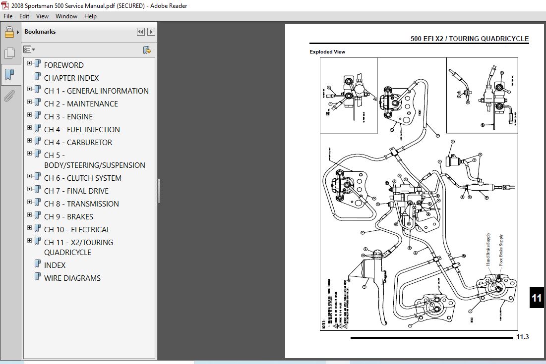
CH 11 – X2/TOURING QUADRICYCLE 387
500 EFI X2 / TOURING QUADRICYCLE BRAKE SYSTEM 388
Overview 388
Exploded View 389
500 EFI X2 / TOURING QUADRICYCLE STEERING POST AND LOCK 390
Steering Assembly Exploded View 390
500 EFI QUADRICYCLE EMISSIONS SYSTEM 391
Overview 391
500 QUADRICYCLE ELECTRICAL 392
Turn / Hazard Signal Diagram 392
INDEX 393
WIRE DIAGRAMS 399
VIDEO PREVIEW OF THE MANUAL:

IMAGES PREVIEW OF THE MANUAL:

PLEASE NOTE:
- This is the SAME exact manual used by your dealers to fix your vehicle.
- The same can be yours in the next 2-3 mins as you will be directed to the download page immediately after paying for the manual.
- Any queries / doubts regarding your purchase, please feel free to contact [email protected]


Leandro Ryker –
It was easy, quick, and convenient-what I was looking for. The quality of the product could have been a bit better but overall, it works.