

BT VCE150A 150AC 125ASF 125ACSF C15 Service Manual 227761-040 – PDF DOWNLOAD
DESCRIPTION:
BT VCE150A 150AC 125ASF 125ACSF C15 Service Manual 227761-040 – PDF DOWNLOAD
(serial number: 564221-919698)
Valid from serial number: 919699-
Order number: 227761-040
Presentation of the truck – M2 (t-code 712) :
Ergonomics :
- VCE150A/VCE150AC has been designed to meet the highest requirements on efficient VNA equipment in terms of high performance, excellent ergonomics, and continuous availability. The truck has been designed to make both pallet handling and order picking highly ergonomic.
- The mast, cab front and fork carriage are designed to promote good visibility both to the front and rear, thus allowing safe and efficient handling of goods. The operator’s position can be easily adapted to allow a comfortable working position with all controls and information panels within easy reach. Emphasis has been placed on an ideal work environment for the operators with low noise and whenever possible a low stress level to enable them to perform at their best while at the same time feeling well.
Performance :
The truck uses articulated steering allowing smooth manoeuvering both in and outside narrow aisles. It can be ordered both for rail guided and wire guided narrow aisle systems. It has four wheel and two drive motors which together with the rigid mast afford safe and efficient load handling even for high lifts.
- Thanks to its high stability, the maximum travel speed of 10 km/h can be used even for high cabin heights, adding to the high performance and low operational cost of the truck.
- It is equipped with a newly developed fork unit that includes design solutions, which are new for this type of truck. Traversing is controlled by a hydraulic motor and synchronous drive belts allowing close to silent traversing and a design that requires almost no maintenance at all.
TABLE OF CONTENTS:
BT VCE150A 150AC 125ASF 125ACSF C15 Service Manual 227761-040 – PDF DOWNLOAD
1- Content 3
2- Presentation of the truck – M2 (t-code 712) 19
2 1 Ergonomics 19
2 2 Performance 19
2 3 Electrical system 20
2 3 1 Intended application of the truck 20
2 3 2 Forbidden application of the truck 20
2 4 Truck data 21
2 5 Truck dimensions 24
2 6 Identification plate 26
2 7 Capacity plate 26
2 8 Additional plates (VNA) 27
2 9 Modification plate 27
2 10 Identification plate, mast 27
2 11 Main components 28
2 12 Warning and information plates and symbols 30
3- Presentation of the truck – M2 (t-code 713) 31
3 1 Intended application of the truck 32
3 2 Prohibited application of the truck 32
3 3 Truck data 33
3 4 Truck dimensions 34
VCE125ASF 35
3 5 Identification plate 38
3 6 Capacity plate 38
3 7 Additional plates (VNA) 38
3 8 Modification plate 39
3 9 Identification plate, mast 39
4- Introduction, maintenance – P1 (t-code 712) 41
4 1 Safety precautions for maintenance work 41
4 1 1 Gas-charged accumulators 43
4 2 Maintenance work to be performed by the operator 43
4 2 1 Maintenance work that may be performed by trained service technicians 43
4 3 Cleaning and washing 44
4 3 1 Exterior cleaning 44
4 3 2 Cleaning the motor compartment 44
4 3 3 Electric components 44
4 4 Secure lifting 45
4 5 Lifting points 46
4 5 1 Lifting the truck 46
5- Maintenance – P1 (t-code 713) 47
5 1 Safety regulations with maintenance work 47
Gas-charged accumulators 48
5 1 1 Maintenance work that is to be carried out by the operator 49
5 1 2 Maintenance work that may be carried out by trained maintenance personnel 49
5 2 Cleaning and washing 49
5 2 1 External cleaning 49
5 2 2 Cleaning the motor compartment 50
5 2 3 Electrical components 50
5 3 Transporting and storing the truck 51
5 3 1 Lifting the truck 51
5 3 2 Towing and transporting a defective truck 51
5 3 3 Storing the truck 52
Battery 52
Hydraulic system 52
Drive unit 52
5 4 Starting after a period of disuse 53
6- Preventive maintenance – P2 (t- code 712) 55
6 1 Maintenance schedule 55
7- Preventive maintenance – P2 (t-code 713) 63
8- Oil and grease specifications – P3 (T-code 712) 67
9- Oil and grease specification – P3 (t-code 713) 69
10- Tools – P4 71
10 1 Super Seal contact 71
10 1 1 AMP connector 72
10 1 2 Diverse tools 73
11- Chassis – 0000 Truck installation 79
11 1 General 79
11 2 Tool list 79
11 3 Unloading the truck 80
11 3 1 Unloading a standing truck 81
Drive the truck off the trailer 81
Towing the truck off the trailer 81
Unloading with a counterweight truck 82
11 3 2 Unloading a truck lying down 83
Unloading the truck from a lorry using a counter balance truck 84
11 3 3 Unloading the truck using cranes 85
11 3 4 Erecting the truck 88
11 3 5 Final assembly 92
11 3 6 Assembly of the initial mast 92
11 4 Preparations for commissioning 93
11 5 Installation in narrow aisle 94
11 5 1 General 94
11 5 2 Rail-guided truck 94
11 5 3 Wire-guided truck 94
12- General tightening torque – 0400 95
12 0 1 Galvanised, non oiled bolts 95
12 0 2 Untreated, oiled bolts 95
12 1 Tightening torque 96
13- Electric pump motor – 1710 1 97
13 1 General 97
13 2 Disassembled pump motor 97
13 3 Disassembly and assembly of the pump motor 98
13 3 1 Disassembly 99
13 3 2 Assembly 100
13 4 Replacing the ball bearing 101
13 4 1 Disassembly 101
13 4 2 Assembly 102
13 5 Assembly instruction for the external temperature sensor 103
14- Electric pump motor – 1710 2 107
14 1 General 107
14 2 Disassembled pump motor 107
14 2 1 Connection 107
14 3 Disassembly and assembly of the pump motor 108
14 3 1 Disassembly 109
14 3 2 Assembly 110
14 4 Replacing the ball bearing 110
14 4 1 Disassembly (D side) 111
14 4 2 Assembly 111
14 4 3 Disassembly (N side) 111
14 4 4 Assembly (N side) 112
14 4 5 Carbon brushes and carbon brush-rocker 112
New carbon brushes must always be smoothened beforehand 112
Commutator 112
Truing the commutator 113
15- Electric drive motor – 1760 115
15 1 General 115
15 2 Disassembled drive motor 116
15 3 Disassembly and assembly of the drive motor 117
15 3 1 Disassembly of the drive motor 117
Disassemble the gear wheel 117
Disassemble the brake 117
15 3 2 Assembly of the drive motor 118
Assemble the brake 118
Assemble the gear wheel 118
15 4 Replacing the ball bearing 119
N side 119
D side 119
15 4 1 Assembly 120
N side 120
D side 120
15 5 Assembly instruction for the external temperature sensor 121
16- Drive unit/gear – 2550 125
16 1 General 125
16 2 Components/data of the drive unit and gear 125
16 2 1 Component identification 126
16 2 2 Technical data 128
16 2 3 Dismantled gear 128
16 3 Replacing the drive motor/drive gear 129
16 3 1 Dismantling of drive unit from truck 129
16 3 2 Fitting the drive unit in truck 129
16 3 3 Dismantling the drive motor and the gear 130
16 3 4 Fitting the drive motor and the gear 130
16 4 Oil level check/replacement 131
16 4 1 Checking/filling of oil 131
16 4 2 Oil replacement 131
16 5 Repairs 132
16 5 1 Replacing the drive shaft sealing ring 133
Dismantling 133
Assembly 133
16 5 2 Leakage from the top cover 134
16 5 3 Leakage from the lower cover 134
16 5 4 Replacing the wheel bolt 135
17- Travel brake system – 3100 137
17 1 General 137
17 2 Operating description 137
17 2 1 Releasing the accelerator 138
17 2 2 Travel direction selector 138
17 2 3 Pressing down the brake pushbutton 138
17 2 4 Parking brake 138
17 2 5 Emergency braking 138
17 3 Electromechanical disc brake, drive motor 140
17 3 1 Assembling 140
17 3 2 Dismantling 141
17 3 3 Inspection 141
17 3 4 Assembling 141
17 4 Maintenance 141
17 4 1 Adjusting the play 142
17 4 2 Wear 142
17 4 3 Check the braking force 143
17 5 Multiple disc brake, support arm 143
17 5 1 Assembling 144
17 5 2 Dismantling 145
17 5 3 Inspection 146
17 5 4 Assembling 146
17 6 Maintenance 146
17 6 1 Adjusting the play 147
18- Drive wheel – 3530 149
18 1 General 149
18 2 Dismantling the drive wheel 149
18 3 Assembling the drive wheel 149
19- Fork/support arm wheel – 3550 151
19 1 Dismantling the wheel 151
19 2 Assembling the wheel 153
300 mm wheel with brake and 350 mm wheel 153
19 3 Dismantling/assembling the wheel bearings 154
19 3 1 300 mm wheel with brake and 350 mm wheel 154
Dismantling the bearing 154
Assembling bearings 155
21- Hydraulic system – 6000 475
21 1 General 475
21 1 1 Symbols 476
21 2 Cabin lifting 478
21 2 1 General 478
21 2 2 Cabin lifting – S44 closed 478
21 2 3 Cabin lowering – S70 closed 478
21 2 4 AC hydraulic unit, components 479
21 2 5 Hydraulic flow diagram, cabin lifting 481
Symbol list, chassis 482
21 2 6 B cylinder system 483
Hydraulic flow diagram, B cylinder system 484
Symbol list, B cylinder system 484
21 3 Fork units and steering 485
21 3 1 General 485
21 3 2 Hydraulic flow diagram, DC system (t-code 712) 486
21 3 3 Hydraulic diagram (t-code 713) 487
Symbol list, fork unit and steering 488
Turret head fork unit valve (t-code 712) 489
21 3 4 Shuttle fork valve blocks (Tcode 713) 490
21 3 5 Fork rotation (t-code 712) 491
21 3 6 Traversing movement 491
21 3 7 Fork lifting 492
21 3 8 Fork lowering 492
21 3 9 Steering 493
Steering valve 494
21 4 Extra hydraulic function (T-code 712) 495
21 4 1 Valves used for the extra hydraulic functions 495
Electrical connection 495
21 4 2 Hydraulic diagram, extra hydraulic function (t-code 712) 496
22- Hydraulic pump – 6140 497
22 1 General 497
22 2 Replacing the hydraulic pump 498
22 2 1 Dismantling 498
22 2 2 Assembling 500
23- Main mast and mast – 7100 501
23 1 Setting the cab and mast stoppers 501
23 1 1 Cab stoppers 501
23 1 2 Setting the cab stoppers 502
23 1 3 Mast stoppers 505
24- Main lift chain system – 7120 507
24 1 General 507
24 2 Checking the chain setting 507
24 3 Chain inspection 507
24 3 1 Noise 507
24 3 2 Surface rust 507
24 3 3 Rusty links 507
24 3 4 Stiff links 508
24 3 5 Bolt rotation 508
24 3 6 Loose bolts 508
24 3 7 Outline wear 509
24 3 8 Stretching 510
24 3 9 Damage 510
24 3 10 Damaged discs 511
24 3 11 Damaged bolts 511
24 3 12 Dirty chain 511
24 4 Cleaning 511
24 5 Lubrication 512
25- Initial mast/Turret head fork unit – 7200 (t-code 712) 513
25 1 General 513
25 2 Assembly/disassembly of the initial mast 514
25 2 1 Mast assembly 514
25 2 2 Installation of belts on a new truck 518
25 2 3 Installing the hydraulic hose and electric cabling 520
25 2 4 Mast disassembly 521
25 3 Inspection and replacement of belts used for fork traversing 522
25 3 1 Inspection 522
Inspecting the belt condition 522
25 3 2 Replacing the belt 523
Disassembly of the belt 523
Installing the belt 524
25 3 3 Checking belt tensioning 526
Belt tension meter 213973 526
“Span” measurement of the traversing arm 526
Tension measurement of the traversing belt 527
Tension measurement of the drive belt 527
25 4 Friction plate adjustment 529
26- Shuttle fork unit – 7800 (t-code 713) 531
26 1 Assembling shuttle forks 531
26 2 Maintenance 533
26 2 1 Maintenance schedule 534
26 2 2 Lubrication 536
Oil and grease specification 536
26 2 3 Adjustment of chains 537
Adjustment of fork chains 537
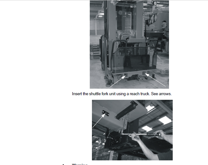
26 3 Replacement of shuttle fork unit 540
27- Wire guidance equipment – 8200 543
27 1 General 543
27 2 Generator 544
27 2 1 Technical data 544
28- Control/computer equipment – 8700 545
28 1 General 545
28 2 Connection 545
28 2 1 Specifications 545
28 3 Truck software management on the PC 546
28 3 1 Downloading the software package via the network 546
28 4 Connecting to the truck 549
28 4 1 Connecting to the truck 550
28 4 2 Menu window tree 551
28 4 3 Disconnection 551
28 5 Menus 552
28 5 1 File menu 552
“Open package” 553
“Save truck report” 554
“Save output window to file” 555
“Save parameter setup to file” 556
“Update parameter setup in truck” 557
“Save height pre-selection setup to file” 558
“Update height pre-selection from file” 558
28 5 2 View menu 559
“Read configuration” 559
“Update” 559
“Run” 560
“Abort communication” 560
28 5 3 Tools menu 561
“Log In” 561
“Log In Production mode” 561
“Log Out” 561
“Read error log” 562
“Erase error log” 564
“Set hour meters” 565
“Set all parameters to default” 566
“Download package” 566
28 5 4 Option menu 567
“Program settings” 567
28 6 “Download package”, Function for firmware downloading 568
28 6 1 Normal firmware download 569
Errors encountered during downloading 571
28 6 2 “Emergency download” 572
28 7 Using the menu tree to verify/ change parameters and perform diagnostics 574
28 7 1 “Software” 574
28 7 2 “Parameters” 575
28 7 3 Diagnostics/troubleshooting 577
“Digital IO” 577
“Analog IO” 578
Example: Diagnostics procedure for the Initial lift function 578
28 8 Installation 585
28 8 1 Installation of TruckCom SE on a PC 586
Downloading TruckCom SE via the Internet 586
Installing/updating TruckCom SE on the PC 588
28 8 2 Necessary changes in Windows XP and Windows 2000 for TruckCom SE 590
Changes in Windows® Control Panel 594
28 8 3 In case of communication errors with the CAN 596
28 8 4 To uninstall 596
29- Height pre-selection – 9390 597
29 1 General 597
29 2 Parameters 597
29 2 1 MCU parameters 597
Parameter 159 598
29 3 Programming 598
29 3 1 Programming a level 599
”Collection level” 599
”Leaving level” 600
“Order picking level” 600
Erasing programmed levels 600
Changing the programmed level 601
29 3 2 Operation/Automatic operations 601
General 601
Collecting a load 601
Depositing a load 603
Order picking 604
SM VCE+SF_5000 pdf 0
20- Electrical system – 5000 157
20 1 General 157
20 1 1 Terminology 159
20 1 2 Truck firmware applications 159
20 1 3 Communication 159
CAN communication 159
AUX serial interface 160
20 2 Main Computer Unit, MCU (A5) 160
20 2 1 General 161
The MCU has the following functions: 162
20 2 2 Voltage feed 162
20 2 3 Battery negative 162
20 2 4 Electric connectors 162
20 2 5 Internal status monitoring 162
20 2 6 External inputs and outputs 163
X130 connector 163
X131 connector 165
X132 connector 167
20 2 7 Installing a new card in the truck 168
20 2 8 Programming the MCU 168
20 3 Fork computer unit, FCU (A4) 169
20 3 1 General 169
The FCU has the following functions: 169
20 3 2 Voltage feed 170
20 3 3 Battery negative 170
20 3 4 Electric connectors 170
20 3 5 External inputs and outputs 171
Connector 171
20 3 6 Installing a new card in the truck 173
20 3 7 Programming 173
20 4 Integrated Control Panel, ICP (A16) 174
20 4 1 General 174
The ICP has the following functions: 175
20 4 2 ICP modules 176
Left section 177
Right section 177
Display/keypad section (Std version) 177
Logic card 177
20 4 3 Voltage feed 177
20 4 4 Battery negative 178
20 4 5 External inputs and outputs 178
X100 connector 178
X101 connector 179
X102 connector 180
X103 connector 181
X104 connector 181
X106 connector 182
X107 connector 182
20 4 6 Installing a new ICP in the truck 182
20 4 7 Programming 182
20 5 AC regulators, ACTL (A1), ACTR (A31) and ACH (A2) 183
20 5 1 General 183
20 5 2 Connection terminal and terminal pillars 184
20 5 3 Technical data 185
20 5 4 Installing a new frequency converter in the truck 185
20 5 5 Programming 185
20 5 6 Maintenance 186
20 5 7 Safety 186
20 5 8 Cleaning 186
20 6 DC regulator, DCHI (A32) 187
20 6 1 General description 187
20 6 2 Connection terminal and terminal pillars 188
20 6 3 Technical data 189
20 6 4 Installing a new transistor panel 189
20 7 Parameters 190
20 7 1 Diagnostics and troubleshooting 190
Displaying errors codes and error logging 190
Error codes, troubleshooting 191
Resetting errors 191
20 7 2 Maintenance 192
20 7 3 Safety 192
20 7 4 Cleaning 192
20 7 5 Hand-held terminal 1307 193
20 7 6 Using the hand-held terminal 195
20 7 7 Viewing and adjusting parameters 196
Using the MORE INFO PROGRAM MODE 196
20 7 8 SPECIAL PROGRAM MODE 197
20 7 9 Using the TEST mode 197
20 7 10 Using the DIAGNOSTICS MODE 198
20 7 11 SPECIAL DIAGNOSTICS MODE 198
20 8 Electrical system, overview 199
T-code 712 200
T-code 713 203
20 9 List of symbols and electric circuit diagrams 204
20 9 1 List of symbols 204
20 9 2 Electrical wiring diagrams (T-code 712) 206
20 9 3 Electrical wiring diagrams (T-code 713) 236
20 10 Component list 265
20 10 1 Placement of components 272
Picture 1 272
Picture 2 273
Picture 3 274
Picture 4 275
Picture 5 276
Picture 6 277
Picture 7 278
Picture 8 279
Picture 9 280
20 10 2 Cabling contacts 281
20 11 Functional description, General 283
20 12 Functional description, starting, driving, steering and braking 284
20 12 1 Battery connected, truck switched off 284
20 12 2 Log-in / Start-up 285
Log-in 285
Start-up process 286
Warnings during start-up 287
Critical faults during start-up 288
20 12 3 Log-out / Switch-off 289
Log-out 289
20 12 4 Presence verification 290
Open cabin gates 290
Closed cabin gates 290
20 12 5 Selecting the drive direction / Driving 290
Forward travel 291
Reverse travel 291
Motor control (ACTL, ACTR) 291
20 12 6 Emergency driving mode 292
20 12 7 Travel speeds 293
Optipace 293
Other travel speed reductions 293
Travel speeds outside narrow aisles with forks in the “home position” 295
Travel speeds for trucks in rail-guided narrow aisles 296
Travel speeds for trucks in wire-guided narrow aisles 298
20 12 8 Steering 298
Safety monitoring 299
Steering wheel 300
Free driving mode 301
Rail-guided narrow aisle mode 302
Wire-guidance mode 302
20 12 9 Braking 303
Safety monitoring 303
Automatic braking 304
Reversing/Motor braking 304
Braking with the brake button (S48) 305
Right dead man’s handle released (S101) 305
End-of-aisle braking/End-of-aisle stopping (options) 306
Personal protection system (PPS) 307
Emergency switch-off (ESO) 307
Parking brake 308
20 13 Electrical description of the hydraulic functions 308
20 13 1 Allowed combined functions 309
20 13 2 Monitoring and functional limitations 310
Monitoring 310
Safety limitations 310
20 13 3 Slack chain guard 312
20 13 4 Height measurement 312
Safety monitoring 313
20 13 5 Cabin lifting 314
Safety monitoring 315
20 13 6 Special height (lift limiter function) 316
20 13 7 Cabin lowering 317
Safety monitoring 318
20 13 8 Special function with cab lifting/ lowering and forks set straight ahead 319
20 14 Turret head unit (T-code 712) 320
Safety monitoring 321
Automatic switching of the turret head fork unit’s functions 322
Fork lifting/lowering 322
Measuring the load weight 325
Side shifting/traversing of the forks 326
Fork rotation 328
20 14 1 Auto rotation 330
20 14 2 Miscellaneous electrical functions 332
Warning lamp 332
Personal protection system (PPS) 332
20 14 3 Narrow aisle ID system 333
20 14 4 Alternative “narrow aisle system” 334
Narrow aisle type 334
20 15 Shuttle fork unit (t-code 713) 336
20 15 1 Traversing of the forks 336
Functional description 336
20 15 2 Fork lifting/lowering 338
Lifting 338
Lowering 339
Measuring the load weight 340
20 16 Wire guidance 341
20 16 1 General 341
20 16 2 Wire guidance components 341
MCU 341
Antennas, W1 and W2 341
Installing a new antenna 343
Steering angle sensor R7 343
Activation switch 344
Narrow aisle mode 344
Narrow aisle type 344
20 16 3 Functional description 346
Run mode 346
20 17 Display 348
20 17 1 Normal mode 348
20 17 2 Information mode 351
20 18 Calibration Turret Head (t-code 712) 353
20 18 1 Calibration mode 353
Calibration of the ICP controls – “CONTROLS” 354
Calibration of steering – “STEERING” 355
Calibration of wire guidance – “WIRE” 356
Calibration of the turret head fork unit functions – “FORKS” 357
Calibration of weight indication – “WEIGHT” 359
Calibration of B cylinder pressure – “PRESSURE” 360
20 19 Calibration Shuttle fork (t-code 713) 361
20 19 1 Calibration of Shuttle fork 361
Calibration of weight indication – “WEIGHT” 362
Learn status codes – FCU 363
20 20 Parameters 364
20 20 1 Accessing parameters 365
Operator parameters (service key not inserted) 365
20 20 2 Operator parameters (operators 1-10) 366
Parameter 1 366
Parameter 2 366
Parameter 3 366
Parameter 4 366
Parameter 5 367
Parameter 6 367
Parameter 7 367
Parameter 10 367
20 20 3 Truck parameters 368
20 20 4 MCU parameters 370
Basic parameters 370
Parameter 101 375
Parameter 102 375
Parameter 103 375
Parameter 104 376
Parameter 105 376
Parameter 106 376
Parameter 107 376
Parameter 108 376
Parameter 109 376
Parameter 110 376
Parameter 111 376
Parameter 112 376
Parameter 113 376
Parameter 114 377
Parameter 115 377
Parameter 116 377
Parameter 117 377
Parameter 118 377
Parameter 119 – 125 377
Parameter 126 377
Parameter 127 378
Parameter 128 378
Parameter 129 379
Parameter 130 379
Parameter 131 379
Parameter 132 379
Parameter 133 379
Parameter 134 379
Parameter 135 379
Parameter 136 379
Parameter 137 380
Parameter 138 380
Parameter 139 380
Parameter 140 380
Parameter 141 380
Parameter 142 380
Parameter 143 382
Parameter 144 383
Parameter 145 384
Parameter 146 384
Parameter 147 384
Parameter 148 384
Parameter 149 384
Parameter 150 384
Parameter 151 384
Parameter 152 385
Parameter 153 385
Parameter 154 – 156 385
Parameter 157 385
Parameter 158 386
Parameter 159 386
Parameter 160 386
Parameter 161 386
Parameter 162 386
Parameter 163 386
20 20 5 Wire guidance parameters: 387
Parameter 165 387
Parameter 166 388
Parameter 167 388
Parameter 168 388
Parameter 169 388
Parameter 170 389
Parameter 171 389
Learned calibration values, steering 390
Parameter 186 390
Parameter 187 391
Parameter 188 391
Parameter 189 391
Parameter 190 391
Parameter 191 391
Parameter 192 391
Parameter 193 391
Parameter 194 392
Learned calibration data, wire guidance 393
20 20 6 FCU parameters (t-code 712) 394
Basic parameters, turret head fork unit 394
Parameter 400 395
Parameter 401 395
Parameter 402 395
Parameter 403 396
Parameter 404 396
Parameter 405 396
Parameter 406 396
Parameter 407 396
Parameter 408 396
Parameter 409 396
Parameter 410 396
Parameter 411 396
Parameter 412 396
Parameter 413 396
Parameter 414 397
Parameter 415 397
Parameter 416 397
Parameter 417 397
Parameter 418 397
Parameter 419 397
Parameter 420 397
Parameter 421 397
Parameter 422 397
Parameter 423 397
Parameter 424 397
Parameter 425 397
Parameter 426 398
Parameter 427 398
Parameter 428 398
Learned calibration data, turret head fork unit 398
Parameter 450 399
Parameter 451 400
Parameter 452 400
Parameter 453 400
Parameter 454 400
Parameter 455 400
Parameter 456 400
Parameter 457 400
Parameter 458 400
Parameter 459 400
Parameter 460 400
Parameter 461 401
Parameter 462 401
Parameter 463 401
Parameter 464 401
Parameter 465 401
Parameter 466 401
Parameter 467 401
Parameter 468 401
Parameter 469 401
Parameter 470 402
Parameter 471 402
Parameter 472 402
Parameter 473 402
Parameter 474 402
Parameter 475 402
Parameter 476 402
Parameter 477 402
20 21 Parameters Shuttle fork (t-code 713) 403
20 21 1 Service Parameters (t-code 713) 403
20 21 2 Learned data (t-code 713) 405
20 21 3 ICP parameters 406
Parameter 500 407
Parameter 501 407
Parameter 502 – 505 407
Parameter 507 408
Parameter 508 408
Parameter 509 408
Parameter 510 408
Parameter 530 – 539 408
Parameter 540 – 549 408
20 22 Warning and error codes 409
20 22 1 Error handling 409
Error grouping 409
Error recording 410
20 22 2 Safety logics 411
20 23 Warning and error codes 413
20 23 1 ICP, code group 1 413
ICP warning codes 413
ICP error codes 419
20 23 2 MCU, code group 2 423
MCU warning codes 423
MCU error codes 425
20 23 3 Drive system, code group 3 432
Drive system – warning codes 432
Drive system – error codes 436
20 23 4 Cabin lift system, code group 4 443
Cabin lift system – warning codes 443
20 23 5 Steering system, code group 5 449
Steering system – warning codes 449
20 23 6 Initial lift and turret head fork unit systems, code group 6 (t-code 712) 462
Initial lift and turret head fork unit systems – warning codes 462
20 23 7 Shuttle Fork system (including FCU cautions) – code group 6 (t-code 713) 469
IMAGES PREVIEW OF THE MANUAL:
VIDEO PREVIEW OF THE MANUAL:

PLEASE NOTE:
- This is the same manual used by the DEALERSHIPS to SERVICE your vehicle.
- The manual can be all yours – Once payment is complete, you will be taken to the download page from where you can download the manual. All in 2-5 minutes time!!
- Need any other service / repair / parts manual, please feel free to contact us at heydownloadss @gmail.com . We may surprise you with a nice offer
S.V


