

Massey Ferguson MF 8700 S Series 8727S 8730S 8732S 8735S 8737S 8740S Dyna-VT Operator’s Manual – PDF DOWNLOAD
DESCRIPTION:
Massey Ferguson MF 8700 S Series 8727S 8730S 8732S 8735S 8737S 8740S Dyna-VT Operator’s Manual – PDF DOWNLOAD
MF 8700 S – Operation
Efficient and Exclusive versions
MF 8727 S
MF 8730 S
MF 8732 S
MF 8735 S
MF 8737 S
MF 8740 S
Part. No : ACT0045040
FOREWORD:
We would like to welcome you to the ever-growing number of people who own a Massey Ferguson tractor; people who appreciate quality. We are proud of every tractor that leaves our factories, each being technically advanced and of a high quality. This Operator’s Manual contains the specifications for your new tractor. Please ensure that all operators read the instructions and follow them carefully. The pages that follow contain vital information on your tractor; please read them carefully. This Operator’s Manual contains the specifications for your new equipment. Please ensure that all operators read the instructions and follow them carefully. This will allow you to benefit from a long service life with complete safety and peace of mind.
- The pages that follow contain vital information about your new equipment; please read them carefully. Your Massey Ferguson dealer will guarantee you quality servicing and will provide you with all the assistance you need. When it comes to servicing, remember that your dealer knows your tractor best and that he wants you to be completely satisfied. Your Massey Ferguson dealer will guarantee you all the assistance you need.
- Please leave this Operator’s Manual in the tractor if resold. The subsequent owner will need the information it contains. All information and specifications in this manual are up to date at the time of publication. However, our ongoing policy to improve our products obliges us to reserve the right to make alterations at any time without notice.
- Please note that this manual relates to all models and refers to both standard and optional equipment. You may therefore find details relating to equipment that is not fitted on your tractor. This Operator’s Manual complies with European Directive 2 0 0 3/ 3 7 EC which applies to all vehicles with a maximum speed of less than or equal to 4 0 km/h. This Operator’s Manual complies with the German Road Traffic Licensing Regulations (StVZO) Directive which applies to all vehicles with a maximum speed greater than or equal to 4 0 km/h.
Operator’s Manual :
The purpose of this manual is to enable the owner and the operator to operate the tractor appropriately under normal conditions of use. Providing they follow the instructions carefully, the tractor will give many years of service in the Massey Ferguson tradition. Use for any other activity (particularly forestry work) is considered to be contrary to the intended use.
- The commissioning of equipment by the Massey Ferguson dealer on the user’s premises enables the dealer to ensure that these operating and service instructions are properly understood. Always consult the Massey Ferguson dealer if there is any part of this manual that you do not understand. It is important that these instructions are understood and followed.
- This manual does not cover all operation and safety instructions relevant to the implements and accessories that may be fitted at the time of tractor delivery or later. It is essential that operators use and understand the Operator’s Manuals relating to these implements and accessories. This chapter in the Operator’s Manual highlights certain basic safety-related situations that may be encountered during normal operation and servicing of the tractor and provides the information needed to handle these situations.
- This chapter supplements any safety instructions given in other chapters of this manual. It may be necessary to take additional precautions, depending on the implements and accessories used and the working conditions on-site or in the service area. Massey Ferguson can under no circumstances exercise direct control over the commissioning, operation, inspection, lubrication, or servicing of the tractor. It is therefore YOUR responsibility to take suitable safety precautions in such areas.
TABLE OF CONTENTS:
Massey Ferguson MF 8700 S Series 8727S 8730S 8732S 8735S 8737S 8740S Dyna-VT Operator’s Manual – PDF DOWNLOAD
1 Tractor identification 13
1 1 Locating serial numbers 15
1 1 1 Locating serial numbers 1 5
1 2 Your tractor identification details 17
1 2 1 Your tractor identification details 17
2 Safety instructions and safety points – Warranty 19
2 1 Introduction 21
2 1 1 Introduction – Safety instructions 2 1
2 2 Safety – Symbols and terms 23
2 2 1 Safety – Symbols and terms 2 3
2 3 Safety decals and instructions 24
2 3 1 Checking and replacing the safety decals and instructions 2 4
2 3 2 Presentation and location of the safety decals and instructions 2 5
2 4 General safety instructions 29
2 4 1 Awareness of the safety instructions and symbols 2 9
2 4 2 Operator familiarity in the use of the tractor 2 9
2 4 3 Filling the fuel tank 3 0
2 4 4 Mounting and dismounting the operator’s seat 3 0
2 4 5 Mandatory procedure before dismounting the tractor 3 1
2 5 Special instructions 32
2 5 1 Specific recommendations for agricultural and forestry tractors 3 2
2 6 Special safety instructions for preparing the tractor for use 34
2 6 1 Protective clothing 34
2 6 2 Activated carbon filter information 34
2 6 3 Safety devices and items 37
2 6 4 Checking the tractor 37
2 7 Specific safety instructions for starting the tractor 39
2 7 1 Protection of persons other than the operator 3 9
2 7 2 Start up safely 3 9
2 7 3 Starting the tractor with jump start cables 4 0
2 7 4 Checks to be carried out after start-up 4 1
2 8 Specific safety instructions for using the tractor 42
2 8 1 General instructions 4 2
2 8 2 Protection of persons other than the operator 4 3
2 8 3 Overturning 4 3
2 8 4 Tractor towing 4 6
2 8 5 Regulatory data on maximum permitted trailed weights 4 6
2 8 6 Road use 4 8
2 8 7 Instructions and Legislation for the Towing of Implements 4 9
2 8 8 Parking brake 5 0
2 8 9 Emergency hand brake (on models fitted with the ParkLock option) 5 1
2 8 10 Power take-off 5 1
2 8 1 1 Implements 5 2
2 8 12 Front-end loader 54
2 9 Specific safety instructions for servicing the tractor 56
2 9 1 Pollution warning to observe when servicing the tractor 5 6
2 9 2 General instructions 5 6
2 9 3 Handling instructions 5 7
2 9 4 Special instructions for cleaning the tractor 5 9
MF 8700 S – Operation
ACT0045040
Table of contents
2 10 Protective structures 60
2 10 1 Protective structures – Use and accreditation 60
2 10 2 Cab 60
2 10 3 Seat belt 60
2 10 4 Instructor seat 61
2 11 Warranty 62
2 1 1 1 General 62
2 1 1 2 Pre-delivery inspection and commissioning on the user’s premises 62
2 1 1 3 Warranty procedure 62
2 1 1 4 Procedure to follow if changing region 62
2 1 1 5 Servicing during and after the warranty period 63
3 Operation 65
3 1 Operator environment 69
3 1 1 Steering console 69
3 1 2 Instrument panel 70
3 1 3 Control unit 77
3 1 4 Pedals 78
3 1 5 Steering wheel 78
3 1 6 Operator presence detector 79
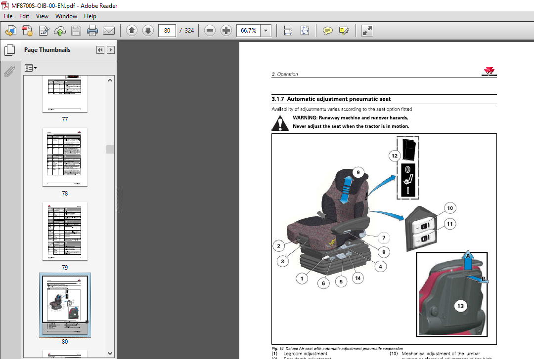
3 1 7 Automatic adjustment pneumatic seat 8 2
3 1 8 Maximum Evolution pneumatic seat 87
3 1 9 Instructor seat 9 3
3 1 10 Right-hand console 9 4
3 1 1 1 Command Control Armrest 9 4
3 1 1 2 Right-hand pillar 97
3 1 1 3 Left-hand console 97
3 1 1 4 Upper console 98
3 1 15 Manual air conditioning 100
3 1 16 Automatic air conditioning 106
3 1 17 Additional heater 1 1 3
3 1 18 Accessories sockets 1 1 3
3 1 19 Emergency exits 1 15
3 1 20 High-visibility roof hatch 1 15
3 1 2 1 Sun visor 1 16
3 2 Setup and Information Screen control screens on the instrument
panel 117
3 2 1 Using the Setup and Information Screen 1 17
3 2 2 Setup and Information Screen screens 1 1 8
3 3 Body 126
3 3 1 Opening the bonnet 1 26
3 3 2 Adjusting the standard external rear-view mirrors 1 26
3 3 2 1 Positioning and extending the arms 1 26
3 3 2 2 Rear-view mirror with manual adjustment 1 27
3 3 2 3 Rear-view mirror with electric adjustment 1 27
3 3 3 Adjusting the double-angle rear-view mirror 1 28
3 3 3 1 Positioning and extending the arms 1 28
3 3 3 2 Rear-view mirror with manual adjustment 1 29
3 3 3 3 Rear-view mirror with electric adjustment 1 29
3 3 4 Adjusting the left-hand step 1 30
3 4 Engine 132
3 4 1 Running-in 1 3 2
3 4 2 Filling with fuel 1 3 2
3 4 3 Start switch 1 3 4
3 4 4 Start-up 1 3 4
3 4 5 Starting the SCR Technology engine in cold weather 1 35
3 4 6 Information on the different operating modes of the SCR Technology 1 37
MF 8700 S – Operation
ACT0045040
Table of contents
3 4 7 Stopping the engine 14 2
3 4 8 Engine speed 14 2
3 4 9 Storing engine speeds 144
3 5 Transmission 146
3 5 1 Presentation of the different driving modes 14 6
3 5 2 Clutch function 14 6
3 5 3 PowerShuttle 14 8
3 5 4 Setting start-up speeds 1 5 0
3 5 4 1 Start speeds 1 5 1
3 5 5 Storage of forward speeds 1 5 1
3 5 6 Lever mode 1 5 3
3 5 7 Pedal mode 1 5 5
3 5 7 1 Pedal Mode in winter conditions (on frozen or snow-covered ground) 1 5 7
3 5 8 Self-propelled mode 1 5 7
3 5 9 Road mode (Hare)/Field mode (Tortoise) 1 5 8
3 5 10 Changing forward speed 1 5 9
3 5 1 1 Tractor towing 16 0
3 5 1 1 1 Towing procedure: 16 0
3 5 12 Tractor limp home mode 16 3
3 5 1 3 Forward speed calibration 16 5
3 6 Brakes 167
3 6 1 Brake pedals 16 7
3 6 2 Instructions and Legislation for the Towing of Implements 16 7
3 6 3 Hydraulic trailer brake 16 8
3 6 4 Pneumatic trailer brake 16 9
3 6 5 Electromechanically controlled brake on the steering column (ParkLock) 17 0
3 6 5 1 ParkLock engaged 17 1
3 6 5 2 Disengagement of the ParkLock 17 1
3 6 5 3 Manual disengagement of the ParkLock 17 1
3 6 6 Emergency hand brake (on models fitted with the ParkLock option) 17 2
3 7 Steering 174
3 7 1 Steering 174
3 8 Front axle 177
3 8 1 Four-wheel drive front axle 17 7
3 8 2 Suspended front axle 178
3 8 3 Permissible load on the front axle 180
3 8 4 Using a scraper 18 3
3 9 Differential lock 185
3 9 1 Differential lock 18 5
3 10 Power take-off 187
3 10 1 Front power take-off 187
3 10 2 Rear power take-off (PTO) 188
3 10 2 1 Selecting the power take-off speed 189
3 10 2 2 Engaging PTO in manual mode: 189
3 10 2 3 Engaging PTO in automatic mode: 190
3 10 3 Economy PTO 19 1
3 10 4 Changing the flanged shaft 19 1
3 10 4 1 Changing the shaft 192
3 10 5 PTO external control 194
3 10 6 Power take-off electronic controls 194
3 10 7 Power take-off protection 19 5
3 11 Linkage 197
3 1 1 1 General Information 197
3 1 1 2 Rear linkage electronic controls 198
3 1 1 3 Rear linkage operation 2 0 0
3 1 1 4 Rear linkage external controls 2 0 5
3 1 1 5 Front linkage 2 0 6
MF 8700 S – Operation
ACT0045040
Table of contents
3 11 6 Top link 2 10
3 11 7 Bottom links 2 12
3 11 8 Lift rods 2 14
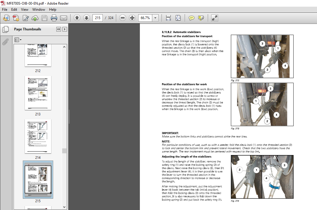
3 11 9 Stabilizers 2 15
3 11 9 1 Stabilizers with manual telescopic adjustment 2 15
3 11 9 2 Automatic stabilizers 2 17
3 11 10 Ball joint support 2 18
3 12 Towing equipment 219
3 12 1 General 2 19
3 12 2 Swinging drawbar 2 2 1
3 12 2 1 Fitting the swinging drawbar 2 2 2
3 12 3 Ball coupling 2 2 3
3 12 3 1 Fitting the K80 ball coupling 2 2 3
3 12 3 2 Hitching the trailer 2 2 4
3 12 3 3 Adjusting the ball coupling 2 25
3 12 4 Drawbar with stud 2 25
3 12 4 1 Fitting the drawbar with stud 2 25
3 12 4 2 Hitching the trailer 2 27
3 12 5 4-wheel trailer clevis hitch 2 27
3 12 6 Pick-up hitch 2 28
3 12 6 1 Lowering the hook 2 28
3 12 6 2 Lifting the hook 2 3 0
3 12 6 3 Fitting the swinging drawbar 2 3 0
3 13 Auxiliary hydraulics 232
3 13 1 General 2 3 2
3 13 2 Description of the hydraulic couplers (Load Sensing) 2 3 2
3 13 3 Use of hydraulic couplers on Closed Center system (Load Sensing) 2 3 4
3 13 4 Auxiliary hydraulics locking/unlocking 2 4 0
3 13 5 Description and use of the cab controls 2 4 1
3 13 6 Description and use of the external controls 2 45
3 13 7 Setting flow rates and time delay 2 45
3 14 Front-end loader function 247
3 14 1 Front-end loader 2 47
3 14 2 Layout of components 2 48
3 14 3 Standard front-end loader connection 2 48
3 14 4 Using the electric joystick of the front-end loader 2 4 9
3 14 4 1 Joystick functions for the front-end loader 2 4 9
3 14 4 2 Floating position 250
3 14 4 3 Front-end loader flow rate control 250
3 14 4 4 3rd and 4th functions 251
3 14 4 5 Arm suspension 251
3 14 4 6 Locking and unlocking accessories 251
3 15 Lighting 253
3 15 1 Main lighting control module 253
3 15 2 Work lights module 254
3 15 3 Daytime running lamps 257
3 15 4 Direction indicators 257
3 16 Suspended cab 261
3 16 1 Suspended cab 2 6 1
3 17 Front tires and track widths 263
3 17 1 Wheel studs 2 6 3
3 17 2 Installation points of the axle stands 2 6 3
3 17 3 Adjusting the front wheel track width 2 6 4
3 17 4 Adjusting the 4WD front axle stops 2 67
3 17 4 1 Oscillation stops 2 67
3 17 4 2 Adjusting the steering angle 2 67
3 17 4 3 Toe-in check 2 68
MF 8700 S – Operation
ACT0045040
Table of contents
3 17 4 4 Adjusting the front fenders Shoe side adjustment on the front axle 2 6 8
3 17 4 5 Adjusting the front fenders Adjusting the height of the support on the
shoe 2 6 8
3 17 4 6 Adjusting the front fenders Adjusting the lateral position of the fender on
the support (two adjustments are possible) 2 6 8
3 17 5 Tires 2 6 9
3 17 6 Tire pressures 2 6 9
3 17 6 1 Model MF 8 7 2 7 S 2 6 9
3 17 6 2 Model MF 8 7 3 0 S 2 7 2
3 17 6 3 Model M F 8 7 3 2 S 2 7 5
3 17 6 4 Model MF 8 7 3 5 S 2 7 8
3 17 6 5 Model MF 8 7 3 7 S 2 8 1
3 17 6 6 Model MF 8 74 0 S 2 8 3
3 18 Rear tires and track widths 287
3 18 1 Wheel studs 2 8 7
3 18 2 Wheel chock(s) (optional) 2 8 7
3 18 2 1 Using the wheel chock 2 8 7
3 18 3 Installation points of the axle stands 2 88
3 18 4 Rear track width with short straight shafts 2 8 9
3 18 5 Rear track width with long straight shafts 2 9 2
3 18 6 Assembly configuration for an external width of 2 5 5 0 mm 2 94
3 18 7 Adjusting the rear wheel track width 2 9 6
3 18 7 1 Adjustment of wheel position on the straight shaft 2 9 6
3 18 7 2 Adjustment of wheel position on the straight shaft 2 9 6
3 19 Dual wheels 298
3 19 1 Dual wheels 2 98
3 19 2 Installation points of the axle stands 2 99
3 19 3 Dual rear wheel track width with short straight shafts 3 0 0
3 19 4 Dual rear wheel track width with long straight shafts 3 0 5
3 20 Ballast 314
3 2 0 1 Liquid ballasting 3 14
3 2 0 2 Front-end weight 3 14
4 Accessories 317
4 1 Cab accessories 319
4 1 1 Cab accessories 3 19
4 2 Engine accessories 320
4 2 1 Engine accessories 3 2 0
4 3 Front axle and steering accessories 321
4 3 1 Front axle and steering accessories 3 2 1
4 4 Power take-off accessories 322
4 4 1 Power take-off accessories 3 2 2
4 5 Linkage accessories 323
4 5 1 Linkage accessories 3 2 3
4 6 Auxiliary hydraulics accessories 324
4 6 1 Auxiliary hydraulics accessories 3 2 4
VIDEO PREVIEW OF THE MANUAL:

IMAGES PREVIEW OF THE MANUAL:
PLEASE NOTE:
- This is the SAME manual used by the dealers to troubleshoot any faults in your vehicle. This can be yours in 2 minutes after the payment is made.
- Contact us at [email protected] should you have any queries before your purchase or that you need any other service / repair / parts operators manual.
S.V


