

Mitsubishi Forklift PBF35N2 Service Manual – PDF DOWNLOAD
FILE DETAILS:
Mitsubishi Forklift PBF35N2 Service Manual – PDF DOWNLOAD
Format: PDF
Language: English
Brand: Mitsubishi
VIDEO PREVIEW OF THE MANUAL:

IMAGES PREVIEW OF THE MANUAL:
DESCRIPTION:
Mitsubishi Forklift PBF35N2 Service Manual – PDF DOWNLOAD
FOREWORD:
This service manual is a guide for servicing lift trucks. The long productive life of your lift truck depends on regular and proper servicing, consistent with the instructions provided in this service manual. Before starting to test, repair or rebuild a lift truck, read the respective sections of this manual carefully and familiarize yourself with all of the components. The descriptions, illustrations and specifications contained in this manual are for lift trucks with serial numbers in effect at the time of printing. The manufacturer reserves the right to change specifications or designs without notice and without incurring obligations. For your convenience, the instructions are grouped by systems as an easy reference. Unauthorized copying and lending of this material is strictly prohibited.
TABLE OF CONTENTS:
Mitsubishi Forklift PBF35N2 Service Manual – PDF DOWNLOAD
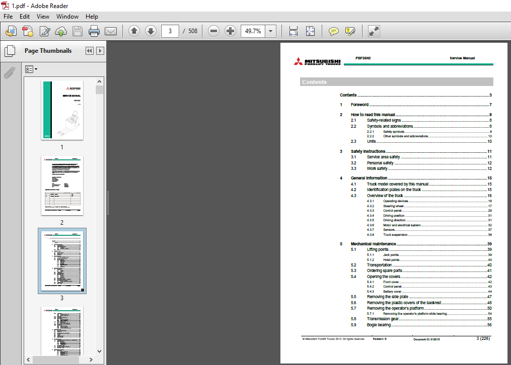
Contents 3
1 Foreword 7
2 How to read this manual 8
2 1 Safety-related signs 8
2 2 Symbols and abbreviations 8
2 2 1 Safety symbols 8
2 2 2 Other symbols and abbreviations 10
2 3 Units 10
3 Safety instructions 11
3 1 Service area safety 11
3 2 Personal safety 12
3 3 Work safety 12
4 General information 15
4 1 Truck model covered by this manual 15
4 2 Identification plates on the truck 15
4 3 Overview of the truck 16
4 3 1 Operating devices 16
4 3 2 Steering wheel 17
4 3 3 Control panel 29
4 3 4 Driving position 31
4 3 5 Driving direction 31
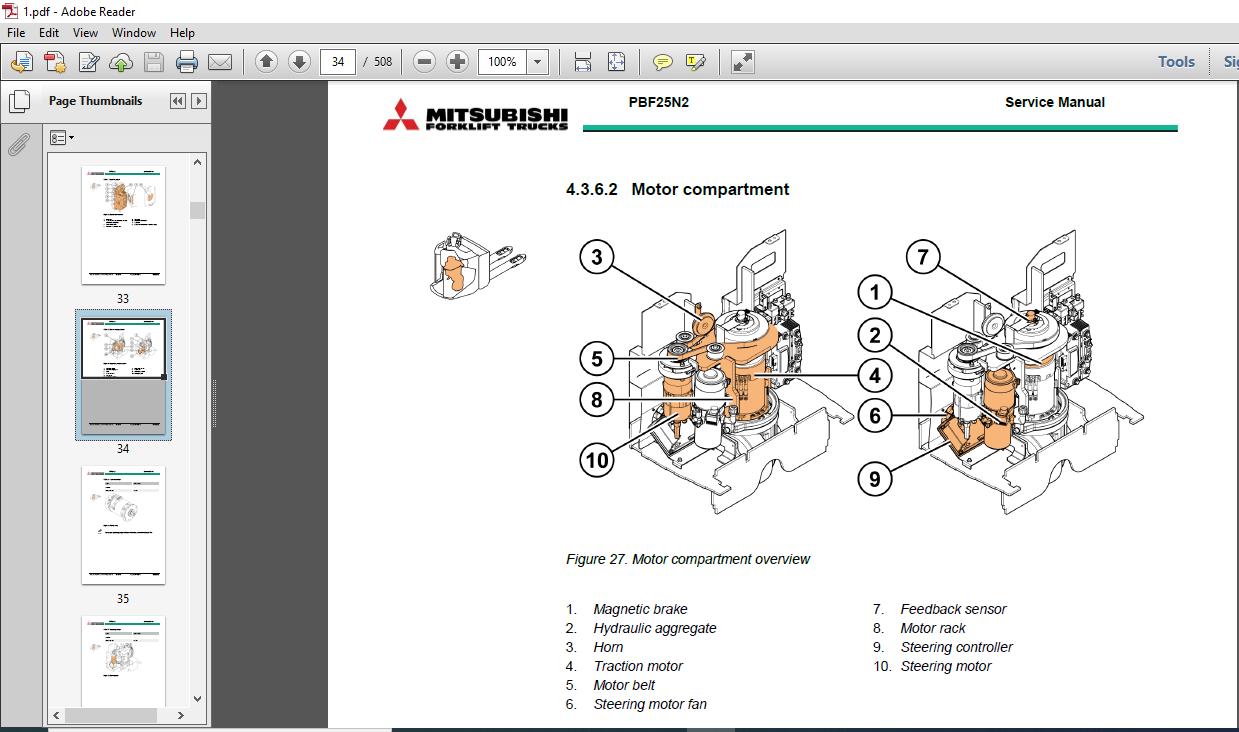
4 3 6 Motor and electrical system 32
4 3 7 Sensors 37
4 3 8 Truck suspension 38
5 Mechanical maintenance 39
5 1 Lifting points 39
5 1 1 Jack points 39
5 1 2 Hoist points 40
5 2 Transportation 40
5 3 Ordering spare parts 41
5 4 Opening the covers 42
5 4 1 Front cover 42
5 4 2 Control panel 43
5 4 3 Battery cover 44
5 5 Removing the side plate 47
5 6 Removing the plastic covers of the backrest 48
5 7 Removing the operator’s platform 50
5 7 1 Removing the operator’s platform slide bearing 54
5 8 Transmission gear 55
5 9 Bogie bearing 56
© Mitsubishi Forklift Trucks 2013 All rights reserved Revision: B Document ID: 618015 4 (226)
PBF25N2 Service Manual
5 10 Traction wheel 56
5 10 1 Disassembly of the traction wheel 57
5 10 2 Assembly of the traction wheel 59
5 11 Load wheels 60
5 12 Lifting system and fork carriage 61
5 13 Castor wheels 64
5 13 1 Disassembly of the castor wheel 64
5 13 2 Adjusting the castor wheels 65
5 13 3 Assembly of the castor wheel 66
5 14 Castor wheel suspension 66
5 14 1 Adjusting the castor wheel suspension 69
5 15 Disassembly of the drive unit suspension 70
5 16 Steering wheel 74
5 16 1 Removing the truck display 74
5 16 2 Removing the steering wheel 76
5 16 3 Replacing the steering wheel’s gas spring 77
6 Electrical operation 79
6 1 Using the schematic diagram 79
6 2 Power source 82
6 3 Safety circuit (emergency stop button) 82
6 4 Key switch 82
6 5 Traction 83
6 6 AC motor operation 83
6 7 Electrical steering 84
7 Battery maintenance 85
7 1 Safety regulations concerning the handling of lead-acid batteries 86
7 2 Battery maintenance 87
7 2 1 Daily maintenance 87
7 2 2 Weekly maintenance 87
7 2 3 Monthly maintenance 87
7 2 4 Annual maintenance 88
7 3 Recharging the battery 88
7 4 Measuring the battery’s specific gravity 91
7 5 Replacing the battery 91
8 Electric system maintenance 94
8 1 Electric panel 94
8 1 1 Removing the controller cover 95
8 1 2 Traction controller 96
8 1 3 Traction controller connectors 96
8 1 4 Steering controller 99
8 1 5 Steering controller connectors 100
8 1 6 Contactors and relays 102
8 1 7 Fuses 104
8 1 8 Accessing the controller fan 105
8 2 Truck connector 107
© Mitsubishi Forklift Trucks 2013 All rights reserved Revision: B Document ID: 618015 5 (226)
PBF25N2 Service Manual
8 2 1 Replacing the truck connector 108
8 3 Motor compartment 109
8 3 1 Removing the drive unit 110
8 3 2 Disassembly of the drive unit 112
8 3 3 Installation of the traction motor 113
8 3 4 Assembly of the splined shaft-hub connection 114
8 3 5 Temperature sensor check 115
8 3 6 HALL sensor 116
8 3 7 Magnetic brake 117
8 3 8 Motor belt 118
8 4 Pump motor 120
8 4 1 Solenoid valve 121
8 5 Sensors 122
8 5 1 Operator’s platform sensor 122
8 5 2 Feedback sensor 124
8 6 Switches and buttons 125
8 6 1 Emergency stop button 125
8 6 2 Key switch 126
8 7 Horn 127
8 7 1 Diode test with a multimeter 128
8 8 Wiring harnesses and cables 128
8 8 1 Installing the traction motor cables 131
9 Electric system adjustments and measurements 133
9 1 Adjusting the electrically powered steering 133
9 2 Insulation resistance test 136
9 2 1 Test voltage 136
9 2 2 Checking the insulation tester 136
9 2 3 Measuring the insulation resistance 137
10 Hydraulic operation 139
10 1 Hydraulic symbols 141
10 2 Hydraulic oil recommendations 143
10 3 Maintenance points of the hydraulic system 143
10 4 Hydraulic aggregate 144
10 4 1 Disassembly of the hydraulic aggregate 145
10 4 2 Disassembly of the oil tank 145
10 4 3 Pressure sensor 146
10 5 Replacing the hydraulic cylinder 148
10 5 1 Replacing the hydraulic cylinder’s slide bearings 150
11 TruckTool Diagnostics 151
12 Parameter descriptions 152
12 1 Traction controller 152
12 2 Pump controller 160
12 3 Steering controller 161
13 Alarm codes 164
© Mitsubishi Forklift Trucks 2013 All rights reserved Revision: B Document ID: 618015 6 (226)
PBF25N2 Service Manual
13 1 Traction controller 164
13 2 Pump controller 174
13 3 Steering controller 180
14 Service data 187
14 1 Special tightening torques 187
14 2 Tightening torque for standard bolts and nuts 188
14 3 Maintenance check list 190
14 4 Lubrication 192
14 4 1 Hydraulic oil 192
14 4 2 Transmission oil 192
14 5 Special tools 193
15 Options 194
15 1 Pallet entry / exit rollers 195
15 1 1 Disassembly of the pallet entry / exit rollers 195
15 2 Load support 196
15 2 1 Installation of the load support 197
15 3 Accessory rack 197
15 3 1 Installation of the accessory rack 198
15 4 Voltage converter 204
15 4 1 Installation of the voltage converter 204
15 5 Battery lock sensor 205
15 5 1 Installation of the battery lock sensor 206
15 5 2 Battery lock sensor functionality check 207
15 6 Battery connector 208
15 6 1 Replacing the battery connector 208
15 7 Charger connector 209
15 7 1 Replacing the charger connector 209
15 8 Quick battery replacement 210
15 8 1 Removing a discharged battery with the battery changing device 210
15 8 2 Installing a recharged battery with the battery changing device 211
15 8 3 Removing the rubber absorbers 212
16 Technical specification 214
17 Index 217
APPENDIX A: Stickers 221
PLEASE NOTE:
- This is the SAME manual used by the dealers to troubleshoot any faults in your vehicle. This can be yours in 2 minutes after the payment is made.
- Contact us at [email protected] should you have any queries before your purchase or that you need any other service / repair / parts operators manual.


