

White MY40 50 60 70 & 80B Forklift Trucks Parts Manual – PDF DOWNLOAD
FILE DETAILS:
White MY40 50 60 70 & 80B Forklift Trucks Parts Manual – PDF DOWNLOAD
Format: PDF
Language: English
Brand: White Forklift
DESCRIPTION:
White MY40 50 60 70 & 80B Forklift Trucks Parts Manual – PDF DOWNLOAD
1-1. SCOPE
1-2. This manual provides instructions on the operation maintenance and overhaul of the MY Series Lift Trucks. Most of the instructions apply to both the MY 40 and the MY 60. Where there are differences, it will be noted
either in the text or the paragraph heading.
1-3. It is strongly recommended that all personnel con-cerned with the various phases of this manual have a thorough knowledge and understanding of the equipment and the instructions pertaining thereof, before performing any procedure with the equipment.
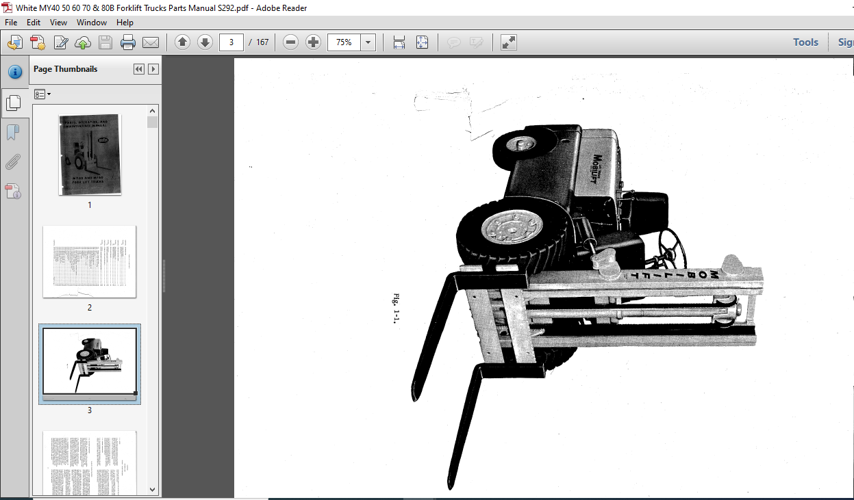
1-4. GENERAL DESCRIPTION
1-5. Due to its design and intended purpose, the equip-ment will be referred to as “lift truck” throughout this manual. Reference to either the right or left sides of the
lift truck are made in respect to the normal direction of travel, which is forward.
1-6. The trucks can be equipped with either a gasoline or LP gas engine. The MY 40 has a capacity of 4000 pounds, the MY 60 a capacity of 6000 pounds, both at a 24 inch load center.
1-7. The lift truck is a completely self-contained vehicle; its power train consisting of a four-cylinder gasoline engine, a hydraulic torque converter, and a multiple disc clutch and power shaft type transmission. All these assemblies are in-tegrally mounted together, forming one compact unit, which in turn drives the front axle differential and the front drive wheels. A gear-type pump, driven from the engine cam-shaft, supplies pressure to the hydraulic system. Electrical components of the lift truck utilize the current supplied
from one 12-volt battery.
1-8. DETAILED DESCRIPTION
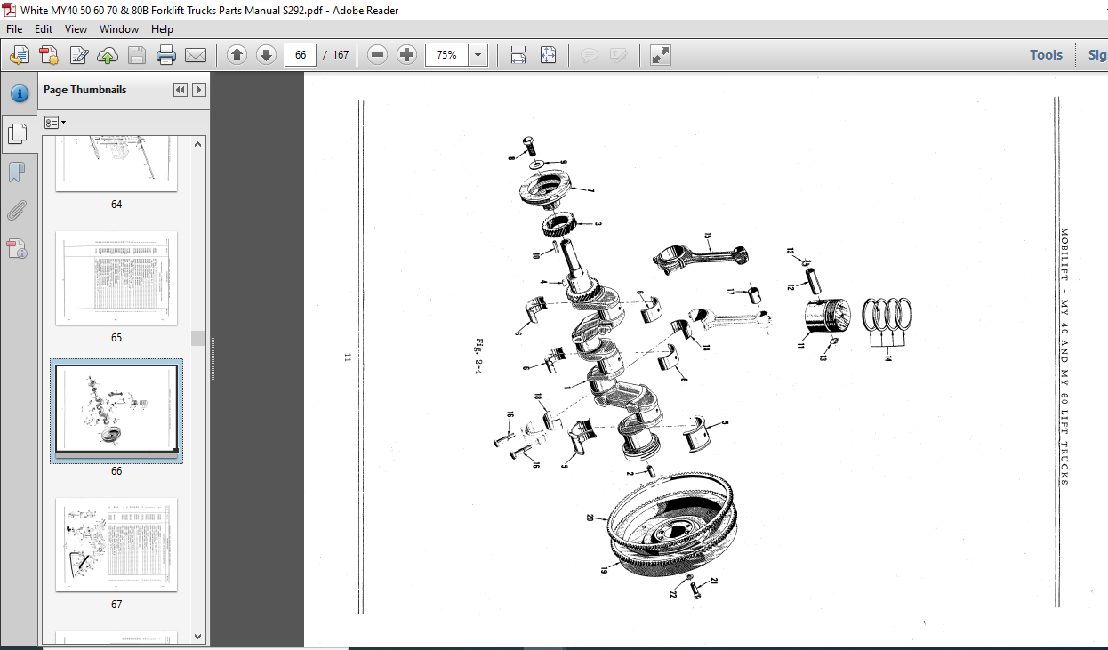
1-9. ENGINE. The engine (figure 1-2) is a four-cylinder, four-cycle gasoline or LP-Gas operated, valve-in-head type. Its normal speed with no load is 1750 rpm. One complete stroke is required for intake, compression; power, and exhaust, thereby providing one power stroke per cylin-der for each two revolutions of the crankshaft.
1-10. TORQUE CONVERTER. The torque converter
(2, figure 1-2) is a compact, complete, sealed unit con-sisting of an impeller, turbine, and single-stage stator. The charging pump is coupled to the engine flywheel through the impeller hub. The oil from the pump charges the converter, and the torque is multiplied by the stator. The turbine is splined to the input shaft in the transmission.
1-11. TRANSMISSION. The transmission (figure 1-2) is a power shaft gear box equipped with two pairs of hydraulically actuated multiple disc clutches. One set of clutches is mounted on the input shaft and controls the forward and reverse movement of the lift truck.
The other set is mounted on the output shaft, and deter-mines either high or, low range. The control valve re-ceives pressure from an engine-driven hydraulic pump mounted on the transmission cover. The valve is con-trolled by the hand levers mounted on the steering column. An “inching” valve, incorporated into the control valve supplies only partial pressure to the clutches, when it is activated by the inching pedal. This feature provides
very slow ground speeds at full engine speed.
1-12. INCHING SYSTEM. The inching system is con-trolled by the combination inching – braking pedal. (figure 1-7). The pedal actuates a valve which suppiles a restricted pressure to the clutch. The clutch is thus allowed to slip, thereby delivering only partial power to the drive wheels, with a resultant slow ground speed.
1-13. DIFFERENTIAL AND DRIVE AXLE. See figure 1-2. Coupled to, and driven by the transmission pinion shaft (output), is the conventional type automotive differential. The assembly is provided with an internal gear reduction at the axle end, which forms an offset in the axle and allows a lower center of gravity for the lift truck. A common lubricant is used for the transuil*an„ differential, and axles. n”
1-14. STEER AXLE. The rear e ‘,ne lift truck is
supported by a heavy-duty axle casting which embodies the conventional wheel spindles, steering arms, tie rods, and drag link which in turn is connected to the hydraulic steering booster.
1-15. HYDRAULIC SYSTEM. The hydraulic tank is an integral part of the main frame, on the right hand side. A gear type pump draws fluid from the tank, to a control valve, and to the hydraulic steering booster. Fluid under pressure is available on demand at each of these compon-ents when the engine is running. Return lines complete the circuit when the cylinders or booster are not in use. Extra valves are available for operating attachments. The system is controlled by hand levers located conveniently to the right of the operator.
TABLE OF CONTENTS:
White MY40 50 60 70 & 80B Forklift Trucks Parts Manual – PDF DOWNLOAD
CHAPTER 1. INTRODUCTION 1-1
Section I. General Description 1-1
II. Detailed Description 1-1
Specifications 1-5
CHAPTER 2. OPERATING INSTRUCTIONS 1-7
Section I. Initial Preparation for Use 1-7
II. Operating Instructions …. 1-8
III. Principles of Operation 1-10
CHAPTER 3. FIELD MAINTENANCE 1-12
Section I. Lubrication 1-12
II. Preventive Maintenance Service 1-12
CHAPTER 4. OVERHAUL (SHOP MAINTENANCE) 1-26
Section I. General 1-26
II. Removal, Disassembly, Repair and Reassembly 1-26
4-7. Battery, Clamp and Cables 1-26
4-12. Gasoline Tank, Lines and Fittings 1-26
4-16. Seat 1-26
4-21. Horn Button 1-26
4-26. Steering Gear and Drag Link 1-27
4-31. Head and Rear Lamps 1-27
4-36. Instrument Panel, Switches and Gage 1-28
4-41. Radiator, Hosp, and Thermostat 1-30
4-46. Muffler 1-30
4-50. Throttle Controls 1-30
4-55. Water Pump and Fan Assembly 1-30
4-60. Generator 1-31
4-65. Starting Motor 1-32
4-70. Distributor 1-33
4-75. Voltage Regulator 1-33
4-80. Wheels 1-34
4-85. Steering Axle (MY 40) 1-34
4-90. Steering Axle (MY 60) 1-35
4-95. Brakes, Inching Mechanism, and Master Cylinders 1-36
4-99. Drive Axle and Differential 1-37
4-104. Control Levers, Control Valve and Oil Filter 1-37
4-109. Transmission Case, Converter and Pump 1-38
4-114. Transmission and Reverse Idler Shaft . 1-39
4-119. Fuel Pump and Fuel Filter 1-40
4-124. Carburetor (Gasoline) 1-40
4-129. LP-Gas Equipment 1-41
4-134. Oil Pump 1-41
4-139. Engine 1-42
4-143. Hydraulic Pump (MY 40) 1-46
4-148. Hydraulic Pump (MY 60) 1-46
4-153. Hydraulic Control Valve 1-47
4-158. Hydraulic Steering Booster 1-48
4-163. Tilt Cylinders 1-49
4-168. Lift Cylinder (Duplex) 1-49
4-173. Lift Cylinder (Simplex) 1-50
4-178. Mast and Related Parts 1-51
CHAPTER 5. REPAIR PARTS SECTION Chapter 5, page 1
VIDEO PREVIEW OF THE MANUAL:

IMAGES PREVIEW OF THE MANUAL:
PLEASE NOTE:
- This is the same manual used by the dealers to diagnose and troubleshoot your vehicle
- You will be directed to the download page as soon as the purchase is completed. The whole payment and downloading process will take anywhere between 2-5 minutes
- Need any other service / repair / parts manual, please feel free to contact [email protected] . We still have 50,000 manuals unlisted


