Wacker Neuson WL52 Wheel Loader Service Manual – PDF DOWNLOAD
IMAGES PREVIEW OF THE MANUAL:

DESCRIPTION:
Wacker Neuson WL52 Wheel Loader Service Manual – PDF DOWNLOAD
Machine model RL50
Date 03/2016
Document number 1000361918
Language [en]
Use of the service manual
- The purpose of this service manual is to help maintain the constant operation readiness of the machine. This ensures the high value of the machine through careful maintenance and after-sales monitoring.
- The experiences of our factory personnel and service technicians are summarized in this service manual. Every sequence of images shows the procedure of a repair process.
- The provided text contains necessary instructions for adjustment, application of special tools, etc. Major repair procedures are described in such a way that smaller subtasks can also be performed individually following the respective procedures.
- The manual is appended according to further technical development of the machines and therefore is kept up-to-date to serve as a reference.
- For reasons of safety and security, always compare the specified values and capacities with the latest Operator’s Manual of the respective machine.
- Technical data, dimensions and weights are only given as an indication. Responsibility for errors or omissions not accepted. Deviations of images are possible.
Information
Careful and prudent working is the best way to avoid accidents!
TABLE OF CONTENTS:
Wacker Neuson WL52 Wheel Loader Service Manual – PDF DOWNLOAD
E Introduction
E1 Notice on this service manual E-1
Use of the service manual E-2
Explanation of symbols and abbreviations E-3
Repair instructions E-4
E2 Technical data E-5
Engine E-5
Permissible inclination E-5
Traveling drive/axles E-6
Brakes E-6
Tires E-7
Steering system E-7
Operating hydraulics E-7
Coolant E-8
Noise emissions E-8
Vibration E-9
Weights E-10
Payload/load-carrying capacity/lift capacity E-10
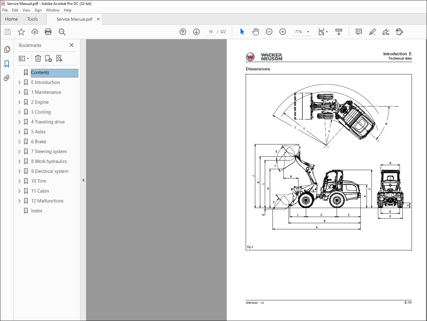
Dimensions E-11
E3 Tightening torques E-13
General tightening torques E-13
Specific tightening torques E-13
Torque values for metric coarse-pitch thread E-14
Torque values for metric fine-pitch thread E-15
Tightening torques for hydraulic screw connections and air-conditioning screw connections with
sealing cone and O-ring DIN 3865 E-16
Tightening torques for hydraulic screw connections with olive DIN 3861 E-17
Tightening torques for hydraulic system screw-in spud SDS E-18
Tightening torques for hydraulics rotating threaded fittings E-21
Tightening torques for banjo bolts DIN 7643 E-21
Tightening torques for adjustable hydraulics screw-in spuds SDE E-22
Tightening torques for brake line threaded fittings E-24
Tightening torques for worm drive hose clamps E-24
Tightening torques for spring-loaded worm drive hose clamps E-24
E4 Safety instructions E-25
Pay particular attention to the following E-25
Safety symbols and signal words E-25
Safety and Accident Prevention Regulations E-26
Safety instructions for repair work E-27
Safety instructions for work on the engine E-30
Safety instructions for work on the hydraulic system E-31
Safety instructions for work on the air conditioning system E-33
Safety instructions for work on traveling drive and axles E-33
Safety instructions for work on the braking system E-33
Safety instructions for work on the frame E-33
Safety instructions for work on the electrical system E-35
Safety instructions for work on the wheels E-35
E5 Special tools E-36
Claws and extractors E-36
Clamp E-36
I-2 SHB WL52 * 10 * [en]
I
B Operation
B1 Overview of control elements B-1
Control and display elements B-1
Indicating instruments B-3
Loader unit control lever B-4
Overview of rotary switches B-5
Overview of switch panels B-5
B2 Indicator lights and warning lights (overview) B-8
1 Maintenance
11 Information on maintenance 1-1
Responsibilities and prerequisites 1-1
Safety instructions 1-1
Battery master switch 1-5
12 Maintenance overview 1-6
Daily/weekly maintenance 1-6
Inspection schedules 1-7
Inspection intervals 1-10
13 Lubrication plan 1-13
14 Fluids and lubricants 1-15
Fluids and lubricants (overview) 1-15
Deutz engine TCD 29 L4 (554 kW) 1-16
15 Maintenance accesses 1-17
Maintenance openings 1-17
Raising the cabin sideways 1-18
16 Cleaning and maintenance 1-19
Information on cleaning and maintenance 1-19
Information on cleaning 1-20
General safety check 1-20
17 Lubrication work 1-21
Lubrication 1-21
Lubricating with the central lubrication system (option) 1-21
Central lubrication system diagram 1-24
Installing the high-pressure hoses on the central lubrication system 1-25
Instructions for troubleshooting in case of central lubrication system blocking 1-26
Repairing a blocking distributor of the central lubrication system 1-27
Troubleshooting table for central lubrication system 1-28
18 Fuel system 1-29
Information on the fuel system 1-29
Fuel system 1-30
Refueling with diesel fuel 1-30
Water separator maintenance 1-32
Replacing the fuel filter 1-33
Replace the fuel pre-filter 1-34
Bleeding the fuel system 1-35
19 Engine lubrication system 1-36
Replace the engine oil and engine oil filter 1-36
110 Cooling system 1-37
Information on the cooling system 1-37
Information on the coolant 1-37
Check / top off / replace the cooling liquid 1-38
Checking the antifreeze mixture 1-39
Cleaning the cooling system 1-40
SHB WL52 * 10 * [en] I-3
I
111 Air filter 1-42
Information on the engine air filter system 1-42
Engine air filter dust valve 1-43
Engine air filter 1-43
112 V-belt/toothed belt 1-45
Information on the V-belt 1-45
Checking the V-belt tension/tensioning the V-belt 1-46
Notes about tooth belts 1-47
113 Hydraulic system 1-48
Information on the hydraulic system 1-48
Replace the breather filter 1-49
Information on hydraulic oil 1-50
Checking the hydraulic oil level 1-50
Top off the hydraulic oil 1-51
Changing hydraulic oil 1-51
Replace the filter element of the hydraulic oil return filter 1-52
Replace the air cleaner (filter) element of the high pressure filter 1-52
Bleeding the hydraulic system 1-53
114 Electrical system 1-54
Information on the electrical system 1-54
Fuses 1-54
Information on the battery 1-55
Removing the battery 1-55
Battery maintenance 1-56
Starting aid and jump-starting 1-57
115 Heating, ventilation and air conditioning system (option) 1-59
Heating (option) maintenance 1-59
Maintenance of cabin breather filter 1-59
Maintenance of air conditioning (option) 1-59
116 Washer system 1-60
Filling up the washer system reservoir 1-60
117 Axles/traveling drive 1-61
Checking and replacing the axle oil 1-61
118 Braking system 1-63
Information on the braking system 1-63
119 Tires 1-64
Information on tires 1-64
Inflating the tires 1-65
Wheel change 1-66
Checking the liquid level of the tires 1-67
Ballasting wheels with liquid 1-67
120 Maintenance and servicing work on attachments 1-68
121 Maintenance of options 1-69
Automatic trailer coupling 1-69
122 Exhaust gas treatment 1-70
2 Engine
21 Complete component 2-1
Overview 2-1
Lube oil system 2-3
Exhaust gas recirculation 2-4
Exhaust-gas treatment 2-5
Electronic engine control unit 2-6
Removing/installing the engine 2-7
22 V-belt 2-12
V-belt of fan 2-12
V-belt of the alternator 2-12
23 Alternator 2-13
24 Removing/installing the starter 2-14
25 Removing/installing the air filter 2-16
26 Removing/installing the fuel tank 2-17
3 Cooling
31 Removing/installing the coolant reservoir 3-1
32 Removing/installing the radiator 3-2
33 Removing/installing fan blades 3-5
4 Traveling drive
41 Traveling drive hose routing 4-1
42 Variable displacement pump 4-2
Overview 4-2
Pressures 4-3
Checking/adjusting the pressure cutoff 4-4
Checking/adjusting the inching 4-5
Checking/adjusting the starting speed 4-5
Checking low pressure (supply pressure) 4-6
Checking the high pressure of the variable displacement pump 4-6
Checking the setting pressure of the variable displacement pump 4-7
Checking/adjusting the mechanical zero position 4-8
Removing/installing the variable displacement pump 4-10
43 Variable displacement motor 4-12
Overview 4-12
Checking and adjusting the control initiation of the variable displacement motor 4-13
Removing/installing the variable displacement motor 4-14
44 Hydraulic oil reservoir 4-16
Removing/installing the hydraulic oil reservoir 4-16
Removing/installing the return filter 4-17
Removing/installing the temperature switch 4-17
45 Removing/installing the cardan shaft 4-18
46 Troubleshooting 4-20
No forward or reverse travel 4-20
Machine travel starts too early 4-21
Machine travel starts too late 4-22
Severe engine droop 4-23
Not enough traction force 4-24
Travel speed is not reached 4-25
5 Axles
51 Front axle 5-1
Overview 5-1
Removing/installing the front axle 5-2
52 Rear axle 5-5
Overview 5-5
Removing/installing the rear axle 5-5
53 Type label – front/rear axle 5-9
6 Brake
61 Removing/installing the brake pedal 6-1
62 Removing/installing the parking brake 6-2
63 Removing/installing the parking brake Bowden cable 6-2
64 Master brake cylinder 6-3
Overview 6-3
Removing/installing the master brake cylinder 6-4
SHB WL52 * 10 * [en] I-5
I
7 Steering system
71 Hose routing 7-1
72 Removing/installing the steering wheel 7-2
73 Removing/installing the steering column 7-4
74 Removing/installing steering cylinder A81 7-5
75 Steering orbitrol S1 7-7
Overview 7-7
Removing/installing the steering orbitrol 7-8
8 Work hydraulics
81 Overview 8-1
82 Hose installation 8-2
Hoses of lift, tilt and lock cylinders 8-2
Hoses of lift and tilt cylinders with counterbalance valve 8-3
High Flow hose routing 8-4
Hose system of pulsation damper 8-5
Hose system of rear auxiliary control circuit with steering valve HDS21/1 8-6
Hose system of rear auxiliary control circuit with steering valve HDS21/2 8-7
83 Gear pump P45 8-8
Overview 8-8
Checking the gear pump 8-8
Removing/installing the gear pump 8-10
84 Removing/installing lock cylinder A4 8-11
85 Removing/installing the lock pin 8-12
86 Removing/installing the tilt cylinder 8-13
87 Removing/installing the loader unit 8-15
88 Removing/installing the lift cylinder 8-17
89 Removing/installing the reversing lever 8-19
810 Removing/installing solenoid valve V30 8-20
811 Removing/installing pressure relief valve V60 8-21
812 Removing/installing the quickhitch 8-23
813 Removing/installing the control valve 8-24
814 Designation of hydraulic components 8-26
815 Hydraulics diagram – HDS21/4 with HDS21/1 or 6/2 multiple way valve 8-28
816 Hydraulics diagram – HDS21/4 with HDS21/2 8-30
817 Hydraulics diagram – HDS21/3 with HDS21/1 or 6/2-multiple way valve 8-32
818 Hydraulics diagram – HDS21/3 with HDS21/2 8-34
819 Hydraulics diagram – HDS21/4 High Flow 8-36
9 Electrical system
91 Fuses 9-1
92 Fuse assignment 9-2
93 Removing/installing the machine control unit 9-5
Removal 9-5
Installation 9-5
94 Joystick 9-9
Overview 9-9
Removing/installing the joystick 9-10
95 Malfunctions of the machine electronics 9-11
96 Electrical diagram – Power supply (FG01-01) 9-12
97 Electrical diagram – ECU TTC77; Joystick lighting (FG01-02) 9-13
98 Electrical diagram – Deutz engine (FG02-01) 9-14
99 Electrical diagram – Deutz engine (FG02-02) 9-15
910 Electrical diagram – Deutz engine (FG02-03) 9-16
911 Electrical diagram – Bauser LED instrument (FG03-01) 9-17
912 Electrical diagram – Travel function (FG04-01) 9-18
913 Electrical diagram – StVZO (German road traffic regulations) lighting (FG05-01) 9-19
914 Electrical diagram – StVZO lighting (FG05-02) 9-20
915 Electrical diagram – Indicator system; Horn (FG06-01) 9-21
916 Electrical diagram – Window wiper / wash system (FG07-01) 9-22
917 Electrical diagram – Working lights; Rotating beacon (FG08-01) 9-23
918 Electrical diagram – Electrical connection; Tool lock; Continuous operation of 3rd control
circuit (FG09-01) 9-24
919 Electrical diagram – Hydraulic system (FG10-01) 9-25
920 Electrical diagram – Hydraulic system (FG10-02) 9-26
921 Electrical diagram – Hydraulic system (FG10-03) 9-27
922 Electrical diagram – Air conditioning; Seat (FG11-01) 9-28
923 Electrical diagram – Radio; Cigarette lighter; Interior lighting; Safe load indicator (FG12-01) 9-29
924 Designation of electrical components 9-30
Component list 9-30
Cable colours 9-37
10 Trim
101 Removing/installing the engine cover 10-1
102 Removing/installing the bottom plate 10-2
103 Removing/installing the trailer power outlet 10-3
104 Removing/installing the trailer coupling/chassis cover 10-4
105 Removing/installing the counterweight 10-6
11 Cabin
111 Removing/installing the operator seat 11-1
112 Removing/installing the indicating instrument 11-3
113 Removing/installing the starter 11-5
114 Removing/installing the tilt cylinder 11-6
115 Removing/installing the wiper motor 11-7
116 Heating 11-8
Removing/installing the heater fan 11-8
Removing/installing the heater box 11-9
117 Removing/installing the cabin 11-12
12 Malfunctions
121 Towing a machine 12-1
Preparations for towing 12-1
Towing the machine 12-2
After towing 12-2
122 Error code lists 12-3
Machine control unit TTC77 12-3
Motor controller Deutz TCD29
VIDEO PREVIEW OF THE MANUAL:
PLEASE NOTE:
- This is the same manual used by the dealers to diagnose and troubleshoot your vehicle
- You will be directed to the download page as soon as the purchase is completed. The whole payment and downloading process will take anywhere between 2-5 minutes
- Need any other service / repair / parts manual, please feel free to contact [email protected] . We still have 50,000 manuals unlisted
S.M