Wacker Neuson 1501 Dumper Service Manual – PDF DOWNLOAD
FILE DETAILS:
Wacker Neuson 1501 Dumper Service Manual – PDF DOWNLOAD
Language : English
Pages : 176
Downloadable : Yes
File Type : PDF
Size: 7.99 MB
VIDEO PREVIEW OF THE MANUAL:
DESCRIPTION:
Wacker Neuson 1501 Dumper Service Manual – PDF DOWNLOAD
Information on this service manual :
This service manual contains important information on how to service your machine safely, correctly and economically. Therefore, it aims not only at new operators, but it also serves as a reference for experienced ones. It helps to avoid hazardous situations and reduce repair costs and downtimes. Furthermore, the reliability and the service life of the machine will be increased by folllowing the instructions in the service manual.
IMAGES PREVIEW OF THE MANUAL:
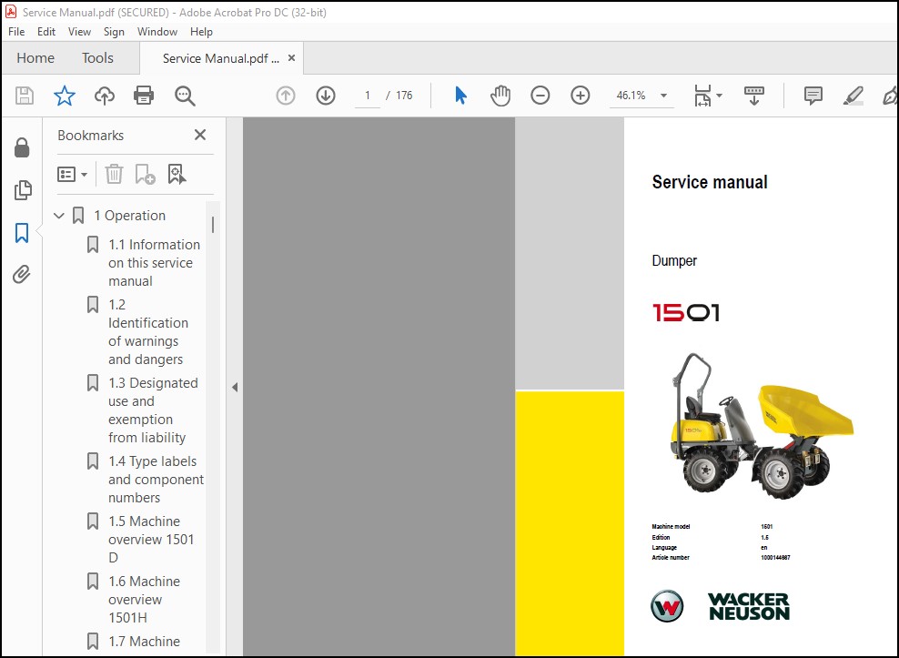
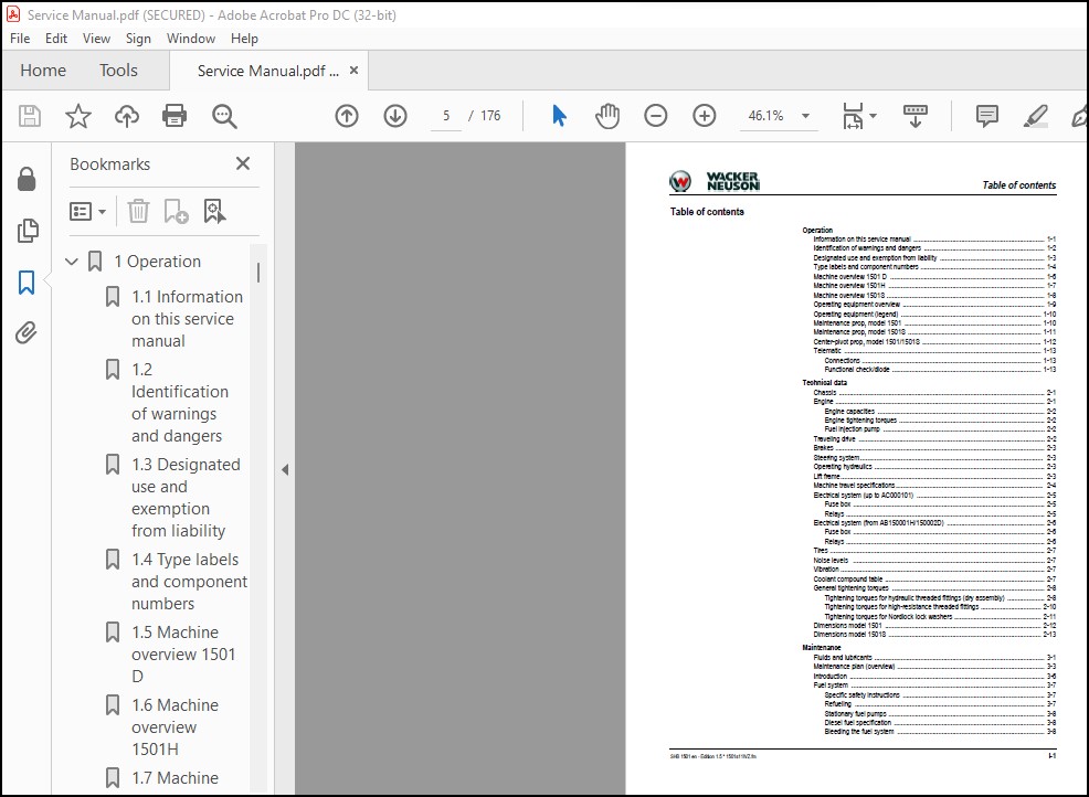

TABLE OF CONTENTS:
Wacker Neuson 1501 Dumper Service Manual – PDF DOWNLOAD
1 Operation……………………………………………………………………. 11
1.1 Information on this service manual………………………………………… 11
1.2 Identification of warnings and dangers…………………………………….. 12
1.3 Designated use and exemption from liability………………………………… 13
1.4 Type labels and component numbers…………………………………………. 14
1.5 Machine overview 1501 D………………………………………………….. 16
1.6 Machine overview 1501H…………………………………………………… 17
1.7 Machine overview 1501S…………………………………………………… 18
1.8 Operating equipment overview……………………………………………… 19
1.9 Operating equipment (legend)……………………………………………… 20
1.10 Maintenance prop, model 1501…………………………………………….. 20
1.11 Maintenance prop, model 1501S……………………………………………. 21
1.12 Center-pivot prop, model 1501/1501S………………………………………. 22
1.13 Telematic……………………………………………………………… 23
Connections…………………………………………………………….. 23
Functional check/diode…………………………………………………… 23
2 Technical data……………………………………………………………….. 27
2.1 Chassis………………………………………………………………… 27
2.2 Engine…………………………………………………………………. 27
Engine capacities……………………………………………………….. 28
Engine tightening torques………………………………………………… 28
Fuel injection pump……………………………………………………… 28
2.3 Traveling drive…………………………………………………………. 28
2.4 Brakes…………………………………………………………………. 29
2.5 Steering system…………………………………………………………. 29
2.6 Operating hydraulics…………………………………………………….. 29
2.7 Lift frame……………………………………………………………… 29
2.8 Machine travel specifications…………………………………………….. 30
2.9 Electrical system (up to AC000101)………………………………………… 31
Fuse box……………………………………………………………….. 31
Relays…………………………………………………………………. 31
2.10 Electrical system (from AB150001H/150002D)………………………………… 32
Fuse box……………………………………………………………….. 32
Relays…………………………………………………………………. 32
2.11 Tires…………………………………………………………………. 33
2.12 Noise levels…………………………………………………………… 33
2.13 Vibration……………………………………………………………… 33
2.14 Coolant compound table………………………………………………….. 33
2.15 General tightening torques………………………………………………. 34
Tightening torques for hydraulic threaded fittings (dry assembly)…………….. 34
Tightening torques for high-resistance threaded fittings…………………….. 36
Tightening torques for Nordlock lock washers……………………………….. 37
2.16 Dimensions model 1501…………………………………………………… 38
2.17 Dimensions model 1501S………………………………………………….. 39
3 Maintenance………………………………………………………………….. 43
3.1 Fluids and lubricants……………………………………………………. 43
3.2 Maintenance plan (overview)………………………………………………. 45
3.3 Introduction……………………………………………………………. 48
3.4 Fuel system…………………………………………………………….. 49
Specific safety instructions……………………………………………… 49
Refueling………………………………………………………………. 49
Stationary fuel pumps……………………………………………………. 50
Diesel fuel specification………………………………………………… 50
Bleeding the fuel system…………………………………………………. 50
Fuel prefilter with water separator……………………………………….. 51
Replacing the fuel filter………………………………………………… 52
3.5 Engine lubrication system………………………………………………… 53
Checking the oil level…………………………………………………… 53
Adding engine oil……………………………………………………….. 54
Changing engine oil……………………………………………………… 55
Replacing the engine-oil filter cartridge………………………………….. 56
3.6 Cooling system………………………………………………………….. 57
Specific safety instructions……………………………………………… 57
Checking the coolant level/adding coolant………………………………….. 58
Draining coolant………………………………………………………… 60
3.7 Air filter……………………………………………………………… 61
Weekly check of air filter for dirt……………………………………….. 61
Replacing the filter…………………………………………………….. 62
3.8 V-belt…………………………………………………………………. 63
Checking the V-belt tension………………………………………………. 63
Retensioning the V-belt………………………………………………….. 64
3.9 Hydraulic system………………………………………………………… 65
Specific safety instructions……………………………………………… 65
Checking the hydraulic oil level………………………………………….. 66
Adding hydraulic oil…………………………………………………….. 66
Changing hydraulic oil…………………………………………………… 67
Monitoring the hydraulic oil return filter…………………………………. 67
Replacing the hydraulic oil return filter………………………………….. 67
Checking hydraulic pressure lines…………………………………………. 68
3.10 Lubrication points 1501H (high-tip skip)………………………………….. 69
3.11 Lubrication points 1501S (swivel skip)……………………………………. 71
3.12 Tire maintenance……………………………………………………….. 73
Checks once a day……………………………………………………….. 73
Checks once a week………………………………………………………. 73
3.13 Changing wheels………………………………………………………… 74
Removing……………………………………………………………….. 74
Fitting………………………………………………………………… 74
3.14 Electrical system………………………………………………………. 75
Specific safety instructions……………………………………………… 75
Servicing and maintenance at regular intervals……………………………… 75
Instructions concerning specific components………………………………… 76
Alternator……………………………………………………………… 76
3.15 Battery……………………………………………………………….. 77
Battery charge condition…………………………………………………. 77
Charging the battery…………………………………………………….. 77
Replacing the battery……………………………………………………. 77
3.16 Battery master switch…………………………………………………… 78
3.17 General maintenance…………………………………………………….. 79
Cleaning……………………………………………………………….. 79
General instructions for all areas of the machine…………………………… 79
Threaded fittings and attachments…………………………………………. 79
Pivots and hinges……………………………………………………….. 79
4 Engine………………………………………………………………………. 83
4.1 Engine overview 3TNE74 (up to AC000335)……………………………………. 83
4.2 Fuel system (up to AC000335)……………………………………………… 85
4.3 Engine overview 3TNV76 – XNSV (from AB150001H/AB150002D)…………………….. 86
4.4 Fuel system (from AB150001H/AB150002D)…………………………………….. 88
4.5 Checking and adjusting valve clearance…………………………………….. 89
4.6 Tightening order for cylinder head bolts…………………………………… 90
4.7 Checking the injection nozzles……………………………………………. 91
Pressure check………………………………………………………….. 91
4.8 Checking the nozzle jet………………………………………………….. 91
4.9 Fuel injection time (up to AC000335)………………………………………. 92
4.10 Fuel injection time (from AB150001H/AB150002D)…………………………….. 93
4.11 Adjusting engine speed………………………………………………….. 94
4.12 Compression……………………………………………………………. 94
4.13 Checking the coolant thermostat………………………………………….. 94
4.14 Checking the thermal switch……………………………………………… 95
4.15 Oil pressure switch…………………………………………………….. 95
4.16 Checking the coolant circuit…………………………………………….. 96
4.17 Engine malfunctions…………………………………………………….. 96
5 Traveling drive……………………………………………………………….101
5.1 Variable displacement pump A10VG45DA……………………………………….101
Variable displacement pump: diagram………………………………………..103
Variable displacement pump: diagram………………………………………..104
Power train overview……………………………………………………..105
Connecting plate with valves………………………………………………106
5.2 Rear traveling drive (up to serial no. WNCD0105KPAL00316)…………………….107
5.3 Front traveling drive (up to serial no. WNCD0105KPAL00316)……………………108
Hydraulic motor (exploded view)……………………………………………109
5.4 Traveling drive overview………………………………………………….111
5.5 Towing and transporting the machine………………………………………..112
Safety instructions………………………………………………………112
Towing………………………………………………………………….112
Opening the high-pressure circuit………………………………………….112
Releasing the hydraulic parking brake………………………………………113
5.6 Test instructions………………………………………………………..114
Control pressure check……………………………………………………114
High pressure check………………………………………………………115
5.7 Traveling drive (from serial no. WNCD0105JPAL00317)………………………….116
Front traveling drive…………………………………………………….116
Rear traveling drive……………………………………………………..116
6 Brakes……………………………………………………………………….119
6.1 Brake circuit up to serial no. AC000241…………………………………….119
Brake diagram……………………………………………………………120
6.2 Brake circuit from serial no. AC000242……………………………………..121
Brake diagram……………………………………………………………122
7 Steering system……………………………………………………………….125
7.1 Steering circuit…………………………………………………………125
7.2 Steering unit: diagram……………………………………………………126
Function………………………………………………………………..126
7.3 Steering unit connections…………………………………………………127
7.4 Steering unit overview……………………………………………………128
Priority valve overview…………………………………………………..128
Priority valve (legend)…………………………………………………..128
Steering gear overview……………………………………………………129
Steering unit (legend)……………………………………………………130
8 Hydraulic system………………………………………………………………133
8.1 Control valve connections (overview)……………………………………….133
8.2 Test instructions………………………………………………………..134
Check: work pump pressure…………………………………………………134
8.3 1501 diagram up to serial no. AC000241……………………………………..135
8.4 1501 diagram up to serial no. AC000241 (legend)……………………………..136
8.5 1501 diagram from AB150001H/AB150002D………………………………………137
8.6 1501 diagram from AB150001H/AB150002D (legend)………………………………138
8.7 1501S diagram up to serial no. AC000241…………………………………….139
8.8 Diagram 1501S (legend)……………………………………………………140
8.9 1501S diagram up to serial no. AC000242…………………………………….141
8.10 1501S diagram from serial no. AC000242 (legend)…………………………….142
8.11 Hydraulics diagram 1501 (up to serial no. AC000241)………………………… 0
8.12 Hydraulics diagram 1501 (from serial no. AB150001H/AB150002D)……………….. 0
8.13 Hydraulics diagram 1501S (up to serial no. AC000241)……………………….. 0
8.14 Hydraulics diagram 1501S (from serial no. AC000242)………………………… 0
9 Electrical system……………………………………………………………..149
9.1 Ohm’s Law (current, voltage, resistance); power……………………………..149
9.2 Measuring equipment, measuring methods……………………………………..149
9.3 Relays………………………………………………………………….150
Use, mode of function…………………………………………………….150
9.4 Electric units…………………………………………………………..151
9.5 Fuse box in instrument panel (up to AC000335)……………………………….151
Relays………………………………………………………………….151
9.6 Instrument panel overview…………………………………………………152
9.7 Fuse box on instrument panel (from AB150001H/AB150001D)………………………153
Relays………………………………………………………………….153
9.8 Instrument panel overview (from AB150001H/AB150001D)…………………………154
9.9 Main wiring harness legend………………………………………………..156
9.10 Main wiring harness……………………………………………………..157
9.11 Main wiring harness legend……………………………………………….158
9.12 Main wiring harness……………………………………………………..159
9.13 Engine wiring harness from AB150001H/AB150002D (legend)……………………..160
9.14 Engine wiring harness from AB150001H/AB150002D……………………………..161
9.15 Rotating beacon wiring harness……………………………………………162
9.16 Battery lead……………………………………………………………163
9.17 Trailer socket wiring harness…………………………………………….164
9.18 Wiring diagram legend (up to serial no. AC000241)………………………….. 0
9.19 Wiring diagram (up to serial no. AC000241)………………………………… 0
9.20 Wiring diagram legend (serial no. AC000242 to AC000335)…………………….. 0
9.18 Wiring diagram (serial no. AC000242 to AC000335)…………………………… 0
9.19 Wiring diagram legend (serial no. AB150001H / AB150002D to WNCD0105HPAL00275)…. 0
9.20 Wiring diagram (serial no. AB150001H / AB150002D to WNCD0105HPAL00275)……….. 0
9.21 Wiring diagram legend (from serial no. WNCD0105EPAL00276)…………………… 0
9.22 Wiring diagram (from serial no. WNCD0105EPAL00276)…………………………. 0
PLEASE NOTE:
- This is the SAME exact manual used by your dealers to fix your vehicle.
- The same can be yours in the next 2-3 mins as you will be directed to the download page immediately after paying for the manual.
- Any queries / doubts regarding your purchase, please feel free to contact [email protected]
S.V