

Volvo FL10 FL12 AWD Wiring Diagram Manual – PDF DOWNLOAD
DESCRIPTION:
Volvo FL10 FL12 AWD Wiring Diagram Manual – PDF DOWNLOAD
Foreword :
- The descriptions and service procedures contained in this manual are based on designs and
methods studies carried out up to March 1995. - The products are under continuous development. Vehicles and components produced after
the above date may therefore have different specifications and repair methods. When this is
judged to have a significant bearing on this manual, supplementary service bulletins will be
issued to cover the changes. - The new edition of this manual will update the changes.
- In service procedures where the title incorporates an operation number, this is a reference to
V.S.T. (Volvo Standard Times). - Service procedures which do not include an operation number in the title are for general
information and no reference is made to V.S.T.
The following levels of observations, cautions and warnings are used in this Service
Documentation:
Note: Indicates a procedure, practice, or condition that must be followed in order to have the
vehicle or component function in the manner intended.
Caution: Indicates an unsafe practice where damage to the product could occur.
Warning: Indicates an unsafe practice where personal injury or severe damage to the product
could occur.
Danger: Indicates an unsafe practice where serious personal injury or death could occur.
TABLE OF CONTENTS:
Volvo FL10 FL12 AWD Wiring Diagram Manual – PDF DOWNLOAD
Component wiring diagram index ………………………………………………. 2
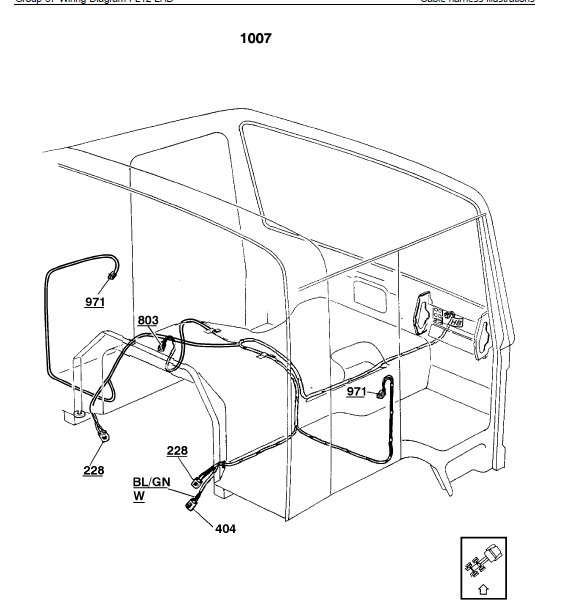
Cable harness illustration index …………………………………………………. 5
Circuit board (32) electrical centre ……………………………………………… 8
Fuses on circuit board (32) electrical centre …………………………….. 10
Relays on circuit board (32) electrical centre ……………………………. 10
6–unit fuse holder …………………………………………………………………….. 11
List of connectors ……………………………………………………………………. 12
List of components ………………………………………………………………….. 17
Abbreviations …………………………………………………………………………… 22
Cable colour code ……………………………………………………………………. 22
Cable harness illustrations ……………………………………………………….. 23
Component wiring diagrams …………………………………………………….. 73
Feedback
Foldout A Wiring diagram BL
Foldout B Wiring diagram CE
Foldout C Wiring diagram GA
Foldout D Wiring diagram HA
Foldout E Wiring diagram HC
Foldout F Wiring diagram LO
Foldout G Wiring diagram LP
Foldout H Wiring diagram MD
Foldout I Wiring diagram MN
Foldout J Wiring diagram MR
Foldout K Wiring diagram NA
Foldout L Wiring diagram ND
Foldout M Wiring diagram NG
Foldout N Wiring diagram OA
Foldout O Wiring diagram XD
Foldout P Wiring diagram ZA
Foldout Q Wiring diagram ZD
IMAGES PREVIEW OF THE MANUAL:
PLEASE NOTE:
- This is the same manual used by the dealers to diagnose and troubleshoot your vehicle
- You will be directed to the download page as soon as the purchase is completed. The whole payment and downloading process will take anywhere between 2-5 minutes
- Need any other service / repair / parts manual, please feel free to contact [email protected] . We still have 50,000 manuals unlisted
S.V


