

Toyota 8HBW30 8HBE40 8HBC40 8HBE30 8HBC30 8TB50 Pallet Trucks Service Manual 00700-CL398-07 – PDF DOWNLOAD
FILE DETAILS:
Toyota 8HBW30 8HBE40 8HBC40 8HBE30 8HBC30 8TB50 Pallet Trucks Service Manual 00700-CL398-07 – PDF DOWNLOAD
Language : English
Pages : 258
Downloadable : Yes
File Type : PDF
DESCRIPTION:
Toyota 8HBW30 8HBE40 8HBC40 8HBE30 8HBC30 8TB50 Pallet Trucks Service Manual 00700-CL398-07 – PDF DOWNLOAD
8HBW30 36,001 and up 8HBE30 36,001 and up
8HBE40 36,001 and up 8HBC30 36,001 and up
8HBC40 36,001 and up 8TB50 36,001 and up
Manual Design:
The Toyota Pallet Truck Service Manual is designed with the following objectives in mind:
- Provide technical coverage for expected levels of user expertise
- Anticipate your needs and reduce your decisions regarding maintenance
- Reduce page flipping through a “one-stop shopping” approach
The two-line running page header at the top of each page tells you:
- Name of the manual
(Toyota Pallet Truck Service Manual) - Current Chapter Title
(for example, this page How to Use This Manual) - Current topic
(for example, this page Manual Design)
We suggest you get in the habit of turning to the START page first when you use this manual.
• The START page asks a few questions to guide you to the correct section.
- How to Use This Manual explains the manual format and design and contains the Table of Contents and START page.
- Safety explains warning and caution notes, general safety rules and safety rules for batteries, static, jacking, and welding.
- Systems Overview includes truck specifications and theory of operation information.
- Planned Maintenance outlines the recommended schedule of preventive services to keep your truck working most efficiently.
- Troubleshooting is a set of “decision-tree” charts and tables designed to take you from a symptom to a specific sequence of tests in order to isolate a failing component.
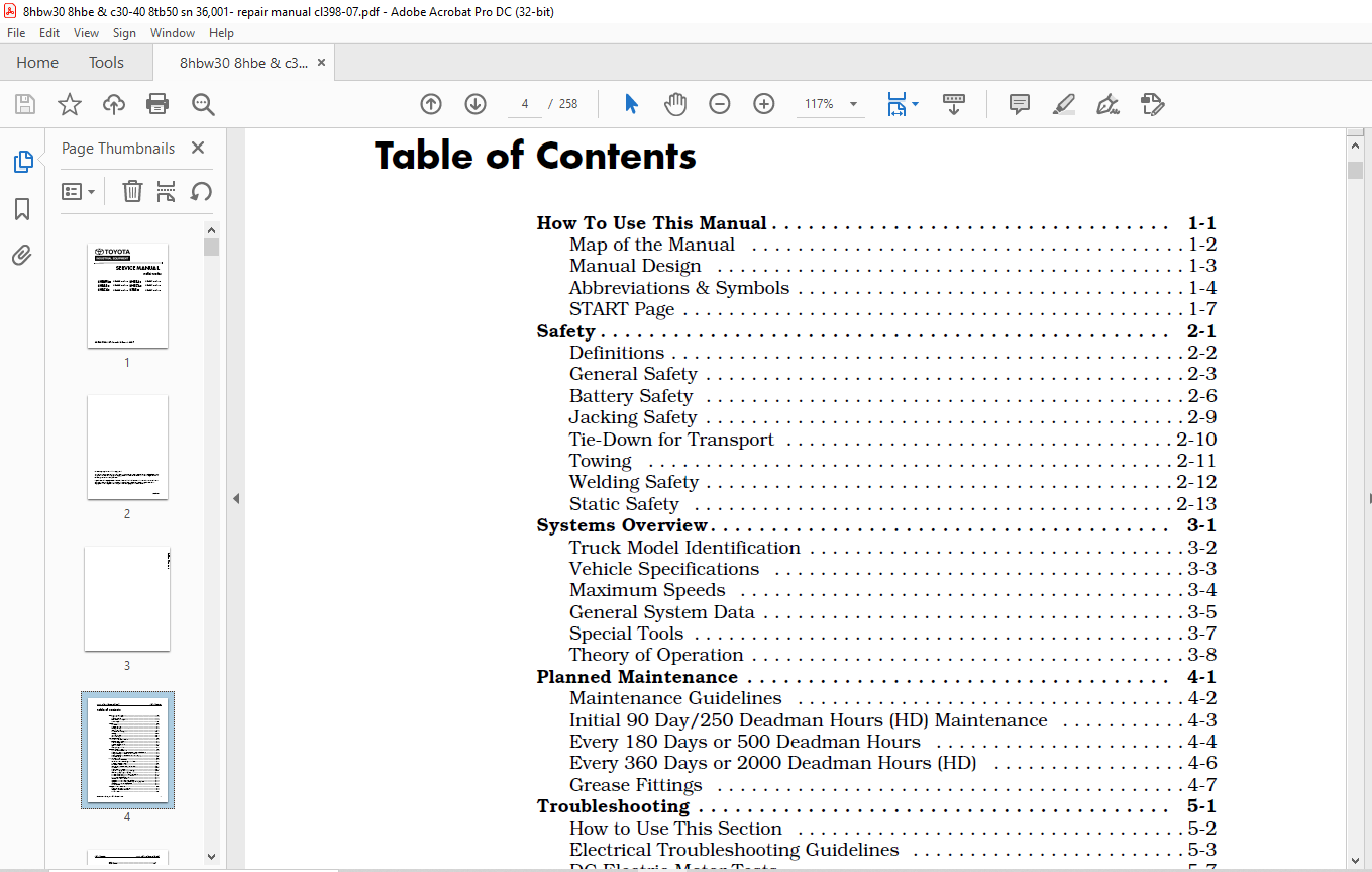
TABLE OF CONTENTS:
Toyota 8HBW30 8HBE40 8HBC40 8HBE30 8HBC30 8TB50 Pallet Trucks Service Manual 00700-CL398-07 – PDF DOWNLOAD
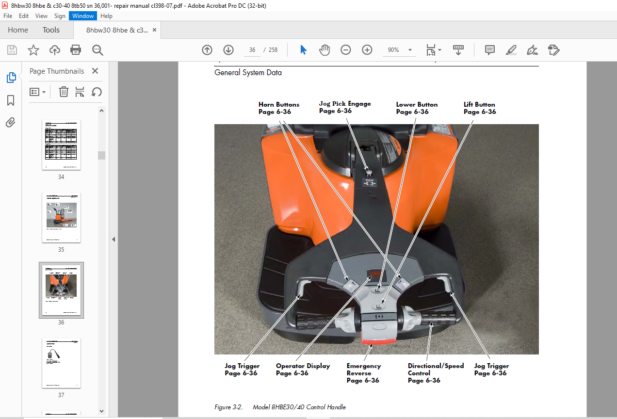
Front Cover.................................................................................................  1
Table of Contents...........................................................................................  4
Section 1. How To Use This Manual ..........................................................................  7
	Map of the Manual ......................................................................................  8
	Manual Design ..........................................................................................  9
	Abbreviations & Symbols ................................................................................ 10
	START Page ............................................................................................. 13
Section 2. Safety .......................................................................................... 16
	Definitions ............................................................................................ 17
	General Safety ......................................................................................... 18
	Battery Safety ......................................................................................... 21
	Jacking Safety ......................................................................................... 24
	Tie-Down for Transport ................................................................................. 25
		Figure 2-1. Tie-Down for Transport ................................................................. 25
	Towing ................................................................................................. 26
	Welding Safety ......................................................................................... 27
	Static Safety .......................................................................................... 28
		Figure 2-2. Anti-Static Kit (P/N 00590-04849-71) With Wrist Strap and Mat .......................... 28
Section 3. Systems Overview ................................................................................ 31
	Truck Model Identification ............................................................................. 32
	Vehicle Specifications ................................................................................. 33
	Maximum Speeds ......................................................................................... 34
		Tractor First ...................................................................................... 34
		Forks First ........................................................................................ 34
	General System Data .................................................................................... 35
		Figure 3-1. Model 8HBE30/40 (Long-John Forks Shown) ................................................ 35
		Figure 3-2. Model 8HBE30/40 Control Handle ......................................................... 36
	Special Tools .......................................................................................... 37
		Service Key ........................................................................................ 37
			Figure 3-3. Service Key ........................................................................ 37
	Theory of Operation .................................................................................... 38
		Vehicle Manager (VM) ............................................................................... 38
		Traction Power Amplifier (TPA) ..................................................................... 38
		Traction System .................................................................................... 38
		Emergency Reverse (Model 8HBW30 and 8HBE30/40) ..................................................... 39
		Strip Curtain Bypass (Model 8HBE30/40 only) ........................................................ 39
		Lift/Lower System .................................................................................. 40
		Jog Pick Mode ...................................................................................... 40
		Model 8HBE30/40 only ............................................................................... 41
		Manual Jog Pick .................................................................................... 41
Section 4. Planned Maintenance ............................................................................. 44
	Maintenance Guidelines ................................................................................. 45
	Initial 90 Day/250 Deadman Hours (HD) Maintenance ...................................................... 46
	Every 180 Days or 500 Deadman Hours .................................................................... 47
	Every 360 Days or 2000 Deadman Hours (HD) .............................................................. 49
	Grease Fittings ........................................................................................ 50
		Figure 4-1. Caster Grease Fittings ................................................................. 50
		Figure 4-2. Upper Bell Crank Grease Fittings (Between Tractor and Fork Section) .................... 50
		Figure 4-3. Lower Bell Crank Grease Fittings-left side shown (Between Tractor and Fork Section) .... 50
		Figure 4-4. Load Wheel Grease Fittings and Fork Grease Fittings (Top View-8K trucks) ............... 51
Section 5. Troubleshooting ................................................................................. 53
	How to Use This Section ................................................................................ 54
	Electrical Troubleshooting Guidelines .................................................................. 55
		Troubleshooting the CAN Bus ........................................................................ 55
		Checking for Shorts from Battery to Truck Frame .................................................... 57
		Checking for Shorts from Components to Truck Frame ................................................. 58
	DC Electric Motor Tests ................................................................................ 59
		DC Motor Types ..................................................................................... 59
			Figure 5-1. Motor Circuits ..................................................................... 59
		Open Circuit Motor Test ............................................................................ 59
		Grounded Motor Test ................................................................................ 59
		Short-Circuited Winding ............................................................................ 60
		Short-Circuited Armature ........................................................................... 60
	AC Electric Motor Tests ................................................................................ 61
		Figure 5-2. AC Traction Motor circuits ............................................................. 61
		AC Motor Type ...................................................................................... 61
		Open Winding ....................................................................................... 61
		Shorted Winding .................................................................................... 61
	Hydraulic Troubleshooting Guidelines ................................................................... 62
	Definitions ............................................................................................ 63
		Figure 5-3. Brake (Deadman) Switch and Brake Actuation ............................................. 63
	List of Electrical Symbols ............................................................................. 67
	Operator Display and Programming ....................................................................... 69
		Figure 5-4. Operator Display ....................................................................... 69
		Special Truck Mode ................................................................................. 69
		Hour Meter (H) ..................................................................................... 69
		Error Codes (E) .................................................................................... 69
		Changing Truck Parameters (P) ...................................................................... 70
	Service Input/Output Displays .......................................................................... 75
		Figure 5-5. Service Key Connection Point ........................................................... 75
		Figure 5-6. Operator Display ....................................................................... 75
		Digital Inputs/Outputs from Traction Power Amplifier and VM ........................................ 76
	Traction Power Amplifier LED Diagnostics ............................................................... 78
		Figure 5-7. Traction Power Amplifier Status Indicator LED .......................................... 78
	Traction Power Amplifier Flash Codes ................................................................... 79
	Troubleshooting Flowcharts ............................................................................. 81
	Caution and Error Codes ................................................................................ 85
		Figure 5-8: Operator Display ....................................................................... 85
		Caution Codes ...................................................................................... 85
		Error Codes ........................................................................................ 97
	Symptom Tables: Lift/Lower System ......................................................................107
	Symptom Tables: Travel (Forward/Reverse) System ........................................................111
	Symptom Tables: Wiring System ..........................................................................120
	Pinout Matrix ..........................................................................................121
Section 6. Component Procedures ............................................................................136
	List of Component Procedures ...........................................................................137
	Component Locator Photos ...............................................................................140
		Figure 6-1. Inside Tractor, Rear View ..............................................................140
		Figure 6-2. Inside Tractor, Right Side .............................................................141
	Tractor Cover ..........................................................................................142
		Figure 6-3. Cover Handle Hold Locations ............................................................142
	Battery ................................................................................................143
		With Battery Gates and Rollers (Optional) ..........................................................143
		Battery Gates (Optional) ...........................................................................143
		Battery Rollers (Optional) .........................................................................143
		Without Battery Gates and Rollers ..................................................................143
		Battery Exterior Cleaning ..........................................................................144
			Figure 6-4. Battery Filler Plugs and Vent Holes ................................................144
		Testing, Charging, and Maintenance .................................................................145
		Maintenance-Free Batteries .........................................................................145
		Storage ............................................................................................145
	Power Cables ...........................................................................................146
	Wiring Harness .........................................................................................147
	Fuses ..................................................................................................149
		Figure 6-5. Fuse Location ..........................................................................149
	Switches (General) .....................................................................................150
	Key Switch (SW1) .......................................................................................151
		Figure 6-6. Key Switch Location ....................................................................151
	Brake (Deadman) Switch (SW2) ...........................................................................152
		Figure 6-7. Brake (Deadman) Switch, 8HBW30 and 8HBE30 or 8HBE40 ....................................152
		Figure 6-8. Brake (Deadman) Switch Active, 8HBW30 and 8HBE30 or 8HBE40 .............................152
	Lift-Limit Switch (SW8) ................................................................................154
		Figure 6-9. Lift-Limit Switch ......................................................................154
	Grab Rail Switches .....................................................................................155
		Model 8HBE30/40 Only ...............................................................................155
			Figure 6-10. Grab Rail Switch Removal, Left Side ...............................................155
			Figure 6-11: Grab Rail Switch Removal, Right Side ..............................................155
	Hydraulic Solenoids ....................................................................................156
		Figure 6-12. Hydraulic Solenoids (typical unit) ....................................................156
	Jog Pick Solenoid ......................................................................................157
		Model 8HBE30/40 (Optional) .........................................................................157
			Figure 6-13. Socket Head Cap Screws ............................................................157
			Figure 6-14. Removed Solenoid Mechanism ........................................................157
		Jog Pick Solenoid Switch ...........................................................................157
		Canister ...........................................................................................158
			Figure 6-15. Canister Spacing ..................................................................158
	Horn ...................................................................................................159
		Figure 6-16. Horn Location .........................................................................159
	Traction Power Amplifier ...............................................................................160
		Figure 6-17. Traction Power Amplifier Location .....................................................160
		Figure 6-18. Removing the Traction Power Amplifier .................................................160
	AMP Harness/Traction Power Amplifier Connector .........................................................162
		Connector Components ...............................................................................162
			Figure 6-19. JP1 Connector Components ..........................................................162
			Figure 6-20. AMP JP1 Connector .................................................................162
			Figure 6-21. Contact Insertion .................................................................163
			Figure 6-22. Wedge Lock Latches ................................................................163
			Figure 6-23. Wedge Lock Flush With Housing .....................................................164
	Contactors .............................................................................................165
		Figure 6-24. Disconnecting Main Contactor ..........................................................165
		Main Contactor .....................................................................................165
			Figure 6-25. Removing Top Cover ................................................................165
			Figure 6-26. Removing Brass Lock Nuts ..........................................................166
			Figure 6-27. Removing the Fixed Contacts .......................................................166
			Figure 6-28. Installing Fixed Contacts .........................................................166
			Figure 6-29. Main Contactor Components .........................................................166
			Figure 6-30. Installing the Main Contactor .....................................................167
	Control Handle Assembly ................................................................................168
		Spring-Loaded Handle Design - Models 8HBW30 and 8HBE30 or 8HBE40 ...................................168
			Figure 6-31. Control Handle Base Cover Removal .................................................168
			Figure 6-32. Control Handle Wire Harness .......................................................168
			Figure 6-33. Remove Jam Nut at Coast Link ......................................................168
			Figure 6-34: Return Spring Rod Removal .........................................................169
		Return Spring Adjustment ...........................................................................169
			Figure 6-35. Return Spring Adjustment ..........................................................169
		Fixed-Position Handle Design - Models 8HBC30/40 and 8TB50 ..........................................170
	Control Handle .........................................................................................171
		Figure 6-36. Handle and Control Head Assembly ......................................................171
		Figure 6-37. Control Head Assembly -Exploded View ..................................................172
		Control Head Removal ...............................................................................173
			Figure 6-38. Horn Button Removal ...............................................................174
			Figure 6-39. Lift/Lower Button Removal .........................................................174
			Figure 6-40. Push Button Removal ...............................................................174
			Figure 6-41. Handle with Jog Pick Option .......................................................175
	Brake ..................................................................................................176
		Spring-Loaded Handle - Models 8HBW30 and 8HBE30 or 8HBE40 ..........................................176
			Figure 6-42. Brake Adjustment, location ........................................................176
			Figure 6-43: Brake Adjusting Screw .............................................................176
			Figure 6-44. Brake Drum With Control Handle and Brake Shield Removed ...........................177
			Figure 6-45. Brake Adjusting Screw .............................................................177
			Figure 6-46. Brake Adjusting Rod (Installed) ...................................................177
		Fixed-Position Handle - Models 8HBC30/40 and 8TB50 .................................................178
	Motors, General ........................................................................................180
		Terminal Nuts ......................................................................................180
			Figure 6-47. Traction Motor Terminal Connections ...............................................180
			Figure 6-48. Lift and Aux Motor Terminal Nuts ..................................................180
	Traction Motor .........................................................................................181
		Figure 6-49. Control Handle Base Cover Removal .....................................................181
		Figure 6-50. Control Handle Mounting Frame Removal .................................................181
		Figure 6-51. Traction Motor Power Cables ...........................................................181
		Figure 6-52. Traction Motor Removal ................................................................182
		Figure 6-53. Drive Unit Pinion Gear ................................................................182
		Figure 6-54. Main Case Location ....................................................................182
		Figure 6-55. Traction Motor Installation ...........................................................183
	AC Motor Service .......................................................................................184
		AC Motor Temperature Sensor ........................................................................184
	Drive Unit .............................................................................................186
		Figure 6-56. Drive Unit Fill Plug ..................................................................186
		Figure 6-57. Drive Unit Drain Plug .................................................................186
		Figure 6-58. Drive Unit Mounting (Traction Motor Removed) ..........................................186
		Steering Bearing ...................................................................................187
			Figure 6-59. Drive Unit (Shown installed in Tractor Frame) .....................................187
			Figure 6-60. Drive Unit Bottom View ............................................................187
			Figure 6-61. Drive Unit, Steering Bearing Removed ..............................................187
			Figure 6-62. Steering Bearing Locating Groove ..................................................187
			Figure 6-63. Main Case Cover, Six Hole-Type, Installed .........................................188
			Figure 6-64. Gear Housing and Cover ............................................................188
			Figure 6-65. Lower Drive Unit, Cross-Sectional View, Model 8HBW30 and 8HBE30 or 8HBE40 .........189
		Gear Assembly ......................................................................................190
		Checking the Gears .................................................................................191
			Figure 6-66. Drive Unit Gear Tooth Pattern .....................................................191
			Figure 6-67. Drive Unit Mounting Location in Frame .............................................192
			Figure 6-68. Drive Unit Installed In Frame .....................................................192
			Figure 6-69. Drive Unit Shimming Locations .....................................................192
			Figure 6-70. Drive Unit Drain Plug .............................................................193
		Drive Housing Lubrication ..........................................................................193
			Figure 6-71. Drive Unit Fill Level Dipstick ....................................................193
			Figure 6-72. Drive Unit Drain Plug .............................................................193
	Drive Wheel ............................................................................................195
		Figure 6-73. Drive Wheel and Tire ..................................................................195
		Figure 6-74. Cushion Tire Replacement ..............................................................195
	Casters (Torsion) ......................................................................................198
		Figure 6-75. Removing Caster Wheel Assembly ........................................................198
		Caster Removal .....................................................................................198
			Figure 6-76. Caster Assembly, Disassembled .....................................................198
		Wheel Replacement ..................................................................................198
			Figure 6-77. Caster Assembly, Assembled ........................................................199
		Caster Assembly ....................................................................................199
		Caster Installation ................................................................................199
			Figure 6-78. Securing Caster To Tractor ........................................................199
	Casters (Spring-Loaded) ................................................................................200
		Figure 6-79. Removing Spring-Loaded Caster .........................................................200
		Removal ............................................................................................200
		Wheel Replacement ..................................................................................200
			Figure 6-80. Removing Axle Shaft ...............................................................200
			Figure 6-81. Removing Tension Pin ..............................................................200
			Figure 6-82. Removed Wheel and Shims ...........................................................201
			Figure 6-83. Compressing Caster Springs ........................................................201
		Caster Disassembly .................................................................................201
			Figure 6-84. Relieving Pivot Tension ...........................................................201
			Figure 6-85. Removing Pivot Pin Retainer Screw .................................................201
			Figure 6-86. Removing Pivot Pin ................................................................202
			Figure 6-87. Separated Caster ..................................................................202
		Caster Assembly ....................................................................................202
			Figure 6-88. Removing Bolts from Springs .......................................................202
			Figure 6-89. Installing New Wheel ..............................................................202
		Wheel Installation .................................................................................203
			Figure 6-90. Installing Axle Shaft .............................................................203
			Figure 6-91. Installing Tension Pin ............................................................203
			Figure 6-92. Caster, Shims and Mounting Bolts ..................................................203
		Caster Installation ................................................................................203
			Figure 6-93. Securing Caster To Tractor ........................................................203
	Load Wheels ............................................................................................204
		Figure 6-94. Removing Tension Pin ..................................................................204
		Models 8HBW30, 8HBE30/40 and 8HBC30/40 .............................................................204
			Figure 6-95. Removing Axle From Load Arm Casting ...............................................204
			Figure 6-96. Removed Load Wheel and Components .................................................204
		Model 8TB50 ........................................................................................205
			Figure 6-97. Model 8TB50 Load Wheel Suspension-Exploded View ...................................205
		Load Wheel Suspension (Optional) ...................................................................206
			Figure 6-98. Model 8TB50 Optional Load Wheel Suspension-Exploded View ..........................206
	Pallet Entry Sliders ...................................................................................207
		Figure 6-99. Replacing Pallet Entry Slider (6000 lb. Standard Model Shown) .........................207
	Fork Height Adjustment .................................................................................208
		Figure 6-100. Fork Height Adjustment at Lower Bell Crank ...........................................208
		Measurement ........................................................................................208
		Adjustment .........................................................................................208
	Hydraulic Components ...................................................................................210
		General Guidelines .................................................................................210
			Figure 6-101. Hydraulic Unit (typical shown) ...................................................210
	Hydraulic Fluid ........................................................................................211
		Figure 6-102. Hydraulic Connections ................................................................211
	Adjusting Hydraulic Pump Relief Valve Pressure .........................................................212
		Figure 6-103. Checking Relief Valve Pressure .......................................................212
		Relief Valve Settings ..............................................................................212
		Check Valve ........................................................................................213
	Hydraulic Ram ..........................................................................................214
		Figure 6-104. Blocking Fork Section For Ram Removal ................................................214
		Figure 6-105. Removing Lower Bell Crank Pins .......................................................214
		Figure 6-106. Disconnecting Upper Clevis Brackets ..................................................215
		Figure 6-107. Hydraulic Ram Area, Forks Removed ....................................................215
		Figure 6-108. Hydraulic Line Connection ............................................................215
		Figure 6-109. Vent Hose Connections ................................................................215
		Figure 6-110. Hydraulic Ram Removal/Installation ...................................................216
		Figure 6-111. Hydraulic Line Connection (installed) ................................................216
		Hydraulic Cylinder Seals ...........................................................................217
			Figure 6-112. Remove Outer Spiral Lock Ring ....................................................217
			Figure 6-113. Remove the Spacer ................................................................217
			Figure 6-114. Remove Head Lock Ring From Cylinder ..............................................217
			Figure 6-115. Rod and Head Assembly Out of Cylinder ............................................218
			Figure 6-116. Remove the Piston Jam Nut ........................................................218
			Figure 6-117. Piston Rod Components ............................................................218
			Figure 6-118. Securing Piston Jam Nut ..........................................................218
			Figure 6-119. Installing the Head Lock Ring ....................................................219
			Figure 6-120. Installing the Outer Lock Ring ...................................................219
	Hydraulic Unit .........................................................................................220
		Figure 6-121. Hydraulic Unit (typical shown) .......................................................220
		Hydraulic Reservoir ................................................................................221
			Figure 6-122. Adapter Cap Screws ...............................................................221
			Figure 6-123. Removed Reservoir ................................................................221
			Figure 6-124. Pump Housing Components ..........................................................221
		Filter Screen and Suction Tube .....................................................................222
			Figure 6-125. Cleaning Filter Screen ...........................................................222
			Figure 6-126. Pump and Adapter Body ............................................................222
		Hydraulic Pump .....................................................................................222
			Figure 6-127. Pump Drive Coupling ..............................................................222
			Figure 6-128. Installing Pump In Adapter .......................................................223
	Lift Motor .............................................................................................224
		General Data .......................................................................................224
			Figure 6-129. Bolts Securing Motor To Adapter ..................................................224
			Figure 6-130. Separated Reservoir and Motor (typical) ..........................................224
			Figure 6-131. Coupling Cavity ..................................................................225
			Figure 6-132. Indexing Pin .....................................................................225
	Cold Storage Conditioning ..............................................................................226
Section A. Appendix ........................................................................................229
	Lubrication Equivalency Chart ..........................................................................230
	Torque Chart - Standard (Ferrous) ......................................................................231
	Torque Chart - Standard (Brass) ........................................................................232
	Torque Chart - Metric ..................................................................................233
	Torque Chart - Thread-Forming Screws ...................................................................234
	Decimal Equivalent Chart ...............................................................................235
	Standard/Metric Conversions ............................................................................237
	Electrical Schematics ..................................................................................240
		Figure B-1. Model 8HBW30 Electrical Schematic (Sheet 1 of 2) .......................................241
		Figure B-2. Model 8HBE30/40 End Rider Electrical Schematic (Sheet 1 of 2) ..........................243
		Figure B-3. Model 8HBC30/40 Center Rider Electrical Schematic (Sheet 1 of 2) .......................245
		Figure B-4. Model 8TB50 Electrical Schematic (Sheet 1 of 2) ........................................247
		Figure B-5. Electrical Schematic - Legend (Sheet 1 of 2) ...........................................249
		Figure B-6. Hydraulic Schematic ....................................................................251
Section I. Index ...........................................................................................253
IMAGES PREVIEW OF THE MANUAL:
VIDEO PREVIEW OF THE MANUAL:
PLEASE NOTE:
- This is the SAME exact manual used by your dealers to fix your vehicle.
- The same can be yours in the next 2-3 mins as you will be directed to the download page immediately after paying for the manual.
- Any queries / doubts regarding your purchase, please feel free to contact [email protected]
S.V


