SIEMENS Medium-Voltage Switchgear Type 8DJH Cat INSTALLATION AND OPERATING INSTRUCTIONS MANUAL – PDF DOWNLOAD
FILE DETAILS:
SIEMENS Medium-Voltage Switchgear Type 8DJH Cat INSTALLATION AND OPERATING INSTRUCTIONS MANUAL – PDF DOWNLOAD
Language : English
Pages :222
Downloadable : Yes
File Type : PDF
DESCRIPTION:
SIEMENS Medium-Voltage Switchgear Type 8DJH Cat INSTALLATION AND OPERATING INSTRUCTIONS MANUAL – PDF DOWNLOAD
About these Instructions
- These instructions do not purport to cover all details or variations in equipment, nor to provide for every possible contingency to be met in connection with installation or operation. For details about technical design and equipment like e.g. technical data, secondary equipment, circuit diagrams, please refer to the order documents. The switchgear is subject to continuous technical development within the scope of technical progress.
- If not stated otherwise on the individual pages of these instructions, we reserve the right to modify the specified values and drawings. All dimensions are given in mm. Should further information be desired or should particular problems arise which are not covered sufficently by these instructions, the matter should be referred to the competent Siemens department.
- The contents of this instruction manual shall not become part or modify any prior or existing agreement, commitment or relationship. The Sales Contract contains the entire obligations of Siemens. The warranty contained in the contract between the parties is the sole warranty of Siemens. Any statements contained herein do not create new warranties or modify the existing warranty.
IMAGES PREVIEW OF THE MANUAL:
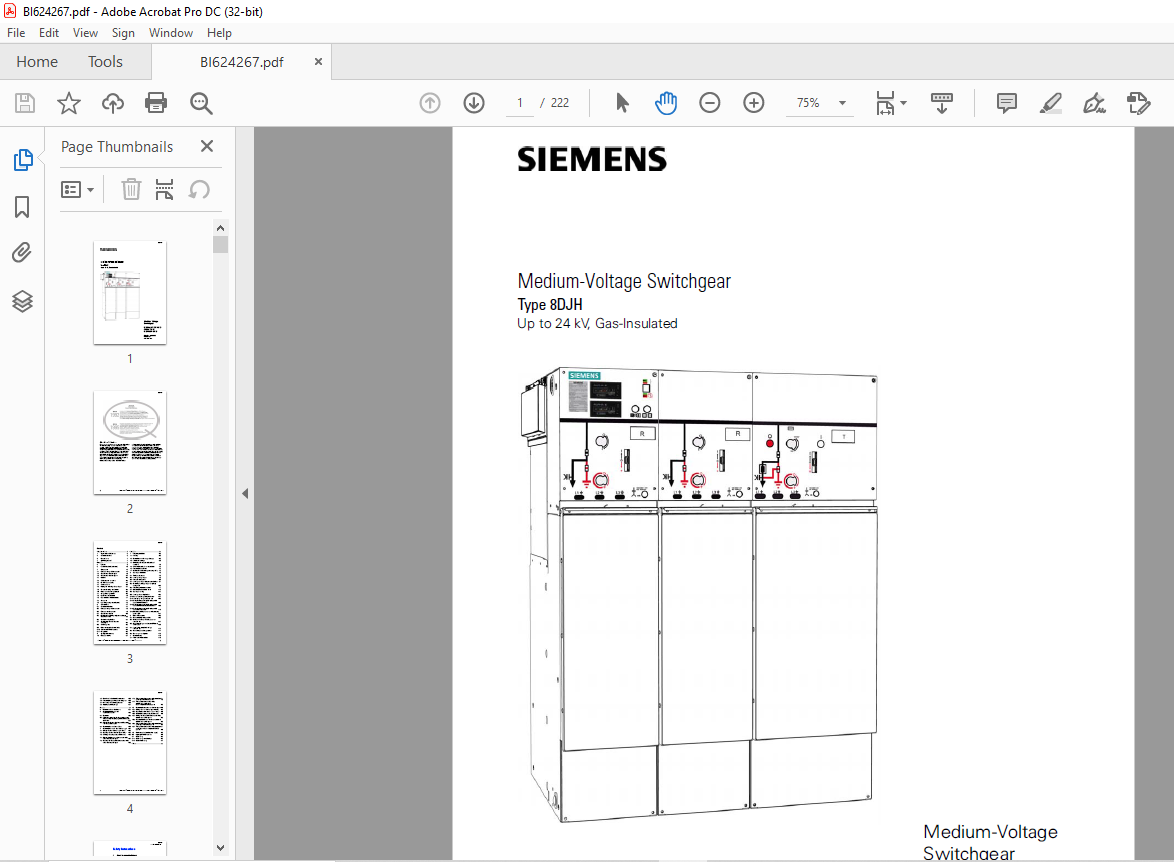

TABLE OF CONTENTS:
SIEMENS Medium-Voltage Switchgear Type 8DJH Cat INSTALLATION AND OPERATING INSTRUCTIONS MANUAL – PDF DOWNLOAD
Safety instructions 5
1 Signal terms and definitions 5
2 General instructions 6
3 Due application 7
4 Qualified personnel 7
Description 8
5 Features 8
6 Functional modules (selection) 10
7 Components 12
7 1 Three-position switch-disconnector 12
7 2 Vacuum circuit-breaker type 2 19
7 3 Vacuum circuit-breaker type 1 1 22
7 4 Interlocks 25
7 5 Cable compartment covers 26
7 6 HV HRC fuse assembly 27
7 7 Cable connection 30
7 8 Aligning and extending the switchgear 34
7 9 Current and voltage transformers 35
7 10 Protection and control equipment 36
7 11 Voltage detecting systems 36
7 12 Ready-for-service indicator 40
7 13 Short-circuit/earth-fault indicators 41
7 14 Accessories 44
7 15 Low-voltage compartment (option) 46
8 Technical data 47
8 1 General technical data 47
8 2 Three-position switch-disconnector 48
8 3 Three-position disconnector 49
8 4 Vacuum circuit-breaker 50
8 5 Classification of 8DJH switchgear according to
IEC/EN 62 271-200 53
8 6 Standards and guidelines 54
8 7 Switchgear versions – Dimensions
and weights 55
8 8 Gas leakage rate 56
8 9 Dielectric strength and site altitude 57
8 10 Selection of HV HRC fuse-links 58
8 11 Rating plates 65
9 Switchgear maintenance 66
10 End of service life 67
Installation 68
11 Preparing installation 68
11 1 Packing 68
11 2 Completeness and transport damage 68
11 3 Intermediate storage 69
11 4 Unloading and transport to the place of
installation 70
11 5 Checking the ready-for-service indicator 75
11 6 Preparing the foundation 76
11 7 Comments on electromagnetic compatibility 76
12 Switchgear installation 78
12 1 Tools/auxiliary means 78
12 2 Installing the switchgear 78
12 3 Pressure relief options 90
12 4 Installing switchgear with pressure absorber 91
12 5 Extending existing switchgear or replacing
components 108
12 6 Preparing panel interconnections 111
12 7 Mounting the busbar termination 118
12 8 Switchgear earthing 124
12 9 Installing the earthing busbar 125
12 10 Retrofit of motor operating mechanism 127
12 11 Installing low-voltage compartments 128
12 12 Billing metering panel type M with possible
connection busbar-busbar 130
12 13 Billing metering panel type M with possible
connection busbar-cable or cable-busbar 139
12 14 Billing metering panel type M with possible
connection cable-cable 149
12 15 Mounting earthing accessories in the metering
panel type M 157
13 Electrical connections 158
13 1 Connecting high-voltage cables 158
13 2 Cable connection with cable-type current
transformers 167
13 3 Connecting voltage transformers 4MT8 at the
cable feeder 169
13 4 Installing/removing busbar voltage
transformers 172
13 5 Connecting secondary equipment 177
13 6 Correcting circuit diagrams 178
14 Commissioning 179
14 1 Final tests after installation 179
BI624267
4 Revision 01 * INSTALLATION AND OPERATING INSTRUCTIONS 8DJH * 500-8384 9
14 2 Mechanical and electrical function test 180
14 3 Preparing the power-frequency voltage test 180
14 4 Instructing the operating personnel 180
14 5 Applying operating voltage 181
Operation 183
15 Indicators and control elements 184
16 Operating the three-position
switch-disconnector 185
16 1 Operations 186
16 2 Protection tripping for the three-position switchdisconnector
with spring-operated/stored-energy
mechanism 187
16 3 Ring-main and circuit-breaker panels: Operating
the three-position switch 188
16 4 Operating the transformer feeder 190
17 Operating the vacuum circuit-breaker type 2 194
17 1 Closing the circuit-breaker type 2 “locally” 195
17 2 Opening the circuit-breaker type 2 “locally” 195
17 3 Charging the spring energy store manually 196
17 4 Closing the three-position disconnector in the
circuit-breaker panel type 2 197
17 5 Opening the three-position disconnector in the
circuit-breaker panel type 2 198
17 6 Three-position disconnector in the circuit-breaker
panel type 2: EARTHED position 199
17 7 Three-position disconnector in the
circuit-breaker panel type 2:
Deactivating the EARTHED position 200
18 Operating the vacuum circuit-breaker type 1 1 201
18 1 Closing the circuit-breaker type 1 1 “locally” 202
18 2 Opening the circuit-breaker type 1 1 “locally” 203
18 3 Charging the spring energy store manually 203
18 4 Closing the three-position disconnector in the
circuit-breaker panel type 1 1 205
18 5 Opening the three-position disconnector in the
circuit-breaker panel type 1 1 206
18 6 Three-position disconnector in the circuit-breaker
panel type 1 1: EARTHED position 207
18 7 Three-position disconnector in the circuit-breaker
panel type 1 1: Deactivating the EARTHED
position 208
19 Verification of safe isolation from supply 209
20 Replacing HV HRC fuse-links 210
21 Cable testing 215
21 1 Cable testing via cable plugs 215
21 2 Cable sheath testing 217
Index 218
VIDEO PREVIEW OF THE MANUAL:
PLEASE NOTE:
- This is the same manual used by the dealers to diagnose and troubleshoot your vehicle
- You will be directed to the download page as soon as the purchase is completed. The whole payment and downloading process will take anywhere between 2-5 minutes
- Need any other service / repair / parts manual, please feel free to contact [email protected] . We still have 50,000 manuals unlisted
S.M