

Sakai soil Roller SV544 Shop Manual – PDF DOWNLOAD
The Sakai SV544 Soil Roller Shop Manual is essential for maintenance. Covering SV544 soil rollers, it ensures efficient servicing and repairs.
FILE DETAILS:
Sakai soil Roller SV544 Shop Manual – PDF DOWNLOAD
Language : English
Pages : 344
Downloadable : Yes
File Type : PDF
DESCRIPTION
Sakai soil Roller SV544 Shop Manual – PDF DOWNLOAD
Introduction
- This manual provides important information to familiarize you with safe operating and maintenance procedures for your SAKAI roller. Even though you may be familiar with similar equipment you must read and understand this manual before operating or servicing this unit.
- Safety is everyone’s business and it is one of your primary concerns. Knowing the guidelines presented in this manual will help provide for your safety, for the safety of those around you and for the proper operation and maintenance of the machine. Improper operation is dangerous and can result in injury or death. Sakai Heavy Industries cannot foresee all possible circumstances or varying conditions to which the operator, serviceman or machine may be exposed to that might lead to a potential hazard.
- Therefore, the warnings and cautions listed in this manual and those placed on the machine are not intended to be all inclusive and liability for personal injury or damage to equipment or property cannot be assumed. All information, specifications and illustrations in this publication are based on the product information available at the time that the publication was written. The contents may change without prior notice due to modifications of the model
VIDEO PREVIEW OF THE MANUAL:
IMAGES PREVIEW OF THE MANUAL:
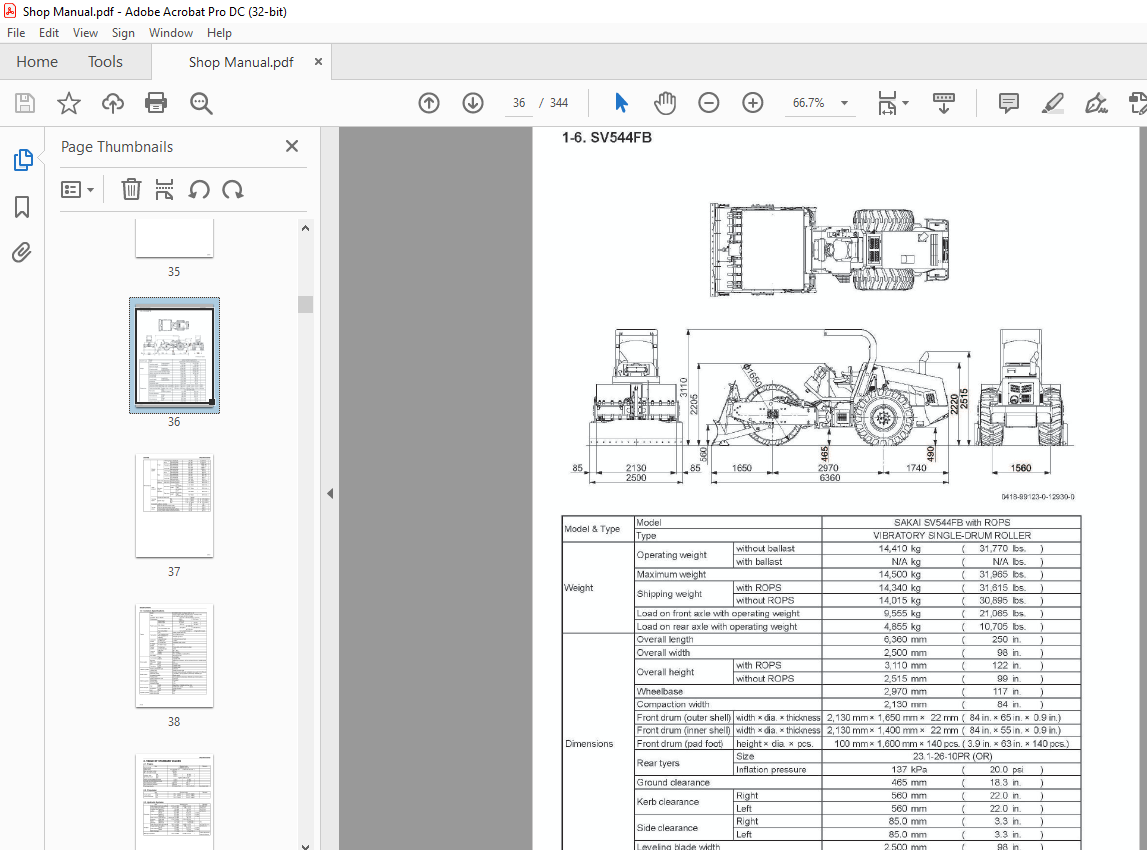
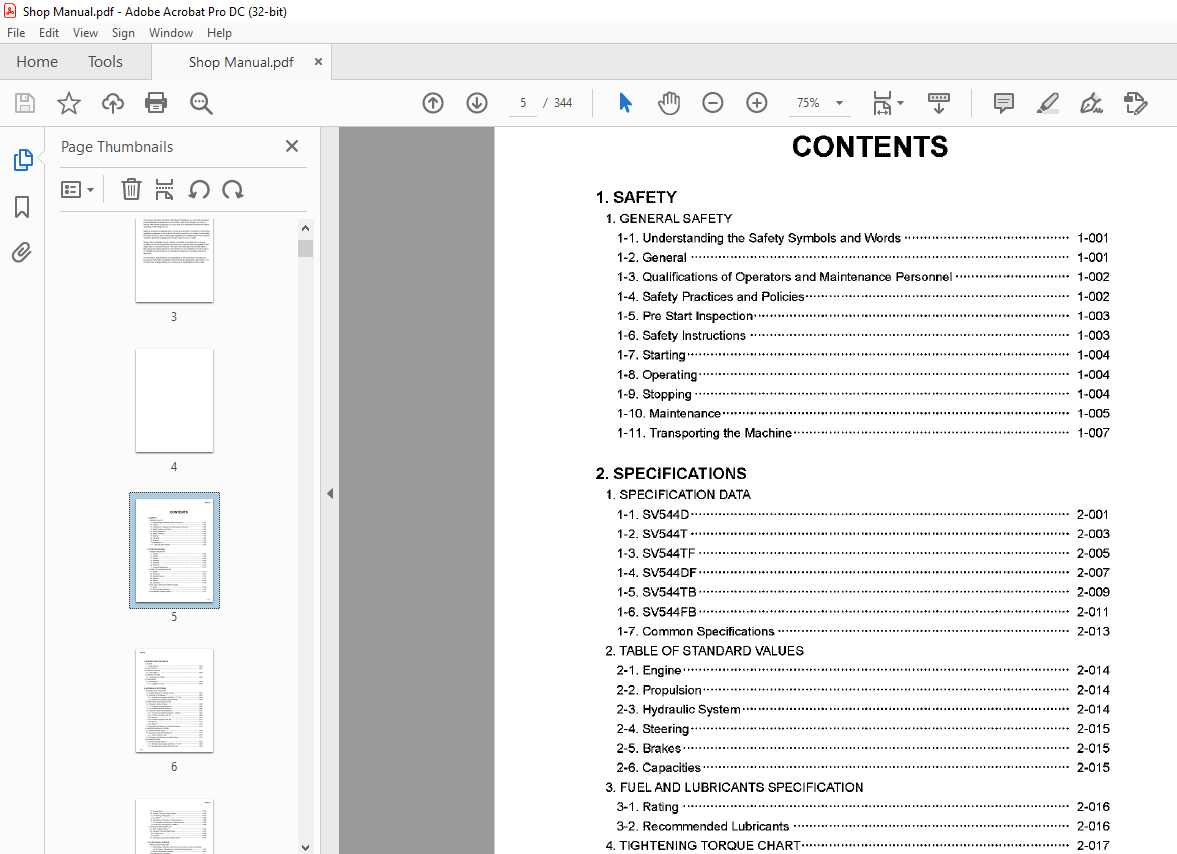
TABLE OF CONTENTS:
Sakai soil Roller SV544 Shop Manual – PDF DOWNLOAD
1 SAFETY
1 GENERAL SAFETY
11 Understanding the Safety Symbols and Words 1001
12 General 1001
1 3 Qualifications of Operators and Maintenance Personnel 1 002
14 Safety Practices and Policies 1002
15 Pre Start Inspection 1003
16 Safety Instructions 1003
17 Starting 1004
18 Operating 1004
19 Stopping 1004
110 Maintenance 1005
111 Transporting the Machine 1007
2 SPECIFICATIONS
1 SPECIFICATION DATA
11 SV544D 2001
12 SV544T 2003
13 SV544TF 2005
14 SV544DF 2007
15 SV544TB 2009
16 SV544FB 2011
17 Common Specifications 2013
2 TABLE OF STANDARD VALUES
21 Engine 2014
22 Propulsion 2014
23 Hydraulic System 2014
24 Steering 2015
25 Brakes 2015
26 Capacities 2015
3 FU ELAND LUBRICANTS SPECIFICATION
31 Rating 2016
32 Recommended Lubricants 2016
4 TIGHTENING TORQUE CHART 2017
0001
SV544@
0002
3 ENGINE AND CONTROLS
1ENGINE
11 Engine Mount 3001
2 FU EL SYSTEM 3002
3 EXHAUST SYSTEM
31 Urea System 3004
4 CONTROL SYSTEM
41 Forwardreverse Control 0
3006
5 PUMP MOUNT
51 Pump Mount 3007
511 Installation of pump 3008
4 HYDRAULIC SYSTEMS
1 SYSTEM CIRCUIT DIAGRAM
11 Graphic Symbols for Hydraulic Circuits 4001
12 Hydraulic Circuit Diagram 4003
121 Hydraulic circuit diagram (SV544D, T, TF, DF) 4003
122 Hydraulic circuit diagram (SV544TB, FB) 4004
2 PROPULSION HYDRAULIC SYSTEM
21 Propulsion Hydraulic Piping 4005
211 Propulsion hydraulic piping (F) 4005
212 Propulsion hydraulic piping (R) 4006
22 Hydraulic Component Specifications 4007
221 Hydraulic pump ASSY (propulsion+ vibrator) 4007
222 Propulsion hydraulic motor (F) 4009
223 Gear box 401 O
224 Propulsion hydraulic motor (R) 4011
225 Block (1) 4012
226 Block (2) 4013
23 Description and Operation of Propulsion System 4015
3 VIBRATOR HYDRAULIC SYSTEM
31 Vibrator Hydraulic Piping 4018
32 Hydraulic Component Specifications 4019
321 Vibrator hydraulic niotor 4019
33 Description and Operation of Vibrator System 4021
4 STEERING SYSTEM
41 Steering Hydraulic Piping 4022
411 Steering hydraulic piping (SV544D, T, TF, DF) 4022
412 Steering hydraulic piping (SV544TB, FB) 4023
SV544@
42 Steering \/\lheel 4024
43 Hydraulic Component Specifications 4025
431 Steering• charge pump 0
4025
432 Orbitrol 4026
44 Description and Operation of Steering System 4028
441 Description and operation of steering system 4028
442 Structure and operation of Orbitrol 4029
5 BLADE SYSTEM (SV544TB FB)
51 Blade Hydraulic Piping 4033
52 Hydraulic Component Specification 4034
521Stackvalve 4034
522 Valve 4035
53 Description and Operation of Blade System 4037
5 ELECTRICAL SYSTEM
1 PRECAUTIONS FOR WORK
11 Wire Numbers, Wire Sizes, Wire Colors and Connectors Shown in Electrical
Circuit Diagram, Wiring Harness Layout and Wiring Harnesses 5001
12 Electrical Equipment Installation 5002
2 SYSTEM CIRCUIT DIAGRAM
21 Electrical Circuit Diagram 5003
3 ELECTRICAL COMPONENTS
31 Wring Harness Layout (1) 5004
32 Wiring Harness Layout (2) 5005
4 WIRING HARNESSES
41 Fuse• Relay Harness 5006
42 Battery Relay Harness 5008
43 Panel Harness (1) 5010
44 Panel Harness (2)•• •••••• 5012
45 Engine Harness (1) 5014
46 Engine Harness (2) 5016
47 Engine Harness (3) 5018
48 SCR Harness 5020
49 Control Harness 5022
410 DEF Harness 5024
411 Speed Change Solenoid Harness 5025
412 Diagnostic Switch Harness 5026
413 Stater Switch Harness 5027
414 Disable Regeneration Harness 5028
415 FR Lever Vibration Switch Harness 5029
5 ELECTRICAL COMPONENT SPECIFICATIONS
51 Fuse Box (1) 5030
52 Fuse Box (2) 5031
53 Combination Meter 5032
6 VIBRATORY DRUM• REAR AXLE
1 PRECAUTIONS FOR DISASSEMBLY AND REASSEMBLY 6001
2 VIBRATORY DRUM
21 Removal and Installation of Vibratory Drum 6003
211 Removal of vibratory drum 6003
212 Installation of vibratory drum 6006
3 VIBRATORY DRUM ASSY
31 Vibratory Drum ASSY 6007
32 Disassembly and Reassembly of Vibratory Drum 6008
321 Disassembly of vibratory drum 6008
322 Reassembly of vibratory drum 6019
4 REAR AXLE
41 Rear Axle ASSY 6039
42 Rear Axle Lubrication 6040
43 Rear Axle Structure 6041
431 Center housing 6041
432 Differential 6042
433 Hub reduction gear 6043
434 Brake 6044
435 Gearbox 6045
7 BRAKE
1 BRAKE PEDAL 7001
2 BRAKE HYDRAULIC PIPING 7002
3 BRAKE SYSTEM
31 Description and Operation of Brake Circuit 7004
4 HYDRAULIC COMPONENT SPECIFICATIONS
41 Parking Brake Solenoid Valve 7005
42 Speed change Solenoid Valve (F) 7006
43 Servo Bypass Solenoid Valve 7007
44 Valve Block 7008
SV544@
8 INSPECTION AND ADJUSTMENT
1 INSPECTION AND ADJUSTMENT
11 Safety Precautions for Inspection and Adjustment 8001
12 Preparation for Inspection and Adjustment 8001
13 Precautions for Inspection and Adjustment 8001
14 \Narmup 8001
15 Inspection and Adjustment of Engine Related Items 8001
2 MEASUREMENT AND ADJUSTMENT OF PROPULSION CIRCUIT PRESSURE
21 Measurement 8002
22 Adjustment 8003
3 MEASUREMENT AND ADJUSTMENT OF PROPULSION CHARGE CIRCUIT
PRESSURE 8004
31 Measurement 8005
32 Adjustment 8006
4 MEASUREMENT OF MACHINE HIGH/LOW SPEED CHANGE CIRCUIT PRESSURE
41 Measurement of Propulsion Motor (F) 8007
42 Measurement of Propulsion Motor (R) 8008
5 MEASUREMENT OF PARKING BRAKE RELEASE PRESSURE
51 Measurement 8009
6 MEASUREMENT AND INSPECTION OF VIBRATOR CIRCUIT PRESSURE
61 Measurement 8010
62 Inspection 8011
7 MEASUREMENT AND ADJUSTMENT OF VIBRATOR CHARGE CIRCUIT
PRESSURE 8012
71 Measurement 8013
72 Adjustment 8014
8 MEASUREMENT OF VIBRATOR HIGH/LOW CHANGE CIRCUIT PRESSURE
81 Measurement 8015
9 MEASUREMENT AND INSPECTION OF STEERING CIRCUIT PRESSURE
91 Measurement 8016
92 Inspection 8017
10 MEASUREMENT AND INSPECTION OF BLADE CIRCUIT PRESSURE
(SV544TB, FB)
101 Measurement 8018
102 Inspection 8019
11 MEASUREMENT OF HYDRAULIC PUMP CASE PRESSURE
111 Measurement of Propulsion Pump Case Pressure 8020
112 Measurement of Vibrator Pump Case Pressure 8021
12 MEASUREMENT OF PROPULSION MOTOR CASE PRESSURE
121 Measurement of Propulsion Motor (F) 8022
122 Measurement of Propulsion Motor (R) 8023
13 MEASUREMENT OF VIBRATOR MOTOR CASE PRESSURE
131 Measurement 8024
14 ADJUSTMENT OF FR LEVER LINKAGE
141 Adjustment 8025
15 BRAKE ADJUSTMENT
151 Manually Releasing the Brake 8026
152 Adjustment after Manual Release of Brake 8027
9 TROUBLESHOOTING
1 TROUBLESHOOTING
11 Safety Precautions for Troubleshooting • , , , , 9001
12 Important Information for Troubleshooting 9001
13 Before Starting 9002
2 ELECTRICAL SYSTEM TROUBLESHOOTING
21 \Mien Performing Electrical System Fault Diagnosis 9003
211 Precautions to take during electrical circuit fault diagnosis , 9003
212 Inspection procedures using a tester 9004
213 Inspection of electrical system 9009
22 Engine Diagnosis Trouble Code 9011
221 Description of fault code (SPN FM I) 9011
222 Fault code list , , , 9012
23 Error Codes 9033
24 Engine 9035
241 Engine will not start (Starter motor does not run) 1/3 9035
241 Engine will not start (Starter motor does not run) 2/3 9037
241 Engine \Viii not start (Starter motor does not run) 313 9039
242 No charging 9041
243 Grid heater dose not work
(Engine starting performance is bad in cold weather) 9041
244 Starter motor runs even when FR lever is not at N
and parking brake is not applied , , , 9043
245 Engine speed cannot be switched 9043
25 Propulsion 9045
251 Machine moves neither forward nor backward 1/3 9045
251 Machine moves neither forward nor backward 2/3 9047
251 Machine moves neither forward nor backward 3/3 9049
SV544@
252 Machine speed cannot be changed 9049
253 Travel mode cannot be changed 1/2 9051
253 Travel mode cannot be changed 2/2 9053
254 Brake cannot be released 1/2 9055
254 Brake cannot be released 2/2 9057
255 Brake does not vVOrk 9059
26 Vibration 9061
261 No vibration occurs 1/3 , 9061
261 No vibration occurs 2/3 9063
261 No vibration occurs 3/3 9065
262 Amplitude does not change (Remains either Low or High) 113 9067
262 Amplitude does not change (Remains either Low or High) 213 9069
262 Amplitude does not change (Remains either Low or High) 313 9071
263 Vibration mode cannot be switched
(FR lever vibration switch does not work) 9073
264 Vibrator force is low in ECO mode 9075
27 Lighting 9077
271 Illumination of combination meter does not light 9077
272 Combination meter warning lamp or indicator lamp is abnormal 9079
273 Hour meter is abnormal 9081
274 Fuel meter is abnormal 9081
275 Hydraulic oil filter warning lamp remains ON 9083
276 Vibration indicator lamp does not light 9085
277 ECO mode indicator lamp does not light, 9087
278 Parking brake indicator lamp does not light 9087
279 Horn does not sound 9089
2710 Backup buzzer does not sound 9089
3 HYDRAULIC SYSTEM TROUBLESHOOTING
31 \1\/hen Performing Hydraulic System Troubleshooting 9090
32 Propulsion System 9091
321 Machine moves neither forward nor backward 1/2 9091
321 Machine moves neither forward nor backward 2/2 9092
322 Machine moves in one direction only (forward or backward) 9092
323 Slow machine speed or small drive force 1/2 9092
323 Slow machine speed or small drive force 2/2 9093
324 Machine speed cannot be switched 9093
325 Machine does not stop completely with FR lever in N 9093
326 Propulsion system is overheating 9094
327 Abnormal noise from propulsion system 9094
33 Vibrator System 9095
331 No vibration 9095
332 Vibrator frequency is too low 9096
333 Amplitude does not switch between high and low 9096
334 Vibrator does not stop 9097
335 Vibrator system is overheating 9097
336 Abnormal noise from vibrator system 9097
34 Steering System 9098
341 Steering wheel is hard to turn 9098
342 Steering response is slow 9098
343 Steering wheel backlash or play is large 9099
344 Steering system is overheating 9099
345 Abnormal noise from steering system 9099
35 Blade (SV544TB FB) 9100
351 Blade up/doVvn operation not possible 9100
352 Blade movement is slow or force is small 9100
353 Blade floating operation not possible 9101
354 Blade hydraulic system is overheating 9101
355 Abnormal noise from blade hydraulic system 9101
S.M 3/24


