

OM PIMESPO XLOGO1 XLOGO2 Series 4539 – 4549 Workshop Manual – PDF DOWNLOAD
FILE DETAILS:
OM PIMESPO XLOGO1 XLOGO2 Series 4539 – 4549 Workshop Manual – PDF DOWNLOAD
Language : English
Pages : 226
Downloadable : Yes
File Type : PDF
DESCRIPTION:
OM PIMESPO XLOGO1 XLOGO2 Series 4539 – 4549 Workshop Manual – PDF DOWNLOAD
Product information
Instruction and maintenance manual
This chapter gives information taken from the instruction and maintenance manual, considered as of interest for the assistance technician
IMAGES PREVIEW OF THE MANUAL:
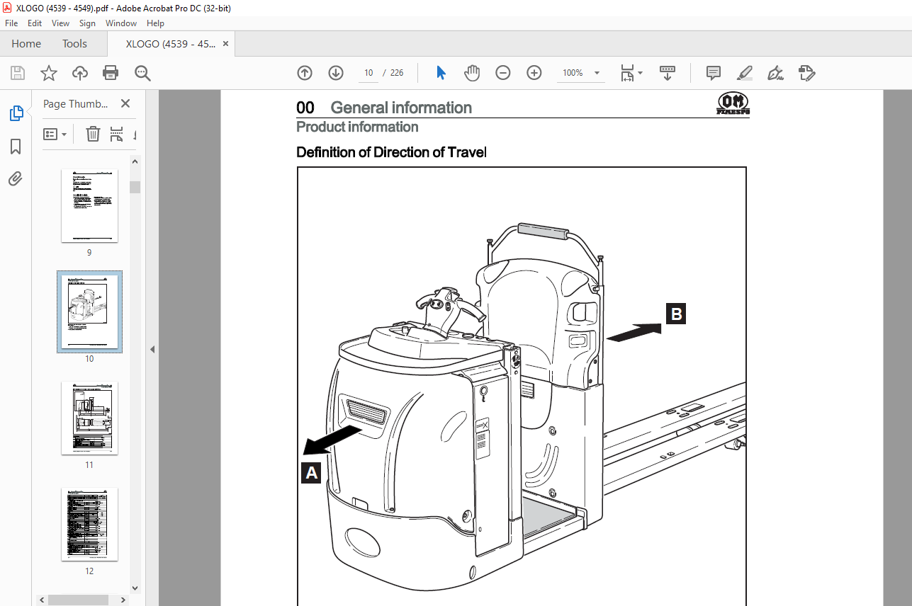
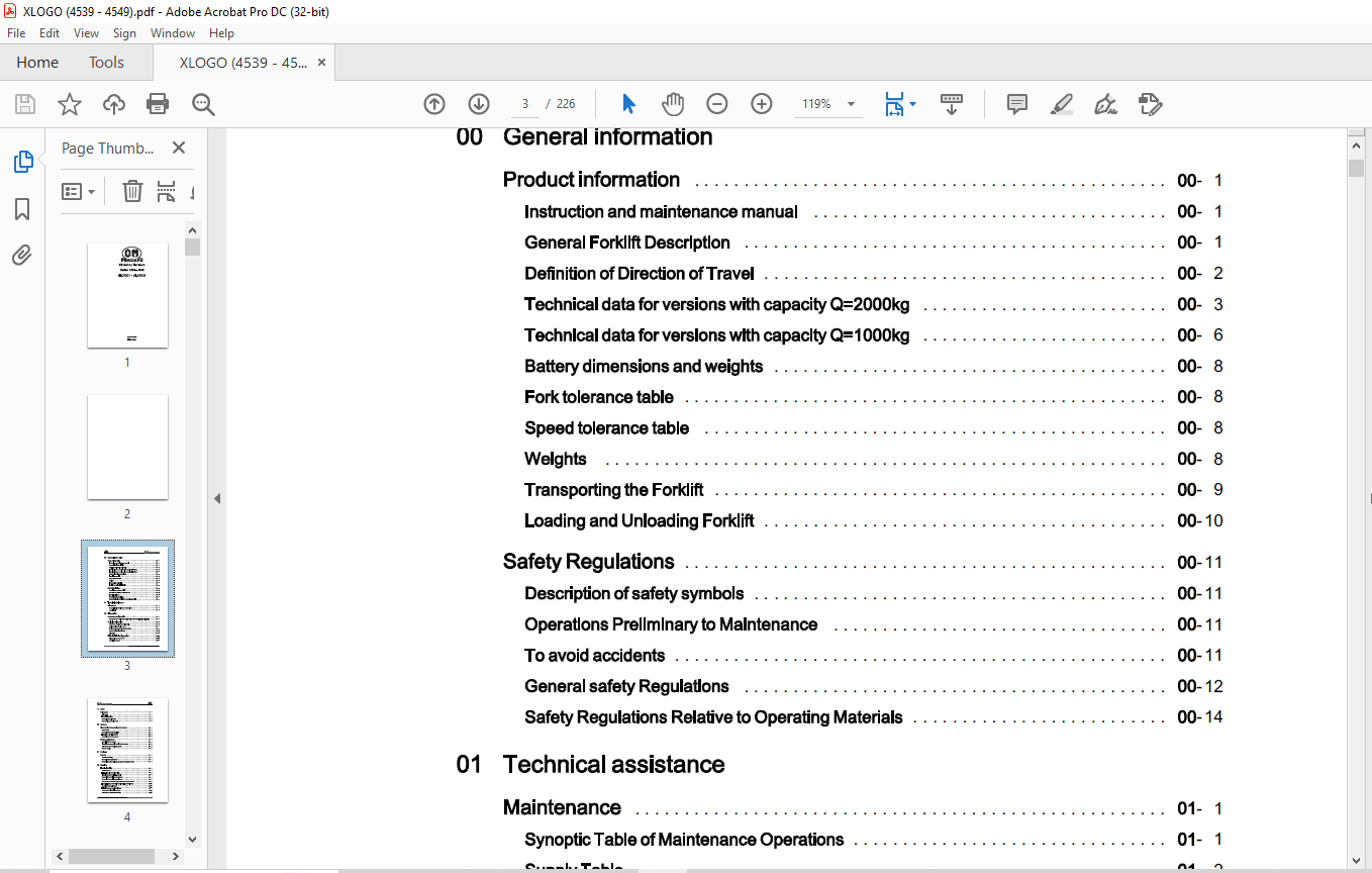

TABLE OF CONTENTS:
OM PIMESPO XLOGO1 XLOGO2 Series 4539 – 4549 Workshop Manual – PDF DOWNLOAD
00 General information
Product information
Instruction and maintenance manual
General Forklift Description
Definition of Direction of Travel
Technical data for versions with capacity Q=2000kg
Technical data for versions with capacity Q=1000kg
Battery dimensions and weights
Fork tolerance table
Speed tolerance table
Weights
Transporting the Forklift
Loading and Unloading Forklift
Safety Regulations
Description of safety symbols
Operations Preliminary to Maintenance
To avoid accidents
General safety Regulations
Safety Regulations Relative to Operating Materials
01 Technical assistance
Maintenance
Synoptic Table of Maintenance Operations
Supply Table
02 Diagnostics
Connectors for diagnostics
Table of content
Connectors for “Curtis” system diagnostics and for the “LES electrical drive”
Curtis plant diagnostics
Software for Curtis system diagnostics
Device monitor (Monitor menu)
“Device parameters” (Parameters Menu)
System fault monitor (Alarms)
Alarms list
“LES electrical drive diagnostics”
Diagnostics by means of PC
Description of menu
II Workshop literature 45398042301 EN 03/2006
Table of contents {Oi,}
PUIESPD
11 Motor
Drive motor 11
Drive motor 11
Technical data plate 11
Removal of the drive motor 11
Reassembly of the drive motor 11
22 Reducer
Disassembly/ Reassembly of the reducer 22
Disassembly 22
Removal of the anchorage plate 22
Extraction of the drive reducer 22
Assembly of the reducer group 22
Reducer maintenance 22
Description of the reducer 22
Instructions for assembly/ service on the reducer 22
Adjustment of the bevel gear system 22
Reducer section 22
31 Carriage
Bonnets 31
Internal accessibility 31
Removal of the upper bonnet 31
Removal of the gas spring on the battery compartment cover 31
42 Steering
Electrical steering 42
Steering system 42
L.E.S. electronic control module 42
Inputs-Outputs of the L.E.S. control 42
Removal of the steering motor reducer 42
Removal of the steering potentiometer 42
Reassembly of the steering potentiometer and motor reducer 42
Electrical diagram of the drive wheel position potentiometer 42
Cantering the potentiometer 42
L.E.S. interface connection diagram 42
Access to the diagnostics software 42
Workshop literature 45398042301 EN 03/2006 III
~ PIJIESPII Table of contents
Steering potentiometer calibration check 42
Drive wheel potentiometer calibration check 42
Adjustment of L.E.S. sensitivity 42
Tiller 42
Remove the steering potentiometer on the shaft 42
Removal of shaft head 42
Removal of the shaft potentiometer group 42
Technical information regarding the drive accelerator potentiometer 42
Removal of the horn button 42
Removal of the consent buttons 42
Removal of the ascent-descent buttons 42
Removal of the shaft card 42
Technical information regarding the electronic card for the shaft 42
Removal of the platform ascent-descent button 42
Shaft head assembly 42
Removal of the shaft head from the forklift 42
Removal of the shaft support housing 42
Reassembly of the shaft support housing 42
46 Wheels and lever systems
Wheels 46
Wheel Wear Check 46
Replacement of the drive wheel 46
Wheel Tightening Check 46
Removal of the stabiliser wheel 46
Reassembly of the stabiliser wheel 46
Pivot wheel oil level check 46
Swivelling wheel oil change and topping up 46
Fork lifting lever system 46
49 Braking
Braking devices and methods 49
Braking devices and methods 49
Motor braking 49
Electromagnetic brake 49
To check wear and adjustment of the electromagnetic brake 49
IV Workshop literature 45398042301 EN 03/2006
Table of contents {Oi,}
PUIESPD
Service braking (eABS) 49
Description of service braking ( eABS) 49
Features of the eABS module 49
eABS module inputs and outputs 49
Alarms encoding 49
List of alarms 49
60 Electrical and electronic system
Electrical-electronic system in general. 60
Diagram of the functions of the “Curtis electronic control system” 60
Main features of the Curtis system 60
Inputs and outputs of the “Curtis system” 60
Temperature control 60
Removal of Curtis three-phase drive system 60
Disassembly of the complete system support 60
Wiring 60
Fuses:location, check, replacement 60
Adjustment of the dashboard microswitch control screw 60
Batteries 60
Removal of the battery status indicator and counter 60
Low battery charge indicator and counter 60
Battery Replacement 60
Stands with rollers for lateral battery extraction (option) 60
Electrolyte Level and Density Check 60
Battery Recharging 60
70 Hydraulic system
Hydraulic diagrams 70
Hydraulic connection diagram for fixed platform 70
Hydraulic connection diagram for mobile platform and capacity of 2000 Kg 70
Hydraulic connection diagram for mobile platform with capacity of 1000 Kg 70
Electromagnetic valves group, capacity=1000kg 70
Electromagnetic valves group, capacity=2000kg 70
71 Hydraulic components
Control unit and accumulator 71
Replacement of the hydraulic control unit 71
Removal of mobile platform accumulator 71
Hydraulic System Oil Level Check
80 Lifting
Fork lifting
Removal of the fork lifting cylinder
Removal of the supply pipe to the fork lifting cylinder
Platform
Shimming the lateral runner of the mobile platform
Adjust and replace the rubber buffers at the platform stroke end.
Cylinders
Drawing offorks lifting cylinder (capacity=2000Kg h3=125mm)
Drawing of forks lifting cylinder ( capacity= 1000Kg_h3=840mm)
Fork lifting cylinder servicing : Disassembly
Fork lifting cylinder servicing : Reassembly
Drawing of the platform lifting cylinder
Removal of platform lifting cylinder
Removal of the platform cylinder supply pipe
Fixed platform electrical connection diagram – sheet 1 /4
Fixed platform electrical connection diagram – sheet 2/4
Fixed platform electrical connection diagram – sheet 3/4
Fixed platform electrical connection diagram – sheet 4/4
Mobile platform electrical connection diagram – sheet 1/4
Mobile platform electrical connection diagram – sheet 2/4
Mobile platform electrical connection diagram – sheet 3/4
Mobile platform electrical connection diagram – sheet 4/4
VIDEO PREVIEW OF THE MANUAL:
PLEASE NOTE:
- This is the SAME exact manual used by your dealers to fix your vehicle.
- The same can be yours in the next 2-3 mins as you will be directed to the download page immediately after paying for the manual.
- Any queries / doubts regarding your purchase, please feel free to contact [email protected]
S.M


