

OM Pimespo TN Type 4526 CNType 4525 CNS Type 4527 CNi Type 4528 Workshop Manual – PDF DOWNLOAD
FILE DETAILS:
OM Pimespo TN Type 4526 CNType 4525 CNS Type 4527 CNi Type 4528 Workshop Manual – PDF DOWNLOAD
Language : English
Pages : 350
Downloadable : Yes
File Type : PDF
DESCRIPTION:
OM Pimespo TN Type 4526 CNType 4525 CNS Type 4527 CNi Type 4528 Workshop Manual – PDF DOWNLOAD
General Rules
Avoiding Accidents
Most accidents that take place in workshops are caused by the non-compliance with some simple and basic care and safety rules. That is why in most cases, they could be avoided: their probable causes should be envisaged and, therefore, caution and care are required during operation. It is impossible to fully exclude all possible accidents for any kind of equipment, however welldesigned and manufactured it may be. A careful and wise mechanician is the best guarantee against accidents. The scrupulous compliance with a single and simple safety rule should be more than enough to avoid
IMAGES PREVIEW OF THE MANUAL:

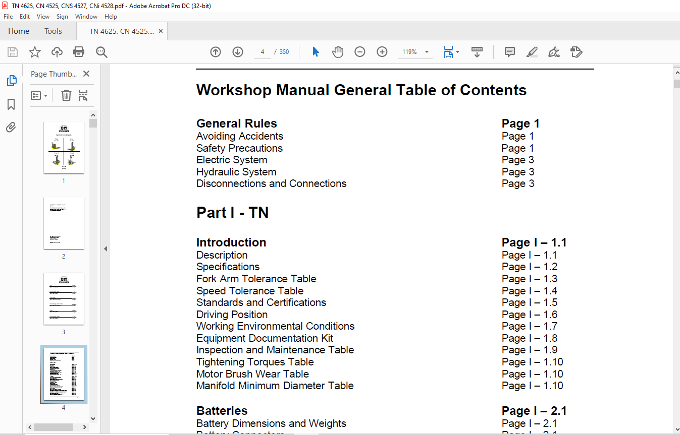
TABLE OF CONTENTS:
OM Pimespo TN Type 4526 CNType 4525 CNS Type 4527 CNi Type 4528 Workshop Manual – PDF DOWNLOAD
Workshop Manual General Table of Contents
General Rules Page 1
Avoiding Accidents Page 1
Safety Precautions Page 1
Electric System Page 3
Hydraulic System Page 3
Disconnections and Connections Page 3
Part I – TN
Introduction Page I – 1 1
Description Page I – 1 1
Specifications Page I – 1 2
Fork Arm Tolerance Table Page I – 1 3
Speed Tolerance Table Page I – 1 4
Standards and Certifications Page I – 1 5
Driving Position Page I – 1 6
Working Environmental Conditions Page I – 1 7
Equipment Documentation Kit Page I – 1 8
Inspection and Maintenance Table Page I – 1 9
Tightening Torques Table Page I – 1 10
Motor Brush Wear Table Page I – 1 10
Manifold Minimum Diameter Table Page I – 1 10
Batteries Page I – 2 1
Battery Dimensions and Weights Page I – 2 1
Battery Connectors Page I – 2 1
Additional Socket Kit for Double Shifts Page I – 2 1
Battery Replacement Page I – 2 2
Battery Fixed/Movable Rack Page I – 2 2
Battery Removal Page I – 2 3
Installing the battery Page I – 2 3
Built-in Rectifier Page I – 2 4
Socket and Plug Table Page I – 2 5
Equipment Main Casing Page I – 3 1
Dashboard-Controls-Instrument System Page I – 3 1
Mushroom-Head Emergency Button Page I – 3 1
Start-up Switch Page I – 3 1
I B S + Hour Counter Instrument Page I – 3 2
Access Compartment to the Battery Charger Cable Page I – 3 3
Fairings Page I – 3 4
Standard enlarded DIN battery compartment hood Page I – 3 4
Standard narrow DIN battery compartment hood Page I – 3 4
Motor compartment hood Page I – 3 4
Motor Compartment Bonnet Removal Page I – 3 5
Page 2
Battery Cover Removal Page I – 3 7
Separation of Frames Page I – 3 8
View from operator side Page I – 3 10
Forks side view Page I – 3 11
Side view Page I – 3 12
Side top view Page I – 3 13
Traction Unit Page I – 4 1
Traction Speed Page I – 4 1
Traction Stoppage Page I – 4 1
Traction Motor Page I – 4 2
Reduction Unit Overhauling Page I – 4 3
2,200 Kg Traction Unit Assembly Diagram Page I – 4 8
3,000 Kg Traction Unit Assembly Diagram Table Page I – 4 10
Braking System Page I – 5 1
Electromagnetic Brake Page I – 5 1
Electromagnetic Brake Calibration Table Page I – 5 2
Description of E M B Plates Page I – 5 3
Power, Voltage, Coil Resistance Page I – 5 4
Tools to be used for E M B Page I – 5 5
Assembling of the Clutch Disk for Measures 06-16 Page I – 5 6
Brake Flange Assembling Page I – 5 6
E M B Assembling Steps Page I – 5 7
Rubber Protection Assembling Page I – 5 9
Electrohydraulic Brake (Optional) Page I – 5 10
Electric (Regenerating) Braking Page I – 5 10
E M B Assembling Diagram Page I – 5 11
E M B Cable Diagram Page I – 5 12
Rollers and Levers Page I – 6 1
Load Rollers and Pallet Intake Rollers Page I – 6 1
Lever Removing Page I – 6 2
Lever Bush Removal and Replacement Page I – 6 9
Lever Assembling Page I – 6 11
Tiller Unit Page I – 7 1
Tiller Head Controls Page I – 7 1
Tiller Casing Page I – 7 1
Connection Diagram between Tiller Card and COMBI System Page I – 7 2
Traction Control Butterfly Page I – 7 3
Traction Accelerator Potentiometer Page I – 7 3
The Redundant Potentiometer Page I – 7 4
Tiller Safety Device Button Page I – 7 4
Tiller Head Buttons Page I – 7 5
Tiller Positions Page I – 7 6
Traction Potentiometer Replacement Page I – 7 7
Traction Control Diagram Page I – 7 12
Traction Control Diagram Page I – 7 14
Page 3
Tiller Board Diagram Page I – 7 16
Tiller Cable Harness Diagram Page I – 7 18
Lifting System Page I – 8 1
Lifting, Lowering and Interlock Devices Page I – 8 1
Hydraulic Unit Motor Page I – 8 1
TN 2,200 Kg Hydraulic Lifting Diagram Page I – 8 2
TN 3,000 Kg Hydraulic Lifting Diagram Page I – 8 3
Motor-driven Pump Removal Page I – 8 6
Motor-driven Pump Unit Assembling Page I – 8 8
Lifting Cylinder Removal Page I – 8 9
Lifting Cylinder Overhauling Page I – 8 12
Lifting Cylinder Assembly Page I – 8 16
Lifting Cylinder Assembly Table Page I – 8 16
Lifting Cylinder Assembling Page I – 8 17
Wheels Page I – 9 1
Driving Wheel Page I – 9 1
Slick Tyre Driving Wheel Model Page I – 9 1
Traction Wheel Replacement Page I – 9 1
Pivoting wheel unit Page I – 9 3
Complete pivoting wheel assembly (lateral view) Page I – 9 3
Complete pivoting wheel assembly (front view) Page I – 9 4
Wheel assembly Page I – 9 5
Removing the pivoting wheel Page I – 9 6
Lubrication Page I – 10 1
Reduction Unit Oil Topping Up Page I – 10 1
Hydraulic Oil Topping Up (Hydraulic Unit and Pivoting Wheels) Page I – 10 2
Greasing Page I – 10 3
Lubricant Table Page I – 10 5
COMBI System Page I – 11 1
COMBI Specifications Page I – 11 1
COMBI System Assembly Page I – 11 3
Armature Pilot System Diagram Page I – 11 4
Field Pilot System Diagram Page I – 11 5
Pump Motor Pilot System Diagram Page I – 11 7
Energy Regeneration Page I – 11 8
COMBI Diagnostic Page I – 11 9
Parameter Change Page I – 11 11
Signal Monitoring Page I – 11 12
Accelerator Voltage Programming Page I – 11 13
Stored Alarms Page I – 11 14
Configurations Page I – 11 14
Adjustments Page I – 11 14
Additional Functions Page I – 11 15
Special Adjustments Page I – 11 15
Alarms Page I – 11 16
Page 4
COMBI System EPROM Replacement Page I – 11 19
COMBI System Input/Output Diagram for TN Page I – 11 23
Electric System Page I – 12 1
Sheathes and Connectors Page I – 12 1
Wiring Diagram Page I – 12 2
Optionals Page I – 13 1
Summary Table Page I – 13 1
Page 5
Diagram list for TN in A3 format
452106010 Sockets and connectors table
452249553 Serial tiller board
452606008 Electronic controller inputs / outputs diagram
452606001 Cables and harnesses positioning diagram
452606010 Electrical connections diagram
452606009 Automotive harness diagram
452606003 Sensor harness
452206030 Parameters settino table
Page 6
Part II – CN-CNS
Introduction Page II – 1 1
Description Page II – 1 1
Specifications Page II – 1 2
Forklift and Fork Arm Tolerance Table Page II – 1 7
Forklift Verticality Tolerance Table Page II – 1 7
Speed Tolerance Table Page II – 1 7
Standards and Certifications Page II – 1 8
Driving Position Page II – 1 9
Working Environmental Conditions Page II – 1 10
Equipment Documentation Kit Page II – 1 11
Additional Documentation Kit Page II – 1 11
Inspection and Maintenance Table Page II – 1 12
Tightening Torques Table Page II – 1 13
Batteries Page II – 2 1
Battery Dimensions and Weights Page II – 2 1
Battery Connectors Page II – 2 1
Additional Socket Kit for Double Shifts Page II – 2 1
Battery Replacement Page II – 2 2
Battery Fixed/Movable Rack Page II – 2 2
Built-in Rectifier Page II – 2 3
Socket and Plug Table Page II – 2 4
Equipment Main Casing Page II – 3 1
Dashboard Controls e Instrument System Page II – 3 1
Mushroom-Head Emergency Button Page II – 3 1
Start-up Switch Page II – 3 1
I B S + Hour Counter Instrument Page II – 3 2
Access Compartment to the Battery Charger Cable (Optional) Page II – 3 4
Motor Compartment Bonnet Removal Page II – 3 5
Battery Cover Removal Page II – 3 7
Bonnet and Cover Assembling Page II – 3 7
Position if the identification plates and stickers Page II – 3 8
View from operator side Page II – 3 8
View from forks side Page II – 3 9
Lateral view Page II – 3 10
View from above Page II – 3 11
Traction Unit Page – 4 1
Traction Speed Page II – 4 1
Traction Stoppage Page II – 4 1
Traction Motor Page II – 4 1
Overhaul of reduction gear unit Page II – 4 2
Traction Unit Assembly Diagram Page II – 4 7
Page 7
Braking System Page II – 5 1
Electromagnetic Brake Page II – 5 1
Electromagnetic Brake Calibration Table Page II – 5 1
Description of electromagnetic brake Page II – 5 2
Description of E M B dataplates Page II – 5 3
Power; Voltage, Coil Resistance Page II – 5 4
Tools required for E M B Page II – 5 5
Installation of clutch disk for sizes 06-16 Page II – 5 6
Installation of brake flange Page II – 5 6
Assembly phases of E M B Page II – 5 7
Fitting the rubber guard Page II – 5 9
Electro-hydraulic brake (Optional) Page II – 5 10
Electric braking (regenerative) Page II – 5 10
E M B Assembling Diagram Page II – 5 11
E M B Cable Diagram Page II – 5 12
Rollers and Levers Page II – 6 1
Load Rollers Page II – 6 1
Load Roller Removing Page II – 6 2
Load Roller Assembling Page II – 6 4
Tiller Unit Page II – 7 1
Tiller Head Controls Page II – 7 1
Tiller Casing Page II – 7 1
Connection Diagram between Tiller Card and COMBI System Page II – 7 2
Traction Control Butterfly Page II – 7 3
Traction Accelerator Potentiometer Page II – 7 3
The Redundant Potentiometer Page II – 7 4
Lifting/Lowering Control Butterfly Page II – 7 4
Lift and lower speed control potentiometer Page II – 7 5
Tiller Safety Device Button Page II – 7 5
Tiller Head Buttons Page II – 7 5
Tiller Positions Page II – 7 6
Tiller Head Assembly Page II – 7 7
Tiller Head Assembly Table Page II – 7 9
Lift/lower potentiometer diagram Page II – 7 10
Tiller functions diagram Page II – 7 12
Tiller Card Connection Diagram Page II – 7 14
Lifting System Page II – 8 1
Lifting, Lowering and Interlock Devices Page II – 8 1
Hydraulic Unit Motor Page II – 8 1
Hoister Page II – 8 1
Simplex Hydraulic Diagram Page II – 8 2
Duplex PAL Hydraulic Diagram Page II – 8 4
Duplex/Triplex GAL Hydraulic Diagram Page II – 8 6
Proportional Valve Page II – 8 8
2 2 KW Hydraulic Unit Assembly Page II – 8 10
Page 8
3 KW Hydraulic Unit Assembly Page II – 8 12
Hydraulic Unit and Tank Removal Page II – 8 14
Proportional Valve Removal Page II – 8 17
Proportional Valve Overhauling Page II – 8 18
Lifting Cylinder Overhauling Page II – 8 20
Wheels Page II – 9 1
Drive wheel Page II – 9 1
Drive wheel variant in smooth rubber Page II – 9 1
Traction Wheel Replacement Page II – 9 1
Pivoting wheel unit Page II – 9 3
Complete pivoting wheel assembly (lateral view) Page II – 9 3
Complete pivoting wheel assembly (front view) Page II – 9 5
Wheel assembly Page II – 9 6
Removing the pivoting wheel Page II – 9 7
Lubrication Page II – 10 1
Oil and Grease Supply for the Standard Version Page II – 10 1
Oil and Grease Supply for the Cold-Storage Room Version Page II – 10 1
General Lubrication Page II – 10 1
Greasing the reduction gear unit axial thrust bearing Page II – 10 2
Topping up the hydraulic oil Page II – 10 3
COMBI System Page II – 11 1
COMBI System Input/Output Diagram CN-CNS Page II – 11 2
Electric System Page II – 12 1
Functional Diagram Page II – 12 1
Optionals Page II – 13 1
Summary table Page II – 13 1
Page 9
Diagram list for CN-CNS in A3 fomat
452106010 Sockets and connectors table
452249553 Serial tiller board
452506003 Electronic controller inputs / outputs diagram
452506001 Cables and harnesses positioning diagram
452506004 Electrical connections diagram
452506005 Automotive harness diagram
452506006 Tiller sensor harness
452506030 Parameters setting table
452606004 E M B cable diagram
452249551 Complete fully-assembled traction control unit
452249552 Traction potentiometer
452649101 S A tiller harness
Page 10
Part III – CNi
5 “COMBI” digital electronic control 1
5 1 Functional diagram of the new 4528 series 1
5 2 COMBI technical features 2
DIAGNOSTICS: 3
5 3 COMBI diagnostics 4
5 3 1 Parameter Change: 6
5 3 2 Signal monitoring 7
5 3 3 Programming the accelerator voltage (same as the CN) 8
5 3 4 Stored alarms (same as the CN) 8
5 3 5 Configurations (same as the CN) 8
5 3 5 1 Adjustments (same as the CN) 8
5 3 5 2 Additional functions 8
8 2 1 Emergency lowering of the forks 10
Drawings list:
45283801000 Main sheath diagram
45358081200 Standard tiller buttons assembly diagram
45358081201 Standard tiller buttons wiring diagram
Overall assembly diagram of the tiller buttons with the
“tiller always ON” option
45288081201
Wiring diagram of the tiller buttons with the “tiller
always ON” option
45288020000 Overall wiring diagram
Overall diagram of the electronic panel with
inputs/outputs
45288020200 Hydraulic system wiring diagram
45288080501 Overall view of the components under the hoods
VIDEO PREVIEW OF THE MANUAL:
PLEASE NOTE:
- This is the SAME MANUAL used by the dealerships to diagnose your vehicle
- No waiting for couriers / posts as this is a PDF manual and you can download it within 2 minutes time once you make the payment.
- Your payment is all safe and the delivery of the manual is INSTANT – You will be taken to the DOWNLOAD PAGE.
- So have no hesitations whatsoever and write to us about any queries you may have : heydownloadss @gmail.com
S.M


