

OM FOUR-D Series X049 Workshop Manual – PDF DOWNLOAD
FILE DETAILS:
OM FOUR-D Series X049 Workshop Manual – PDF DOWNLOAD
Language : English
Pages :124
Downloadable : Yes
File Type : PDF
DESCRIPTION:
OM FOUR-D Series X049 Workshop Manual – PDF DOWNLOAD
General Recommendations
Avoiding accidents
The vast majority of accidents in workshops are caused by lack of observance of simple and basic rules of safety . For this reason a large part of them can be avoided: it is enough to anticipate their possible causes and take steps to apply caution and prudence required. As with every type of machine it is not possible to exclude in absolute every possible potential dangerous situation. A careful and safe technician is the best security against accidents. The respect of a single and basic safety rule would be more than enough to avoid many serious accidents.
Safety rules
In general
Carefully follow the procedure for maintenance and repair
- Do not use rings, watches, loose clothing such as ties, torn overalls or scarves, undone jackets, unzipped blouses that can get into moving parts. It is advisable to wear clothing designed to reduce accidents: helmets, non slip shoes, gloves, safety goggles.
- Do not carry out any repairs on the machine with people sitting on the truck unless they are the usual operators and are helping with the operation in hand. Do not use the machine or its attachments from a position other than the driving one. Ensure that there is no pressure inside hydraulic circuit before opening plugs and covers. Read the instructions in this manual.
- All works must be carried out with the greatest care and attention. All stepladders and platforms used in the workshop or field must conform to the safety requirement in force. Label all controls to indicate that there is maintenance in progress. Jam machine and any other attachment to be lifted.
- Do not smoke while topping up the battery as the fumes are flammable. Brakes are inoperative when they are disengaged manually for maintenance: in these cases you should take care to wedge the machine so that it does not move. To tow a broken down machine, use a tow or another fork lift fully laden with its load down, if available.
IMAGES PREVIEW OF THE MANUAL:
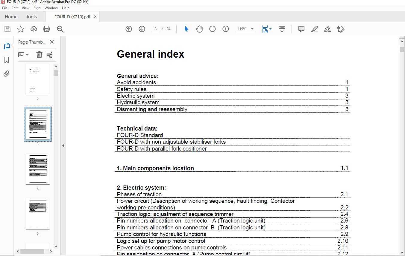
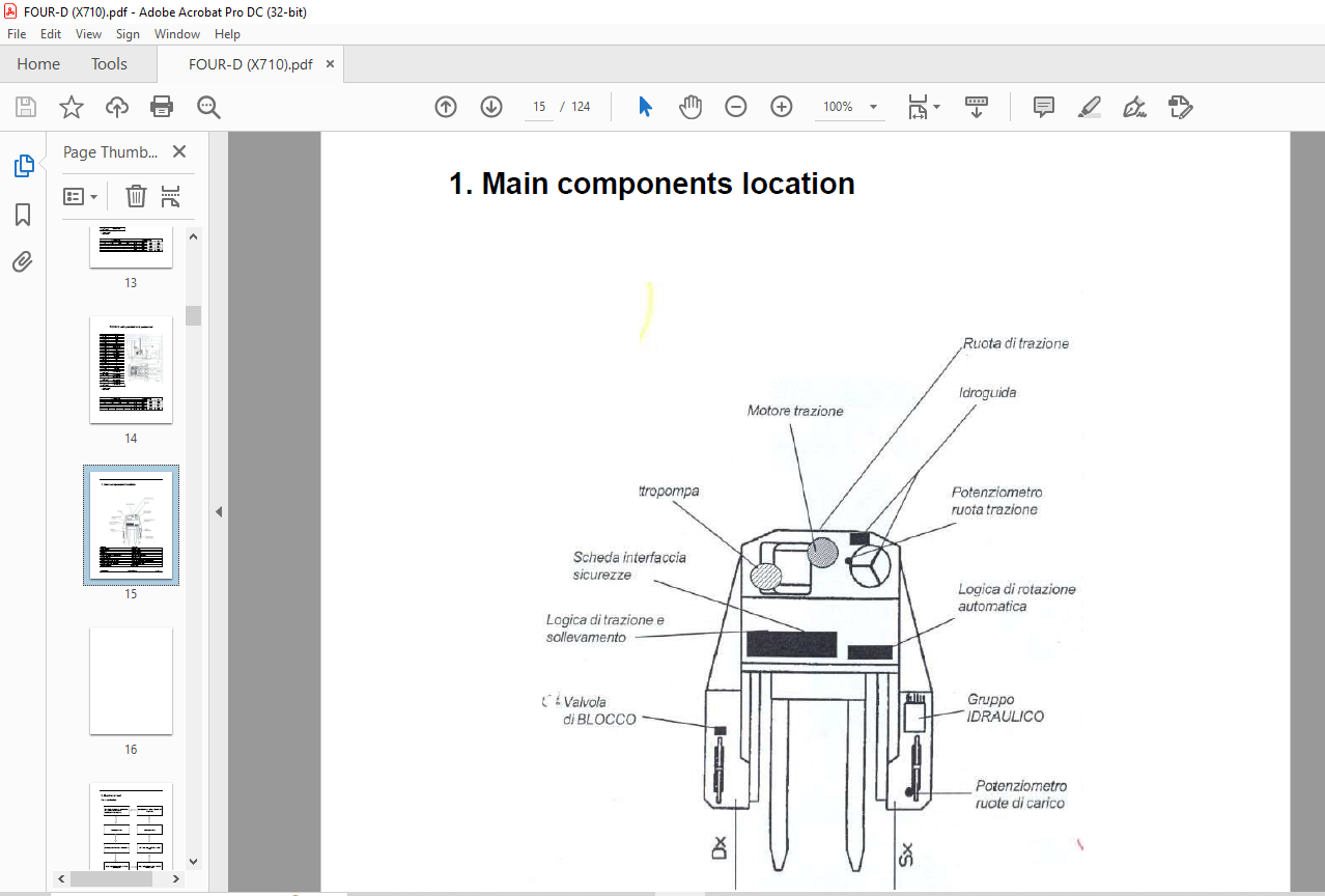
TABLE OF CONTENTS:
OM FOUR-D Series X049 Workshop Manual – PDF DOWNLOAD
General advice:
Avoid accidents 1
Safety rules 1
Electric system 3
Hydraulic system 3
Dismantling and reassembly 3
Technical data:
FOUR-D Standard
FOUR-D with non adjustable stabiliser forks
FOUR-D with parallel fork positioner
1. Main components location 1.1
2. Electric system:
Phases of traction 2.1
Power circuit (Description of working sequence, Fault finding, Contactor
working pre-conditions) 2.2
Traction logic: adjustment of sequence trimmer 2.4
Pin numbers allocation on connector A (Traction logic unit) 2.6
Pin numbers allocation on connector B (Traction logic unit) 2.8
Pump control for hydraulic functions 2.9
Logic set up for pump motor control 2.10
Power cables connections on pump controls 2.11
Pin assignation on connector A (Pump control circuit) 2.12
Pin assignation on connector B (Pump control circuit) 2.13
Interface card, code 82006016 2.14
Input/outputs on interface card 2.15
Warning light panel 2.16
Acceleration electronic transducer 2.17
Delay card for lift lock out with low charge battery 2.18
Electric diagrams:
82006106 Electric diagrams for traction, hydraulic and auxiliary circuits
List of components on diagram circuit code 82006106 2.27
83223207 General wiring diagram
Rev. 07/2005 Cod. 60424201 Page II
3. Steering system:
Definition of steering system 3.1
Manual drive mode 3.2
Automatic drive mode 3.3
Condition of solenoid valves during automatic movement of wheels 3.4
Solenoid Valves Status during the sequence of the 4 phases of automatic wheel
alignment 3.8
Solenoid valves group for wheel rotation code 83207027 valve numbers and positions 3.9
Solenoid valves group for wheel rotation code 95319548 valve numbers and positions 3.10
Steering – Initial checks and settings 3.11
Set up and commissioning wheel movement system 3.12
Power supply and safety card. Code 83223204 3.12
Card 83223204 inputs/outputs 3.13
Position and description of components on card 83223201 fro electric setting and
wheels rotation 3.14
Set up procedure of wheel rotation movement card 3.15
Setting up the rear wheel (traction) rotation 3.17
Set up procedure of front wheel rotation movement card (LOAD WHEELS) 3.20
Summary of Voltage points on trimmers TP1 and TP4 at the end of setting procedure 3.23
Operations to be carried out at the end of setting procedures 3.23
Checking the automatic alignment 3.24
Electric diagrams:
83223202 Electric wiring diagram for wheel rotation code 83223201
83223205 Electric wiring diagram for wheel rotation code 83223204
83223214 Test list
83223215 Functions block diagram
4. Hydraulic system:
Hydraulic group cod. 83207027: Location and description of functions 4.1
Hydraulic group cod. 83207027: Hoses colours and connecting ports 4.2
Table code 83205399 (C) – Hydraulic working circuit
Hydraulic group cod. 95319548: Mounting points and removal instructions 4.3
Hydraulic group cod. 95319548: Eye bolt to lift valve group 4.4
Hydraulic group cod. 95319548: Tube colours and connection ports 4.6
Table code. 83205399 (D) – Hydraulic circuit diagram
Rev. 07/2005 Cod. 60424201 Page III
5. Mechanical parts:
Loading wheel rotating cylinder assembly and disassembly 5.1
Upright bottom truck assembly and disassembly 5.2
Center lifting cylinder assembly and disassembly 5.3
Traverse cylinder assembly and disassembly 5.4
Fork holder plate assembly and disassembly 5.5
Fork holder truck assembly and disassembly 5.6
Decomposition of lifting column 5.7
Loading wheel support assembly and disassembly 5.9
Motor-driven pump assembly and disassembly 5.10
Brake pump assembly anddisassembly 5.11
Wheel operating unit assembly and disassembly 5.12
Loading wheel disassembly and assembly 5.13
Reduction unit disassembly and assembly 5.14
Disassembling the upright 5.16
Assembling the upright 5.17
Drive motor brake adjustment 5.18
Loading wheel brake adjustment 5.19
Air bleeding from the braking plant 5.20
Steering wheel hydraulic unit disassembly
VIDEO PREVIEW OF THE MANUAL:
PLEASE NOTE:
- This is the SAME MANUAL used by the dealerships to diagnose your vehicle
- No waiting for couriers / posts as this is a PDF manual and you can download it within 2 minutes time once you make the payment.
- Your payment is all safe and the delivery of the manual is INSTANT – You will be taken to the DOWNLOAD PAGE.
- So have no hesitations whatsoever and write to us about any queries you may have : heydownloadss @gmail.com
S.M


