

OM CN (4525), CNS (4527), CNi (4528) Workshop Manual – PDF DOWNLOAD
FILE DETAILS:
OM CN (4525), CNS (4527), CNi (4528) Workshop Manual – PDF DOWNLOAD
Language : English
Pages : 170
Downloadable : Yes
File Type : PDF
DESCRIPTION:
OM CN (4525) CNS (4527) CNi (4528) Workshop Manual – PDF DOWNLOAD
From Serial No. F24525S00234
From Serial No. F24527S00015
From Serial No. F24528S00085
Safety Precautions
General
Carefully follow all maintenance and repair procedures.
- Never perform any cleaning, lubrication or maintenance operation when the battery is connected, unless otherwise prescribed. Do not wear rings, wrist-watches, loosen or unlaced garments, such as, for instance, ties, torn clothes, scarves, unbuttoned jackets or unzipped sweaters that may get entangled in moving parts.
- We recommend, instead, to use clothing items that are approved for accidentprevention purposes, for instance: hard hats, nonslip shoes, gloves, safety goggles. Never perform any maintenance operation on the equipment when the operator is sitting on its seat, unless in the event of skilful operators cooperating with the operation to be performed.
- Never operate the machine nor use its equipment from a position other than the proper driving position. Make sure that there is no more pressure in hydraulic circuits before removing either plugs or covers. Please refer to the instructions supplied on the subject in this manual. All maintenance operations should be carried out with the utmost care and attention.
- All service stairs and platforms, which are used in the workshop or on site should be built in compliance with accident-prevention standards in force. Label all controls to indicate that an operation is in progress. Lock the machine and any other equipment that is to be lifted.
- Do not check nor top up the battery while smoking, as concerned fluids are inflammable. Brakes are non-working, when they are manually released in case of maintenance operations: in these cases, it is necessary to keep on controlling the equipment through proper locking or similar devices. In order to transport a damaged equipment, use a tow or a trailer with lowered full load, if available.
- In order to load or unload the equipment on/from a means of transport, prefer a flat area offering a firm support to the wheels of the trailer or truck. Firmly fasten the equipment to the loading platform of the truck or of the trailer and lock its wheels. As for electric heaters, battery chargers and similar devices, use only current auxiliary power supply sources with a good earth connection so as to avoid any electric shock.
- If you should lift or transport heavy parts, use hoists and similar devices having a suitable capacity and keep at a distance all close-by persons. Watch out at all close-by persons. Never use petrol, gas oil or other inflammable fluids, such as detergents; use instead noninflammable and non-toxic commercial solvents. When using compressed air to clean small parts, protect your eyes with side-protected goggles.
- Limit the pressure to the maximum value set out according to local and national rules in force. Do not smoke, do not use naked flames and do not cause sparks in the surrounding area, when you are handling easily flammable materials. Do not use flames as lighting means, when you are performing an operation and you are looking for “leakages” from the equipment.
- Leave all guards at their proper place when the equipment is working. Do not leave the equipment unattended when its members are moving. Do not leave the driving position, if you have not previously applied the hand brake. Remove the start-up key. If a member is jammed, release it only when the motor is stopped.
IMAGES PREVIEW OF THE MANUAL:
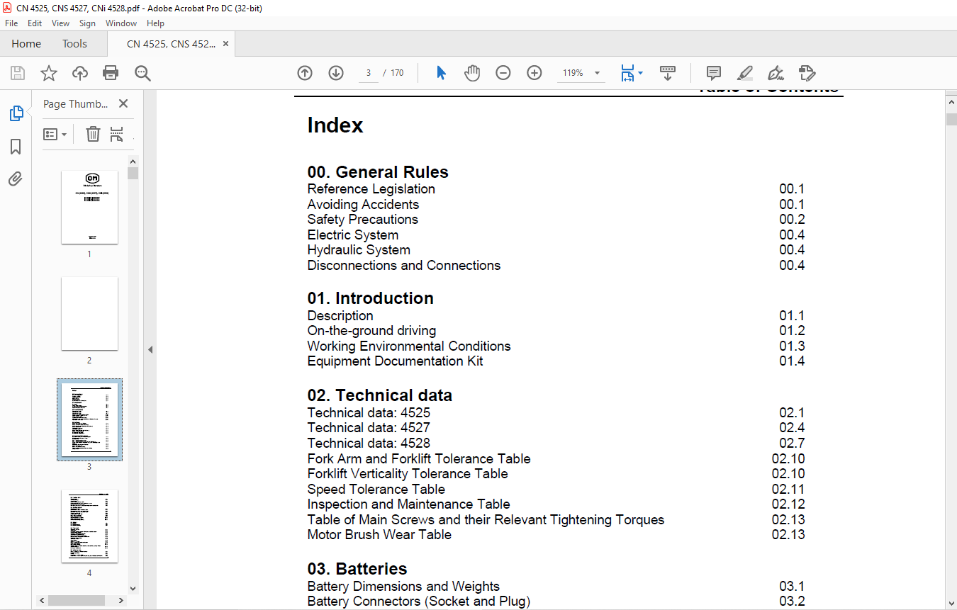
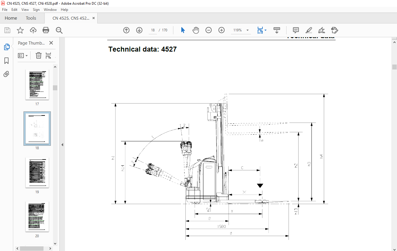
TABLE OF CONTENTS:
OM CN (4525), CNS (4527), CNi (4528) Workshop Manual – PDF DOWNLOAD
Index
00. General Rules
Reference Legislation 00.1
Avoiding Accidents 00.1
Safety Precautions 00.2
Electric System 00.4
Hydraulic System 00.4
Disconnections and Connections 00.4
01. Introduction
Description 01.1
On-the-ground driving 01.2
Working Environmental Conditions 01.3
Equipment Documentation Kit 01.4
02. Technical data
Technical data: 4525 02.1
Technical data: 4527 02.4
Technical data: 4528 02.7
Fork Arm and Forklift Tolerance Table 02.10
Forklift Verticality Tolerance Table 02.10
Speed Tolerance Table 02.11
Inspection and Maintenance Table 02.12
Table of Main Screws and their Relevant Tightening Torques 02.13
Motor Brush Wear Table 02.13
03. Batteries
Battery Dimensions and Weights 03.1
Battery Connectors (Socket and Plug) 03.2
Additional Socket Kit for Double Shifts (Optional) 03.2
Battery replacement 03.2
Vertical battery removal 03.2
Side battery removal 03.3
Battery Fixed / Movable Rack (Optional) 03.4
Built-in Rectifier (Optional) 03.5
Rectifier code 452218501 03.5
Rectifier code 45223531001 03.8
04. Equipment Main Casing
Dashboard – Controls – Instrument System 04.1
Mushroom-Head Emergency Button 04.1
Start-up Switch 04.1
I.B.S. + Hour Counter Instrument 04.2
I.B.S. + Hour Counter Instrument code 7917294030 / 31 04.3
Access Compartment to the Battery Charger Power Supply Cable
(Optional) 04.5
Motor Compartment Bonnet Removal 04.5
Battery Cover Removal 04.7
Bonnet and Cover Assembling 04.7
Position of the identification plates and stickers 04.8
Safety devices 04.9
05. Traction Unit
Traction Speed 05.1
Traction Stoppage 05.1
Traction Motor 05.1
Overhaul of reduction gear unit 05.2
Assembly diagram with relative tightening torques 05.7
Reduction gears code 95325191 05.8
Reduction gears code 45202600200 in replacement of 95325191 05.8
06. Braking System
Electromagnetic Brake 06.1
Electromagnetic Brake Calibration Table 06.1
Electromagnetic Brake code 45205000600 06.2
Description of the Electromagnetic Brake 06.4
Tools to use for E.M.B. 06.5
Assembly of the Clutch Disk 06.6
Brake Flange Assembling 06.6
E.M.B. Assembling Steps 06.7
Rubber Protection Assembling 06.10
E.M.B. Assembling diagram 06.11
Electric (Regenerating) Braking 06.11
07. Rollers
Load Rollers 07.1
Load Roller Removing 07.2
Load Roller Assembling 07.4
08. Tiller Unit
Tiller Head Controls 08.1
Tiller Casing 08.1
Connection Diagram between Tiller Card and COMBI System 08.2
Traction Control Butterfly 08.3
Traction Accelerator Potentiometer 08.3
The Redundant Potentiometer 08.4
Lifting and Lowering Control Butterfly 08.4
Lifting/Lowering “Accelerator” Potentiometer 08.5
Tiller Safety Device Button 08.5
Tiller Head Buttons 08.5
Tiller Positions 08.6
Tiller head assembly 08.7
Lifting / Lowering potentiometer diagram 08.9
Tiller function diagram 08.11
Drive control assembly 08.12
Tiller arm button connection diagram for drive control assembly without
serial transmission 08.15
Horn code 7918915335 08.16
09. Lifting System
Lifting , Lowering and Interlock Devices 09.1
Hydraulic Unit Motor 09.1
Hoister 09.1
Control Unit: 2,2 KW e 3 KW 09.2
Dwgs for the 24v 2.2kw pre-modification and post-modification control units 09.5
Table of Contents
III
Dwgs for the 24v 3kw pre-modification and post-modification control units 09.7
Oil tank with modified breather pipe 09.9
Non-return valve with replaceable cartridge 09.10
Instructions for replacing the non-return valve 09.11
Test To make sure that the pressure relief valve is calibrated correctly 09.13
4525 – 4527 hydraulic circuit 09.14
4528 hydraulic circuit 09.15
Hydraulic Unit and Tank Removal 09.16
10. Wheels
Driving Wheel 10.1
Slick Tyre Driving Wheel Model (Optional) 10.1
Traction Wheel Replacement 10.1
Pivoting wheel unit 10.3
Complete pivoting wheel assembly (lateral view) 10.3
Complete pivoting wheel assembly (front view) 10.4
Wheel Assembly 10.5
Pivoting Wheel Removal 10.6
11. Lubrication
Oil and Grease Supply for the Standard Version 11.1
Oil and Grease Supply for the Cold-Storage Room Version 11.1
General Lubrication 11.1
Greasing of the fifth wheel of the reducer unit 11.2
Topping up of the hydraulic oil 11.2
Lubricant table 11.3
12. COMBI System
COMBI 200 + 300 12.1
Armature Pilot System Diagram 12.2
Field Pilot System Diagram 12.2
Pump Motor Pilot System Diagram 12.4
Energy Regeneration 12.4
COMBI: code 45353605000 12.5
Parameter setting 12.8
COMBI 200 + 300 Diagnostic 12.10
Software 12.10
Description of the PARAMETER menu 12.13
Description of the TESTER menu 12.15
List of alarms 12.18
13. Impianto elettrico
Schema funzionale 13.1
14. Optionals
Tabella riassuntiva 14.1
VIDEO PREVIEW OF THE MANUAL:
PLEASE NOTE:
- This is the SAME exact manual used by your dealers to fix your vehicle.
- The same can be yours in the next 2-3 mins as you will be directed to the download page immediately after paying for the manual.
- Any queries / doubts regarding your purchase, please feel free to contact [email protected]
S.M


