

New Holland L160 and L170 SkidSteer Service Manual
FILE DETAILS:
New Holland L160 and L170 SkidSteer Service Manual
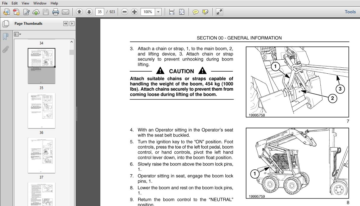
Manual for: L160 and L170
Format: PDF
Print No. 87634734
New Holland L160 and L170 SkidSteer Service Manual : 923Pages
DESCRIPTION:
New Holland L160 and L170 SkidSteer Service Manual
INTRODUCTION:
This service manual provides the technical information needed to properly service and maintain the Models L 160 and L 170 skid steers. Use it in conjunction with the operator’s manual which is supplied with the skid steer. Keep both manuals available for ready reference. The L 160 and L 170 have many similarities with the major differences being engine horsepower and lifting capacity.
- Whenever working on New Holland equipment, left and right sides of the machine are determined by standing behind the unit, looking in the direction of travel. The easiest and least time-consuming removal, disassembly, and reassembly procedures are detailed in the manual.
- Modifying these procedures is not recommended. New Holland skid steers are designed with emphasis on safety for operator protection. However, careless and negligent operation can still result in serious injury to persons or damage to property.
- Be sure to read and follow all safety instructions in this manual. Your New Holland dealer is interested in your obtaining the most from your investment and will be glad to answer any questions you may have about your skid steer. When major service is required, your dealer’s staff of trained service technicians is ready to serve you.
TABLE OF CONTENTS:
New Holland L160 and L170 SkidSteer Service Manual
Section
SECTION 00 – GENERAL INFORMATION
BOOK 1 – 87634735
CONTENTS
Description Page
Introduction 00-2
About Improvements 00-2
Company Policy 00-3
Parts and Accessories 00-3
Model Codes 00-3
Precautionary Statements 00-4
Safety Precaution Information 00-5
General Safety Information 00-7
Machine Model and Serial Number Location 00-9
Engine Model and Serial Number Location 00-9
Hardware Torque Specifications 00-10
Installation of Adjustable Fittings in Straight Thread 0 Ring Bosses 00-12
Standard Torque Data for Hydraulic Tubes and Fittings 00-12
Pipe Thread Fitting Torque 00-13
Lubricants and Coolants 00-13
Sealants 00-13
Properly Support a Raised Machine00-14
Properly Support Boom on Boom Lock Pins00-14
Raising Boom Without Hydraulic Oil Flow 00-14
Raising Boom Without Battery Voltage (12V) 00-16
Reattaching Cylinders After Repair with Boom Resting on Boom Lock Pins00-17
Major Unit Overhaul00-18
Cab and Boom Tilt Procedure 00-19
Craning the Skid Steer 00-25
Special Tools 00-28
Specifications 00-29
Dimensions 00-35
Cab and Boom Tilt Procedure (Cab Upgrade Machines Only) 00-37
SECTION 10- ENGINE
BOOK 1 – 87634735
Chapter 1 – L 160 – N844, L 170 – N844T
CONTENTS
Description Page
General Engine Information 10-3
General Description 10-3
Engine Component Descriptions 10-3
Engine Model and Serial Number Location 10-5
Turbocharger Lubrication 10-5
Safety Precautions 1 0-6
General Engine Specifications 10-7
Troubleshooting 10-11
L170 – Excessive Oil Consumption 10-15
Specifications – Service Standards 10-17
Torque Specifications 10-21
Engine Components Electrical Diagram 10-22
Engine Removal 10-23
Engine Disassembly Sequence 10-28
Engine Component Maintenance 10-36
Valve Seat 1 0-39
Cylinder Block 10-41
Piston and Piston Rings 10-42
Connecting Rod 10-45
Bearing Holder 10-47
Front Crankshaft Bearing (Bushing) 10-48
Crankshaft 10-50
Flywheel and Ring Gear 10-52
Camshaft Assembly10-52
Camshaft Gear and Bearing Assembly 10-53
Timing Gear 10-54
Oil Pump 10-54
Oil Filter 10-55
Water Pump Assembly and Thermostat Housing 10-55
Thermostat 10-55
Governor 10-57
Governor Operation10-59
Engine Reassembly Sequence 10-61
Crankshaft and Bearing Holder Assembly 10-62
Rear Oil Seal 10-63
Backplate/Flywheel Housing 10-63
Flywheel 10-63
Piston and Connecting Rod 10-64
Oil Intake and Oil Strainer 10-64
Oil Sump 10-64
Dipstick and Tube 10-64
Front Plate 10-64
Idler Gear and Oil Pump Assembly10-66
Timing Gear Case Installation 10-66
Crankshaft Pulley 10-66
Injection Pump Installation 10-66
Adjusting the Fuel Injection Timing 10-67
Spill Timing Procedure 10-68
Reinstallation of Engine into Skid Steer Frame 10-75
How to Operate the Engine After Overhaul 10-77
Cooling System 10-78
Cooling System Operation 10-78
Water Pump Assembly and Thermostat Housing 10-79
Radiator 10-80
Fuel System 10-82
Fuel Specifications 10-82
Diesel Fuel10-82
Diesel Fuel Storage10-82
Fuel System Components 10-83
Fuel Guage 10-84
Cold Start Aid 10-85
Fuel Filter System 10-85
Priming the Fuel System 10-86
Fuel System Testing 10-87
Fuel System Components 10-90
Fuel Injection Timing 10-96
Turbocharger – L 170 N844T Engine 10-101
Turbocharger Removal 10-103
Miscellaneous Engine Electrical 10-116
Shut-off Solenoid 10-117
Special Tools 10-119
Labor Guide 10-120
SECTION 27 – REAR DRIVE AXLE (GEARBOXES)
BOOK 2 – 87634738
Chapter 1 – Gearboxes
CONTENTS
Description Page
General Information 27-2
Specifications 27-4
Troubleshooting 27-5
Testing 27-7
Gearboxes 27-8
Gearbox Removal and Inspection 27-8
Gearbox Disassembly 27-12
Gearbox Parts Inspection 27-13
Gearbox Resassembly 27-14
Gearbox Resinstaliation 27-16
Labor Guide 27-19
SECTION 29 – HYDROSTATIC TRANSMISSION
BOOK 2 – 87634738
Chapter 1 – Neutralizer, Pumps, Motors
CONTENTS
Description Page
General Information 29-3
Operation 29-3
Specifications 29-5
Troubleshooting 29-6
Hydrostatic Drive System Testing 29-8
Hydrostatic System Oil Flow 29-11
Hydrostatic Charge System Pressure Test 29-14
Hydrostatic Pump Case Drain Test29-15
Hydrostatic Pump High Pressure Test 29-18
Hydrostatic Pump Efficiency Test 29-20
Hydrostatic Motor Case Drain Test 29-22
Hydrostatic Motor Efficiency Test 29-23
Hydraulic, Hydrostatic System Air Ingress Test 29-25
Hydrostatic Pumps 29-27
Hydrostatic Pump Removal 29-27
Hydrostatic Pump Disassembly 29-31
Hydrostatic Pump Parts Inspection 29-36
Hydrostatic Pump Reassembly 29-41
Hydraulic System Pump Installation (Without High Flow) 29-47
Hydraulic System Pump/High Flow Pump Installation 29-49
Hydrostatic Pump Reinstallation 29-54
Hydrostatic Motor 29-58
Hydrostatic Motor Removal 29-58
Hydrostatic Motor Disassembly 29-62
Hydrostatic Motor Parts Inspection 29-67
Hydrostatic Motor Reassembly 29-70
Hydrostatic Motor Reinstallation 29-79
Hydraulic System Cleaning Procedure 29-85
Start-up Procedure After Rebuild (After Pump or Motor Replacement) 29-88
Charge Check Valve 29-90
Charge Check Valve Removal and Replacement 29-90
Steering System 29-91
Hydrostatic System Controls 29-91
Neutralizer Assembly 29-93
Left Control Handle With No Boom Hand Control 29-97
Left Control Handle With No Boom Hand Control Removal 29-97
Left Control Handle With No Boom Hand Control Disassembly 29-97
Left Control Handle With No Boom Hand Control Inspection29-98
Left Control Handle With No Boom Hand Control Reassembly 29-98
Left Control Handle With No Boom Hand Control Reinstallation 29-98
Left Control Handle With Boom Hand Control 29-100
Left Control Handle With Boom Hand Control Removal 29-100
Left Control Handle With Boom Hand Control Disassembly 29-101
Left Control Handle With Boom Hand Control Inspection 29-102
Left Control Handle With Boom Hand Control Reassembly 29-103
Left Control Handle With Boom Hand Control Reinstallation 29-104
Right Control Handle With Auxiliary or Bucket Control 29-106
Right Control Handle With Auxiliary or Bucket Control Removal 29-106
Right Control Handle With Auxiliary or Bucket Control Disassembly 29-107
Right Control Handle With Auxiliary or Bucket Control Inspection 29-109
Right Control Handle With Auxiliary or Bucket Control Reassembly 29-110
Right Control Handle With Auxiliary or Bucket Control Reinstallation 29-113
Drive Control Adjustment Procedure 29-115
Neutral Adjustment 29-116
Labor Guide 29-118
Machines Equipped With ISO Pattern Pilot Controls 29-121
Pilot Control Travel System Overview 29-121
Specifications 29-142
Troubleshooting 29-143
Check 1 – Checking the DA Pressure 29-144
Check 2 – Checking Charge Pressure/Flow 29-146
Check 3 – Checking Circuit Relief Valve Pressure 29-147
Pump Adjustments 29-148
Pump Removal 29-149
Pump Installation 29-153
Pump Disassembly 29-156
Pump Assembly 29-173
Pilot Control Travel Lever Removal 29-189
Pilot Control Travel Lever Installation 29-193
Illustration – Hydrostatic System (Machines Equipped With Pilot Controls} 29-195
Procedure to Bleed Air From the Pilot Control Hydraulic System 29-196
SECTION 33 – BRAKES AND CONTROLS
BOOK 2 – 87634738
Chapter 1 – Parking Brake
Contents
Description Page
General Information 33-2
Specifications 33-4
Troubleshooting 33-5
Testing 33-7
Parking Brake 33-8
Parking Brake Removal and Installation 33-9
Labor Guide 33-22
8
Section Description
35000 –
SECTION 35 – HYDRAULIC SYSTEM
BOOK -3 – 87634740
Chapter 1 – Valves, Gear Pump, Cylinders, and Pedal Controls
Contents
Page
General Information 35-3
Hydraulic System Compatibility 35-4
Boom Cylinder PivotPins 35-6
Boom Cylinder Pivot Pin Location and MachineUsage 35-6
Control Valve PowerBe¥ond 35-7
Specifications 35-8
Troubleshooting 35-12
Auxiliary Boom Hydraulics Troubleshooting 35-16
Hydraulic System Testing 35-18
Hydraulic System OiJflow 35-24
Control Valve – Bucket SpoolShifted 35-25
Control Valve – Boom SpooIShit1ed 35-26
Control Valve – Auxiliary SpoolShitted 35-27
3571002
Main System PressureTests 35-28
Checking Main System Pressure at Boom C¥linders 35-30
Checking Main System Pressure at Bucket Cylinders 35-31
Checking Main System Pressure at Auxiliary Boom Hydraulic Quick Couplers 35-32
Boom Circuit Relief ValveTest 35-33
Gear Pump Flow EfficiencyTesL 35-35
Boom and Bucket Spool Lock SolenoidTest 35-39
Hydraulic, Hydrostatic System Air Ingress:Test 35-41
Control Valve Specificatiors 35-43
3572450
Control Valve Removal 35-44
Control Valve Disassembly and Inspection 35-45
Control Valve Parts Inspection 35-49
Control Valve Reassembly 35-50
Control Valve Reinstallation 35-53
Hydraulic Pump Specifications 35-54
3571010
Hydraulic Pump Removal 35-55
3571020
Hydraulic Pump Removal/Disassembly (Without HighElow) 35-56
High Flow Pump Parts Inspection 35-58
Hydraulic Pump Parts Inspection 35-59
Hydraulic Pump Reassembly/Installation (Without HighFlow) 35-61
Hydraulic Pump and High Flow Pump Reassembly/Installation 35-64
New Hydraulic Pump Installation (Without HighFlow) 35-70
New Hydraulic Pump/High Flow Pump Installation 35-72
Gear Pump Start-up Procedure 35-78
Cylinders, Boom andBucket 35-79
3571010
Boom Cylinder Removal 35-81
3573018
Boom Cylinder Disassembl¥ 35-83
Boom Cylinder Parts Inspection 35-84
Boom Cylinder Reassembl¥ 35-85
Boom Cylinder Reinstallation 35-87
9
3573010
Bucket Cylinder RemovaJ 35-87
3573013
Bucket Cylinder Disassembly 35-88
Bucket Cylinder Parts Inspection 35-89
Bucket Cylinder Reassembly 35-90
Bucket Cylinder Reinstallation 35-92
Pedal Controls 35-93
3572416
Pedal Removal (With Boom and Bucket Pedal Controls) 35-93
Pedal Inspection (With Boom and Bucket Pedal Controls 35-93
Pedal Reinstallation (With Boom and Bucket Pedal Controls 35-95
3572416
Pedal Removal (With Boom and Bucket Hand Controls 35-98
Pedal Inspection (With Boom and Bucket Hand Coni:rols 35-99
Pedal Reinstallation (With Boom and Bucket Hand Contrals 35-100
35300
Hydraulic Cooling, Filter, Reservoir System 35-103
FilterS¥stem 35-104
Filter RernovaJ 35-104
3570505
Base Removal 35-104
Reassembly 35-105
OiJCooler 35-105
3530010
Oil Cooler RemovaJ 35-105
Oil Cooler Reassembly 35-106
35300
Oil Reservoir 35-106
3530010
Oil Reservoir Flemoyal 35-107
Oil Reservoir Reinstallation 35-108
Adapting Attachments 35-109
LaborGuide 35-110
Machines Equipped With Pilot Controls
Specifications 35-111
Loader Function Troubleshooting 35-112
Pilot Pressure:rest 35-113
Illustration – Loader ControJ 35-114
Right Control Handle – Remo\(al 35-115
Right Control Handle – Installation 35-118
HydrauliC Schematic – Frame 3 – (Mechanical Control Machines) 35-120
HydrauliC Schematic – Frame 4- (Mechanical Control Machines) 35-121
HydrauliC Schematic – Frame 5- (Pilot Control Machines) 35-122
HydrauliC Schematic – Frame 6- (Pilot Control Machines) 35-123
HydrauliC Schematic – Frame 7- (Pilot Control Machines) 35-124
HydrauliC Schematic – Frame 8- (Pilot Control Machines) 35-125
Hydraulic Schematic – Frame 9- (Pilot Control Machines) 35-126
10
SECTION 37 – TOWING HOOKS AND BALLASTING
BOOK 3 – 87634740
Chapter 1 – Rear Counterweights
CONTENTS
Section Description Page
37 140 10 Rear Counterweights 37-2
37 140 12 Rear Counterweight Support Removal 37-2
Section
90 152 46
SECTION 39 – FRAMES
BOOK 3 – 87634740
Chapter 1 – Lower Main, ROPS
CONTENTS
Description Page
General Information 39-2
ROPS 39-2
ROPS Frame 39-2
ROPS Removal 39-2
ROPS Reinstallation 39-8
Labor Guide 39-11
ROPS Removal (Cab Upgrade Machines Only) 39-12
ROPS Installation (Cab Upgrade Machines Only) 39-24
Description
SECTION 44 – AXLES AND WHEELS
BOOK 3 – 87634740
Chapter 1 – Axles
CONTENTS
Page
General Information 44-2
Specifications 44-4
Troubleshooting 44-5
Testing 44-7
Axles 44-8
Axle Housing Assembly Removal 44-8
Axle Disassembly 44-9
Axle Parts Inspection 44-11
Axle Reassembly 44-12
Axle Housing Reinstallation 44-14
Final Drive 44-15
Drive Chain and Sprocket Removal 44-15
Final Drive Parts Inspection 44-19
Final Drive Reassembly 44-20
TireslWheels 44-22
Tire and Track Installation 44-23
Labor Guide 44-24
12
Section
50100
SECTION 50 – CAB CLIMATE CONTROL
CHAPTER 1 – HEATERIDEF ROSTER/AIR CONDITIONER
Book 3 – 87634740
CONTENTS
Description Page
Heater/Defroster (Cab) 50-2
Labor Guide 50-8
Air Conditioning System Special Tools 50-9
Air Conditioning System General Specifications 50-11
Air Conditioning System Discharging and Evacuate and Recovery 50-13
Air Condit ioning System Charging 50-19
Compressor RemovaL 50-21
Compressor Installation 50-23
Compressor Oil Level Check 50-25
Compressor Belt Measure and Tension Adjust 50-28
Compressor Magnetic Clutch Disassemble 50-29
Compressor Magnetic Clutch Assembly 50-37
Air Conditioning System RemovaL 50-43
Air Condit ioning System Installation 50-45
Air Conditioning System Condenser RemovaL _ 50-46
Air Conditioning System Condenser Installation ___ 50-47
Air Conditioning System Evaporator RemovaL _ 50-48
Air Conditioning System Evaporator Installation ___ 50-49
Receiver/Drier Removal and Installation _ 50-51
Air Conditioning System Visual Inspection and Troubleshooting 50-53
Air Conditming System Testing 50-54
Air Conditioning System Leakage Test 50-55
Air Condition ing System Problem Solving 50-56
Air Condition ing System Problem Solving 50-57
13
SECTION 55 – ELECTRICAL SYSTEM
Chapter 1 – Instrument Cluster, Circuits, Alternator, and Starter
Book 4 – 87634741
Section
55 000
Contents
Description Page
General Electrical Information 55- 4
Definition of Terms 55-5
Adapting Attachments Requiring 12V Electrical Power 55-7
Specifications 55-8
Wire Identification and Circuit Diagram Legend 55-12
Electrical Diagram – Starting System 55-13
Electrical Diagram – Power Distribution 55-14
Electrical Diagram -Safety Interlock and Fuel Supply System 55-15
Electrical Diagram – Instrument Cluster Monitoring System 55-16
Electrical Diagram – Standard Lamps 55-17
Electrical Diagram – Loader Arm Auxiliary Electrical Control Box (Optional) 55-18
Electrical Diagram – Loader Arm Auxiliary Electric Power Controls (Optional) 55-19
Electrical Diagram – Flasher and Turn Signals North America Electrical 55-20
Electrical Diagram – Main Electrical European On-Road Regulations 55-21
Electrical Diagram – Boom/Rear Electrical European On-Road Regulations 55-22
Electrical Diagram – Right-Hand Handle (Option) Electrical Multifunction Adaptation 55-23
Electrical Diagram – Left-Hand Handle (Options) 55-24
Electrical Diagram – Right-Hand Handle (Options) 55-25
Electrical Diagram – Glow Plugs 55-26
Electrical Diagram – Rotating Beacon (Optional) 55-27
Electrical Diagram – Two Speed (Optional) 55-28
Electrical Diagram – Horn (Optional) 55-29
Electrical Diagram – Accessory Outlet (Optional) 55-30
Electrical Diagram – Back-up Alarm (Optional) 55-31
Electrical Diagram – WiperlWasher (Optional) 55-32
Electrical Diagram – Auxiliary Hydraulics (Optional) 55-33
Electrical Diagram – High Flow (Optional) 55-34
Electrical Diagram – Hydraulic Coupler (Optional) 55-35
Electrical Diagram – Heating and Air Conditioning (Optional) 55-36
Electrical Diagram – Pilot Hydraulic Controls 55-37
Electrical Diagram – Ground Connections 55-38
Electrical Diagram – Ground Connections 55-39
Wire Identification and Circuit Diagram Legend (Cab Upgrade Machines) 55-40
Electrical Diagram – Starting System (Cab Upgrade Machines) 55-41
Electrical Diagram – Power Distribution (Cab Upgrade Machines) 55-42
Electrical Diagram -Safety Interlock and Fuel Supply System (Cab Upgrade Machines) 55-43
Electrical Diagram – Instrument Cluster Monitoring System (Cab Upgrade Machines) 55-44
Electrical Diagram – Standard Lamps (Cab Upgrade Machines) 55-45
Electrical Diagram – Loader Arm Auxiliary Electrical Control Box (Optional)
(Cab Upgrade Machines) 55-46
Electrical Diagram – Loader Arm Auxiliary Electric Power Controls (Optional)
(Cab Upgrade Machines) 55-47
SECTION 55 – ELECTRICAL SYSTEM
Electrical Diagram – Flasher and Turn Signals North America Electrical
(Cab Upgrade Machines) 55-48
Electrical Diagram – Main Electrical European On-Road Regulations
(Cab Upgrade Machines) 55-49
Electrical Diagram – Boom/Rear Electrical European On-Road Regulations
(Cab Upgrade Machines) 55-50
Electrical Diagram – Work Lamps (Cab Upgrade Machines) 55-51
Electrical Diagram – Control Lever Interface (Cab Upgrade Machines) 55-52
Electrical Diagram – Left-Hand Handle (Options) (Cab Upgrade Machines) 55-53
Electrical Diagram – Right-Hand Handle (Options) (Cab Upgrade Machines) 55-54
Electrical Diagram – Grid Heater System (Cab Upgrade Machines) 55-55
Electrical Diagram – Rotating Beacon (Optional) (Cab Upgrade Machines) 55-56
Electrical Diagram – Two Speed (Optional) (Cab Upgrade Machines) 55-57
Electrical Diagram – Horn (Optional) (Cab Upgrade Machines) 55-58
Electrical Diagram – Accessory Outlet (Optional) (Cab Upgrade Machines) 55-59
Electrical Diagram – Back-up Alarm (Optional) (Cab Upgrade Machines) 55-60
Electrical Diagram – Wiper/Washer/Door Switch (Optional) (Cab Upgrade Machines) 55-61
Electrical Diagram – Auxiliary Hydraulics (Optional) (Cab Upgrade Machines) 55-62
Electrical Diagram – High Flow (Optional) (Cab Upgrade Machines) 55-63
Electrical Diagram – Hydraulic Mount Plate (Optional) (Cab Upgrade Machines) 55-64
Electrical Diagram – Heating and Air Conditioning (Optional) (Cab Upgrade Machines) 55-65
Electrical Diagram – Pilot Hydraulic Controls 55-66
Electrical Diagram – Ground Connections (Cab Upgrade Machines) 55-67
Electronic Instrument Cluster (EIC) Panel 55-68
Electronic Instrument Cluster (EIC) Panel (Cab Upgrade Machines) 55-69
Electronic Instrument Cluster Operating Instructions 55-70
Electronic Instrument Cluster Troubleshooting 55-73
Advanced Instrument Cluster (AIC) Panel (Optional) 55-77
Advanced Instrument Cluster (AIC) Panel (Optional) (Cab Upgrade Machines) 55-78
Advanced Instrument Cluster Operating Instructions 55-79
Advanced Instrument Cluster Troubleshooting 55-86
Removal, Installation and Wiring of Electrical Components 55-90
Battery Removal and Installation 55-91
Cab Fuse Block and Panel Removal and Installation 55-92
Seat Switch Removal 55-93
Seat Switch Installation 55-94
Seat Belt Buckle and Switch Assembly Removal and Installation 55-94
Road Light and Work Light Switch Removal and Installation 55-95
Engine Fuse and Relay Panel 55-96
Start Interlock Relay Removal and Installation 55-97
Engine Fuse Block Removal and Installation 55-98
Preheat Relay Removal and Installation 55-99
Preheat Glow Plug Removal and Installation 55-100
Fuel System Components 55-101
Electric Fuel Pump 55-102
Electric Fuel Pump Removal 55-104
SECTION 55 – ELECTRICAL SYSTEM
Fuel Shutoff Solenoid 55-104
Fuel Shutoff Solenoid Testing 55-104
Replacement of Fuel Shutoff Solenoid 55-105
Air Filter Restriction Indicator Switch Removal and Installation 55-106
Engine Coolant Temperature Sender Removal and Installation 55-106
Engine Oil Pressure Switch Removal and Installation 55-107
Hydrostatic Charge Pressure Switch Removal and Installation 55-107
Hydraulic Oil Filter Restriction Switch Removal and Installation 55-108
Hydraulic Oil Temperature Sender Removal 55-108
Hydraulic Oil Temperature Sender Installation 55-109
Boom/Bucket Control Valve Spool Lock Solenoid Removal and Installation 55-110
Road/Work Lights 55-111
Alternator (55 Amp Version) 55-114
Alternator Service Specifications 55-116
Alternator – System Testing and Troubleshooting 55-117
Initial Tests 55-120
Alternator Removal 55-125
Alternator Disassembly 55-126
Alternator Installation 55-132
Starter 55-133
Starter Motor Troubleshooting 55-134
Starter Motor Removal 55-135
Starter Motor Disassembly 55-140
Starter Motor Inspection and Repair 55-144
Starter Motor Reassembly 55-150
Starter Motor Installation 55-153
Miscellaneous Engine Components 55-154
Glow Plugs and Glow Plug Troubleshooting 55-154
Oil Pressure Switch 55-155
Fuel Shutoff Solenoid 55-155
Labor Guide 55-156
16
SECTION 82 – FRONT LOADER (BOOM AND MOUNTING PLATE)
BOOK 4 – 87634741
Chapter 1 – Buckets
CONTENTS
Description Page
General Information 82-2
Buckets 82-2
Boom Lock Pins and Linkage 82-3
Boom 82-3
Attachment Mounting Plate 82-4
Boom and Cylinder Pivot Pins 82-4
Boom and Cylinder Pivot Pin Location and Machine Usage 82-4
Boom and Cylinder Pivot Pins Size 82-5
Pallet Fork 82-6
Utility Fork 82-7
Bucket Cutting Edge (Replacement) 82-8
Bucket Latch Plate Installation Procedure 82-9
Dirt Tooth Kit Installation 82-11
Bucket Tooth Spacing 82-13
Boom Lock Pin/Linkage 82-15
Boom Lock Pin/Linkage Removal 82-15
Boom Lock Pin/Linkage Reinstallation 82-16
Boom, Upper and Lower Link 82-18
Boom, Upper and Lower Link Removal 82-18
Front Boom Mounting Plate Pivot Hub Replacement 82-24
Boom, Upper and Lower Link Reinstallation 82-25
Attachment Mounting Plate82-29
Attachment Mounting Plate Removal 82-29
Repair/Rebuild Mounting Plate 82-30
Latch Lever and Pin Removal/Repair 82-30
Attachment Mounting Plate Parts Inspection 82-32
Checking Procedure for Buckets and Attachments 82-36
Checking Procedure 82-38
Checking the Loader Faceplate 82-39
Labor Guide 82-41
SECTION 88 – ACCESSORIES
BOOK 4 – 87634741
Chapter 1 – Dealer Installed Options
CONTENTS
Description Page
General Information 88-2
Adapting Attachments Requiring 12V Electrical Power 88-2
Hydraulic System Compatibility 88-5
Arm Pads For Cab Side Panels 88-7
Armrests for Deluxe Seat 88-7
Forearm Rests 88-8
Back-up Alarm 88-9
Block Heater (Engine) 88-10
Electric Power Supply (12 Volt, 15 Amp) 88-11
Exhaust (Engine) 88-12
Aspirator Precleaner Muffler 88-12
High Flow Hydraulics 88-14
High Flow Hydraulics Troubleshooting 88-16
High Flow Hydraulics Component Replacement 88-18
Horn 88-25
Shoulder Belt (Seat)88-26
Slow-moving Vehicle (SMV) Sign Kit 88-27
Warning Light (Rotary Beacon) 88-28
Warning Lights (Four-way FlashersfTurn Signal/Horn) 88-31
Labor Guide 88-35
18
Chapter 1 – Cab and Seat
CONTENTS
Description Page
General Information 90-2
Seat and Seat Pan Support 90-2
Cab Inner Shell 90-3
Seat Removal 90-3
Seat Pan Support Removal 90-3
Seat, Switch and Pan Reinstallation 90-5
Cab Inner Shell 90-7
Cab Inner Shell Removal 90-7
Cab Inner Shell Reinstallation 90-14
Safety Decals 90-22
Labor Guide 90-26
VIDEO PREVIEW OF THE MANUAL:

IMAGES PREVIEW OF THE MANUAL:

PLEASE NOTE:
- This is the SAME MANUAL used by the dealerships to diagnose your vehicle
- No waiting for couriers / posts as this is a PDF manual and you can download it within 2 minutes time once you make the payment.
- Your payment is all safe and the delivery of the manual is INSTANT – You will be taken to the DOWNLOAD PAGE.
- So have no hesitations whatsoever and write to us about any queries you may have : heydownloadss @gmail.com


