MTU Marine Application Technical Project Guide Manual PDF DOWNLOAD
$28.95
MTU Marine Application Technical Project Guide Manual PDF DOWNLOAD
Description
MTU Marine Application Technical Project Guide Manual PDF DOWNLOAD
FILE DETAILS:
MTU Marine Application Technical Project Guide Manual PDF DOWNLOAD
Language :English
Pages :230
Downloadable : Yes
File Type : PDF
IMAGES PREVIEW OF THE MANUAL:
TABLE OF CONTENTS:
MTU Marine Application Technical Project Guide Manual PDF DOWNLOAD
I TABLE OF CONTENTS
Chapter Title Page
I INTRODUCTION I
II TABLE OF CONTENTS V
III LIST OF FIGURES XI
1 GENERAL 1-1
1.1 Designations 1-1
2 DEFINITION OF APPLICATION GROUPS 2-1
2.1 General Notes 2-1
2.2 Marine Main Propulsion and Auxiliary Propulsion Plants 2-2
2.3 On-Board Electric Power Generation/Auxiliary Power 2-3
3 SPECIFICATION OF POWER AND REFERENCE CONDITION 3-1
3.1 Definition of Terms 3-1
3.1.1 ISO Standard Fuel-Stop Power (ICFN) 3-1
3.1.2 ISO Standard Power Exceedable by 10 % (ICXN) 3-2
3.2 Reference Conditions 3-2
3.3 Intake Air (Quality) 3-3
3.4 Intake and Exhaust Pressure Loss 3-3
3.4.1 General 3-3
3.5 Inclination 3-5
3.6 Load Profile 3-6
3.7 Time Between Major Overhauls (TBO) 3-9
4 FLUIDS AND LUBRICANTS SPECIFICATION 4-1
4.1 General Notes 4-1
4.2 Approved Fuel for MTU Engines 4-1
4.2.1 Requirements 4-1
4.2.2 Low Sulphur Diesel Fuels 4-2
4.2.3 Diesel Fuels in Winter Operation 4-2
4.2.4 Fuel Properties for Calculation Routines 4-2
5 DIESEL ENGINE PERFORMANCE DIAGRAM 5-1
5.1 General Notes 5-1
5.2 Load Curves 5-7
Technical Project Guide
Marine Application
Page VI
Table of Contents
TPG-General.doc 04.2004 © MTU
Rev. 2.01
Chapter Title Page
6 PROPULSION, INTERACTION DIESEL ENGINE WITH APPLICATION 6-1
6.1 Propulsor 6-1
6.1.1 Abbreviations 6-1
6.1.2 Propulsive Devices (Overview) 6-3
6.1.2.1 General characteristics 6-3
6.1.2.2 Typical arrangements 6-5
6.1.2.3 Manoeuvring characteristics 6-7
6.1.3 Shaft Line and Gearbox Losses 6-9
6.2 Propeller 6-10
6.2.1 Propeller Geometry 6-10
6.2.2 Propeller Type Selection 6-12
6.2.2.1 FPP or CPP 6-12
6.2.2.2 Propeller size 6-13
6.2.2.3 Cavitation and thrust breakdown 6-13
6.2.2.4 Propeller for high speed vessels 6-13
6.2.3 Direction of Propeller Rotation 6-14
6.2.4 Selection of Propeller Blade Number 6-17
6.3 Propeller Curve 6-18
6.3.1 Basics 6-18
6.3.2 Theoretical Propeller Curve 6-23
6.3.3 Estimating the Required Diesel Engine Power 6-25
6.4 Propeller and Performance Diagram 6-26
6.4.1 Driving Mode 6-26
6.4.1.1 General applications 6-26
6.4.1.2 Bollard pull 6-28
6.4.2 Fixed Pitch Propeller (FPP) 6-30
6.4.3 Controllable Pitch Propeller (CPP) 6-32
6.5 Waterjet and Performance Diagram 6-38
6.5.1 Geometry and Design Point 6-38
6.5.2 Parallel Operation 6-43
6.5.3 Estimation of Size and Shaft Speed 6-44
6.6 Fuel Consumption 6-45
6.6.1 General Assumptions 6-45
6.6.2 Operating Profile 6-47
6.6.3 Fuel Consumption at Design Condition 6-52
6.6.4 Cruising Range 6-53
6.6.5 Endurance at Sea 6-54
6.6.6 Calculating Examples 6-55
6.6.6.1 Example Data (Series 2000) 6-55
6.6.6.2 Fuel consumption at design condition 6-57
6.6.6.3 Fuel tank volume for a given range 6-58
6.6.6.4 Theoretical cruising range 6-59
6.6.6.5 Annual fuel consumption for an operating profile 6-60
6.6.6.6 Correcting the lower heating value 6-61
6.7 Generator Drive 6-62
Technical Project Guide
Marine Application
Table of Contents Page VII
TPG-General.doc 04.2004 © MTU
Rev. 2.01
Chapter Title Page
7 APPLICATION AND INSTALLATION GUIDELINES 7-1
7.1 Diesel Engine/Gearbox Arrangements 7-1
7.1.1 General notes 7-1
7.1.2 Diesel Engine with Flange-Mounted Gearbox (F-Drive) 7-4
7.1.2.1 General notes 7-4
7.1.3 Diesel Engine with Free-Standing Gearbox, V-Drive Inclusive 7-5
7.1.3.1 General notes 7-5
7.1.4 Diesel Engine with Free-Standing Gearbox, Universal Shaft and V-drive 7-7
7.1.4.1 General notes 7-7
7.2 Foundation 7-8
7.3 Generator Set Arrangement 7-9
7.3.1 General Notes: 7-9
7.3.2 Diesel Engine with Free-Standing Generator 7-10
7.3.3 Diesel Engine with Flange-Mounted Generator 7-11
7.4 System Interfaces and System Integration 7-12
7.4.1 Flexible Connections 7-12
7.4.2 Combustion Air and Cooling/Ventilation Air Supply 7-15
7.4.2.1 General notes 7-15
7.4.2.2 Combustion air intake from engine room 7-16
7.4.2.3 Combustion air intake directly from outside (special application) 7-17
7.4.2.4 Cooling/ventilation air system 7-18
7.4.3 Exhaust System 7-20
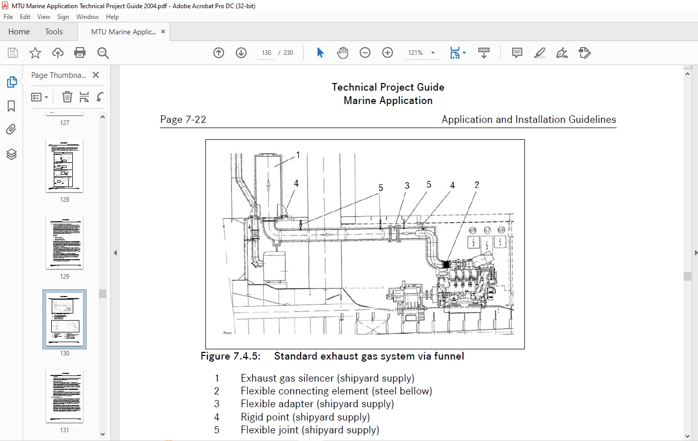
7.4.3.1 Arrangements, support and connection for pipe and silencer 7-21
7.4.3.2 Water-cooled exhaust system 7-23
7.4.4 Cooling Water System 7-25
7.4.4.1 Cooling water system with on-engine mounted heat exchanger 7-26
7.4.4.2 Cooling water system with separately-mounted heat exchanger 7-27
7.4.4.3 Central cooling water system 7-28
7.4.4.4 Sea chest construction for ice ships 7-29
7.4.4.5 Ship heating 7-30
7.4.5 Fuel System 7-31
7.4.5.1 General notes 7-31
7.4.5.2 Design data 7-32
7.4.6 Lube Oil System 7-35
7.4.7 Starting System 7-38
7.4.7.1 Electric starter motor 7-38
7.4.7.2 Compressed-air starting, compressed-air starter motor 7-39
7.4.7.3 Compressed-air starting, air-in-cylinder 7-40
7.4.7.4 Starting aid measures 7-43
7.4.8 Electric Power Supply 7-44
Technical Project Guide
Marine Application
Page VIII
Table of Contents
TPG-General.doc 04.2004 © MTU
Rev. 2.01
Chapter Title Page
7.5 Emission 7-46
7.5.1 Exhaust Gas Emission, General Information 7-46
7.5.2 Acoustical Emission, General Information 7-47
7.5.2.1 Airborne noise level 7-48
7.5.2.2 Exhaust gas noise level 7-50
7.5.2.3 Structure-borne noise level 7-51
7.6 Mechanical Power Transmission 7-58
7.7 Auxiliary Power Take-Off (PTO), Power Take-In (PTI) 7-63
7.7.1 Diesel Engine Mounted PTO 7-63
7.7.2 Gearbox Mounted PTO/PTI 7-64
7.7.2.1 Gearbox shaft mounted auxiliary PTO 7-64
7.7.2.2 Gearbox top mounted PTO or PTI 7-65
7.7.2.3 Diesel engine with free end PTO 7-66
7.8 Torsional Vibration 7-67
8 CLASSIFICATION AND ACCEPTANCE TEST 8-1
8.1 Explanation of Important Classification and Acceptance Terms 8-1
8.1.1 Classification Societies 8-1
8.1.2 Ship Classification 8-1
8.1.3 List of Classification Societies 8-4
8.1.4 Characters of Classification and Notations 8-5
8.1.5 Type Approval/Prototype Test 8-9
8.1.6 Drawing Approval (Design Approval/Design Appraisal) 8-9
8.1.7 Classification Acceptance 8-9
8.1.8 Test run control 8-9
8.1.9 Factory Acceptance Test (FAT) 8-10
8.2 Acceptance Test According to a Classification Society 8-10
8.2.1 Main Diesel Engines for Direct Propeller Drive: 8-10
8.2.2 Main Diesel Engines for Indirect Propeller Drive 8-10
8.2.3 Diesel Engines for Auxiliary and Electric Generator Drives 8-10
8.3 Example Documents 8-11
9 DIESEL ENGINE CONTROL SYSTEM 9-1
9.1 General 9-1
10 SHIP AUTOMATION SYSTEM 10-1
10.1 Pre Configured Automation Systems 10-1
10.1.1 Standard Monitoring and Control for Diesel Engine Series 2000/4000 10-1
10.1.2 BlueLine Monitoring and Control for Diesel Engine Series 2000/4000 10-3
10.1.3 Configuration documents for Monitoring and Control systems 10-5
10.2 Project Specific Ship Automation Systems 10-5
Technical Project Guide
Marine Application
Table of Contents Page IX
TPG-General.doc 04.2004 © MTU
Rev. 2.01
Chapter Title Page
11 MAINTENANCE CONCEPT / MAINTENANCE SCHEDULE 11-1
11.1 Reason for Information 11-1
11.2 Advantages of the Maintenance Concept: 11-1
11.3 Maintenance Schedule: 11-1
11.3.1 Cover Sheet 11-1
11.3.2 Maintenance Schedule Matrix 11-2
11.3.3 Task List 11-6
12 ASSEMBLING INSTRUCTIONS (TRANSPORT, STORAGE, STARTING) 12-1
12.1 Transportation 12-1
12.2 Storage and Starting 12-1
13 INSTALLATION DESCRIPTION 13-1
APPENDIX
A ILLUSTRATION REFERENCES 1
B CONVERSION TABLE 3
C GLOSSARY 9
VIDEO PRVIEW:
https://vimeo.com/859256739?share=copy
DESCRIPTION:
MTU Marine Application Technical Project Guide Manual PDF DOWNLOAD
INTRODUCTION
MTU Friedrichshafen and Detroit Diesel Corporation, two DaimlerChrysler Group companies, have combined their off-highway operations. With products from MTU, DDC, and Mercedes-Benz under one roof, a world-leading supplier of power systems for the marine, rail, power generation, and agricultural & construction machinery sectors has been created.
Especially within the marine sector, the company has established a long and successful partnership with hundreds of thousands of diesel engines in operation around the globe on all the seas. All diesel engines for marine application are under the brand MTU. Based on its innovative capabilities, its reliable diesel engines and system competence, MTU disposes of unique drive system know-how and offers a large range of products of excellent quality. MTU develops, manufactures, and sells marine diesel engines in the 200 to 9000 kW power range.
This Technical Project Guide has been compiled with the objective to support operators, shipyards, consultants, project engineers, and sales personnel:
- In the layout and planning of propulsion plants and electric power supply plants, suitable to fulfill the tasks of the specific vessel.
- In the selection of the appropriate diesel engines, gas turbines, and monitoring & control systems from the MTU Sales Program.
- In the successful and reliable integration of propulsion equipment into the vessel.
It should also serve operators and shipyards with background information, helpful to verify and compare different proposals.
The Technical Project Guide is a source of generally applicable information and guidelines only. Non-standard design requirements as maybe specified by the operator or by classification societies are not taken into consideration in the scope of this publication. Such requirements necessitate clarification on a case-to-case basis.
The worldwide MTU/DDC sales organization is ready to offer consultation. Project-related or contract-related specifications take precedence over the general information appearing in this publication.
PLEASE NOTE:
- This is the same manual used by the dealers to diagnose and troubleshoot your vehicle
- You will be directed to the download page as soon as the purchase is completed. The whole payment and downloading process will take anywhere between 2-5 minutes
- Need any other service / repair / parts manual, please feel free to contact [email protected] . We still have 50,000 manuals unlisted
S.S