

MTU Diesel Engine 12V 4000 M53R, 16V 4000 M53R Operating Instructions Manual MS150036-02E PDF DOWNLOAD
FILE DETAILS:
MTU Diesel Engine 12V 4000 M53R 16V 4000 M53R Operating Instructions Manual MS150036-02E PDF DOWNLOAD
Language :English
Pages :248
Downloadable : Yes
File Type : PDF
IMAGES PREVIEW OF THE MANUAL:

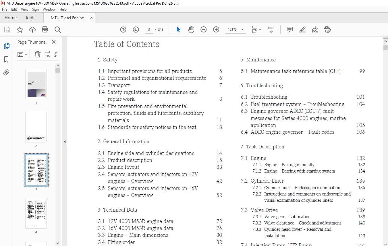

TABLE OF CONTENTS:
MTU Diesel Engine 12V 4000 M53R 16V 4000 M53R Operating Instructions Manual MS150036-02E PDF DOWNLOAD
Operating Instructions..................................................................................  1
	Table of Contents...................................................................................  3
	1 Safety............................................................................................  5
		1.1 Important provisions for all products.......................................................  5
		1.2 Personnel and organizational requirements...................................................  6
		1.3 Transport...................................................................................  7
		1.4 Safety regulations for maintenance and repair work..........................................  8
		1.5 Fire prevention and environmental protection, fluids and lubricants, auxiliary materials.... 11
		1.6 Standards for safety notices in the text.................................................... 13
	2 General Information............................................................................... 14
		2.1 Engine side and cylinder designations....................................................... 14
		2.2 Product description......................................................................... 15
		2.3 Engine layout............................................................................... 38
		2.4 Sensors, actuators and injectors on 12V engines – Overview.................................. 42
		2.5 Sensors, actuators and injectors on 16V engines – Overview.................................. 52
	3 Technical Data.................................................................................... 72
		3.1 12V 4000 M53R engine data................................................................... 72
		3.2 16V 4000 M53R engine data................................................................... 76
		3.3 Engine – Main dimensions.................................................................... 80
		3.4 Firing order................................................................................ 82
	4 Operation......................................................................................... 83
		4.1 Controls.................................................................................... 83
		4.2 Putting the engine into operation after extended out-of-service periods (>3 months)......... 84
		4.3 Putting the engine into operation after scheduled out-of-service-period..................... 85
		4.4 Starting the engine......................................................................... 86
		4.5 Operational checks.......................................................................... 87
		4.6 Tasks after extended out-of-service periods (>3 weeks)...................................... 88
		4.7 Checks prior to start-up.................................................................... 89
		4.8 Fuel treatment system – Putting into operation.............................................. 90
		4.9 Fuel treatment system – Switching on........................................................ 93
		4.10 Fuel treatment system – Shutdown........................................................... 94
		4.11 Stopping the engine........................................................................ 95
		4.12 Emergency engine stop...................................................................... 96
		4.13 After stopping the engine.................................................................. 97
		4.14 Plant – Cleaning........................................................................... 98
	5 Maintenance....................................................................................... 99
		5.1 Maintenance task reference table [QL1]...................................................... 99
	6 Troubleshooting...................................................................................101
		6.1 Troubleshooting.............................................................................101
		6.2 Fuel treatment system – Troubleshooting.....................................................104
		6.3 Engine governor ADEC (ECU 7) fault messages for Series 4000 engines, marine application.....105
		6.4 ADEC engine governor – Fault codes..........................................................106
	7 Task Description..................................................................................132
		7.1 Engine......................................................................................132
			7.1.1 Engine – Barring manually.............................................................132
			7.1.2 Engine – Barring with starting system.................................................134
		7.2 Cylinder Liner..............................................................................135
			7.2.1 Cylinder liner – Endoscopic examination...............................................135
			7.2.2 Instructions and comments on endoscopic and visual examination of cylinder liners.....137
		7.3 Valve Drive.................................................................................139
			7.3.1 Valve gear – Lubrication..............................................................139
			7.3.2 Valve clearance – Check and adjustment................................................140
			7.3.3 Cylinder head cover – Removal and installation........................................143
		7.4 Injection Pump / HP Pump....................................................................144
			7.4.1 HP pump – Filling with engine oil.....................................................144
			7.4.2 HP pump – Relief bore check...........................................................145
		7.5 Injection Valve / Injector..................................................................146
			7.5.1 Injector – Replacement................................................................146
			7.5.2 Injector – Removal and installation...................................................147
		7.6 Fuel Filter.................................................................................152
			7.6.1 Supplementary fuel filter – Overview..................................................152
			7.6.2 Additional fuel filter – Replacement..................................................153
			7.6.3 Fuel filter – Replacement.............................................................154
			7.6.4 Fuel prefilter – Differential pressure check and adjustment of gauge..................156
			7.6.5 Fuel prefilter – Draining.............................................................157
			7.6.6 Fuel prefilter – Flushing.............................................................159
			7.6.7 Fuel prefilter with water separator – Filter element replacement......................161
		7.7 Exhaust Turbocharger........................................................................163
			7.7.1 Compressor wheel – Cleaning...........................................................163
		7.8 Charge-Air Cooling..........................................................................171
			7.8.1 Charge-air cooler – Checking condensate drain for water discharge and obstruction.....171
		7.9 Air Filter..................................................................................172
			7.9.1 Air filter – Replacement..............................................................172
			7.9.2 Air filter – Removal and installation.................................................173
		7.10 Air Intake.................................................................................174
			7.10.1 Service indicator – Signal ring position check (optional)............................174
		7.11 Starting Equipment.........................................................................175
			7.11.1 Starter – Condition check............................................................175
		7.12 Lube Oil System, Lube Oil Circuit..........................................................176
			7.12.1 Engine oil – Level check.............................................................176
			7.12.2 Engine oil – Change..................................................................177
			7.12.3 Engine oil – Sample extraction and analysis..........................................179
		7.13 Oil Filtration / Cooling...................................................................181
			7.13.1 Checking oil indicator filter........................................................181
			7.13.2 Engine oil filter – Replacement......................................................183
			7.13.3 Centrifugal oil filter – Cleaning and filter sleeve replacement......................185
		7.14 Coolant Circuit, General, High-Temperature Circuit.........................................188
			7.14.1 Drain and vent points................................................................188
			7.14.2 Engine coolant level – Check.........................................................192
			7.14.3 Engine coolant – Change..............................................................193
			7.14.4 Engine coolant – Draining............................................................194
			7.14.5 Engine coolant – Filling.............................................................197
			7.14.6 HT coolant pump – Relief bore check..................................................199
			7.14.7 Engine coolant – Sample extraction and analysis......................................200
			7.14.8 Engine coolant filter – Replacement..................................................201
			7.14.9 Preheating unit......................................................................202
		7.15 Raw Water Pump with Connections............................................................205
			7.15.1 Raw water pump – Relief bore check...................................................205
		7.16 Battery-Charging Generator.................................................................206
			7.16.1 Battery-charging generator drive – Coupling condition check..........................206
		7.17 Engine Mounting / Support..................................................................207
			7.17.1 Engine mounting – Checking securing screws for firm seating..........................207
		7.18 Auxiliary PTO..............................................................................208
			7.18.1 Bilge pump – Relief bore check.......................................................208
		7.19 Fuel Supply System.........................................................................209
			7.19.1 Water drain valve – Check............................................................209
			7.19.2 Differential pressure gauge – Check..................................................210
			7.19.3 Water level probe (3-in-1 rod electrode) – Check.....................................211
			7.19.4 Pump capacity – Check................................................................212
			7.19.5 Coalescer filter element – Replacement...............................................213
		7.20 Wiring (General) for Engine/Gearbox/Unit...................................................215
			7.20.1 Engine wiring harness ‒ Overview.....................................................215
			7.20.2 Engine wiring – Check................................................................224
		7.21 Accessories for (Electronic) Engine Governor / Control System..............................225
			7.21.1 Limit switch for start interlock ‒ Check.............................................225
			7.21.2 Engine Control Unit ECU 7 – Checking plug connections................................226
			7.21.3 Engine monitoring unit EMU – Plug connection check...................................227
			7.21.4 Interface module EIM plug connections – Check........................................228
			7.21.5 Engine Control Unit ECU 7 – Removal and installation.................................229
			7.21.6 EMU 7 – Removal and installation.....................................................230
			7.21.7 Engine Interface Module EIM – Removal and installation...............................231
			7.21.8 Diagnostic features of EIM...........................................................232
			7.21.9 CDC parameters – Reset...............................................................235
	8 Appendix A........................................................................................236
		8.1 Abbreviations...............................................................................236
		8.2 MTU contact persons/service partners........................................................238
	9 Appendix B........................................................................................239
		9.1 Special Tools...............................................................................239
		9.2 Index.......................................................................................246
VIDEO PRVIEW:
DESCRIPTION:
MTU Diesel Engine 12V 4000 M53R 16V 4000 M53R Operating Instructions Manual MS150036-02E PDF DOWNLOAD
1 Safety
1.1 Important provisions for all products
Nameplate
- The product is identified by nameplate, model designation, or serial number and must match with the information on the title page of this manual.
- Nameplate, model designation, or serial number can be found on the product.
General information
- This product may pose a risk of injury or damage in the following cases:
- Incorrect use
- Operation, maintenance, and repair by unqualified personnel
- Modifications or conversions
- Noncompliance with the safety instructions and warning notices
Correct use
- The product is intended exclusively for the application specified in the contract or defined at the time of delivery.
- This means that the equipment must be operated:
- Within the permissible operating parameters in accordance with the (→ Technical data)
- With fluids and lubricants approved by the manufacturer in accordance with the (→ Fluids and Lubricants Specifications of the manufacturer)
- With spare parts approved by the manufacturer in accordance with the (→ Spare Parts Catalog/MTU contact/Service partner)
- In the original as-delivered configuration or in a configuration approved by the manufacturer in writing (including engine control/parameters)
- In compliance with all safety regulations and in adherence with all warning notices in this manual
- In accordance with the maintenance requirements over the entire service life of the product (→ Maintenance Schedule)
- In compliance with the maintenance and repair instructions contained in this manual, in particular with regard to the specified tightening torques
- With the exclusive use of technical personnel trained in commissioning, operation, maintenance, and repair
- By contracting only workshops authorized by the manufacturer to carry out repair and overhaul
- Any other use is considered improper use and increases the risk of personnel injury or material damage in product operation. The manufacturer will accept no liability for such damage.
Modifications or conversions
- Unauthorized modifications to the product compromise safety.
- The manufacturer will accept no liability or warranty claims for any damage caused by unauthorized modifications or conversions.
Spare parts
- Only genuine spare parts must be used to replace components or assemblies.
- The manufacturer will accept no liability or warranty claims for any damage caused by the use of other.
PLEASE NOTE:
- This is the same manual used by the dealers to diagnose and troubleshoot your vehicle
- You will be directed to the download page as soon as the purchase is completed. The whole payment and downloading process will take anywhere between 2-5 minutes
- Need any other service / repair / parts manual, please feel free to contact [email protected] . We still have 50,000 manuals unlisted
S.S


