

Massey Ferguson MF6400 Series Tractor Workshop Manual
FILE DETAILS:
Massey Ferguson MF6400 Series Tractor Workshop Manual
Language: English
Size: 241 MB
Pages: 4029
Format: PDF
Downloadable: YES
DESCRIPTION:
Massey Ferguson MF6400 Series Tractor Workshop Manual
General:
The purpose of this manual is to assist Dealers and Agents in the efficient installation, servicing and repair of Massey Ferguson equipment. If the procedures are carried out as detailed and specialised tools are used where appropriate, the operations should be completed within the times stated in the repair time schedule.
Repairs and parts replacement:
When parts have to be replaced, it is essential that only genuine Massey Ferguson parts are used. The following points are of particular importance when carrying out repairs and fitting replacement parts and accessories. Tractor safety may be compromised if non-genuine parts are fitted. Legislation in certain countries prohibits the fitting of parts that do not comply with the tractor manufacturer’s specifications.
- Torque wrench setting figures given in the workshop manual must be strictly adhered to. Locking devices must be fitted where specified. If the efficiency of a locking device is impaired during disassembly, it must be replaced.
- The tractor warranty may be invalidated if non-genuine Massey Ferguson parts are fitted. All Massey Ferguson parts are guaranteed by the manufacturer. Massey Ferguson Dealers and Agents are required to supply genuine parts only.
TABLE OF CONTENTS:
Massey Ferguson MF6400 Series Tractor Workshop Manual
Chapter 1 Intro Specifications.pdf............................................................................................   1
	01 - Introduction - Specifications........................................................................................   2
		1A10 - Using the manual...............................................................................................   4
			A . General.......................................................................................................   6
			B . Structure of the manual.......................................................................................   6
			C . Service tools.................................................................................................   6
			D . Repairs and replacements......................................................................................   6
		1B10 - SPECIFICATIONS - General specifications........................................................................   8
			A . Model 6445....................................................................................................  10
			B . Model 6455....................................................................................................  13
			C . Model 6460....................................................................................................  16
			D . Model 6465....................................................................................................  19
			E . Model 6470....................................................................................................  22
			F . Model 6475....................................................................................................  25
			G . Model 6480....................................................................................................  28
			H . Model 6485....................................................................................................  31
			I . Model 6490....................................................................................................  33
			J . Model 6495....................................................................................................  35
			K . Model 6497....................................................................................................  37
			L . Model 6499....................................................................................................  39
		1B11 - SPECIFICATIONS - Ground speeds.................................................................................  42
			A . 6445..........................................................................................................  44
			B . 6455..........................................................................................................  45
			C . 6460, 6465, 6470..............................................................................................  46
			D . 6475, 6480....................................................................................................  47
			E . 6485..........................................................................................................  48
			F . 6490..........................................................................................................  49
			G . 6490, 6495, 6497..............................................................................................  50
			H . 6497, 6499....................................................................................................  51
		1B12 - SPECIFICATIONS - Dimensions....................................................................................  52
			A . Adjusting track width.........................................................................................  54
			B . Attachment points and dimensions..............................................................................  56
		1B13 - SPECIFICATIONS - Capacities....................................................................................  62
			A . Capacities....................................................................................................  64
		1C10 - Miscellaneous..................................................................................................  66
			A . Conversion tables.............................................................................................  68
			B . Retaining compounds and sealing products......................................................................  69
			C . Tightening torques............................................................................................  70
Chapter 2 Splitting The Tractor.pdf...........................................................................................  74
	02 - Splitting the tractor................................................................................................  74
		02A01 - Splitting - Front frame / Perkins engine......................................................................  76
			A . General.......................................................................................................  77
			B . Disassembling and reassembling (Perkins 6-cylinder engine)....................................................  77
			C . Disassembling and reassembling (Perkins 4-cylinder engine)....................................................  84
			D . Shimming the front frame (Perkins 4-cylinder EEM engine)......................................................  91
		02A02 - Splitting - Front frame / Sisu engine.........................................................................  94
			A . General.......................................................................................................  95
			B . Disassembling.................................................................................................  95
			C . Reassembling.................................................................................................. 100
		2A30 - Splitting the front frame/Sisu engine - MF 6497-6499........................................................... 102
			A . General....................................................................................................... 104
			B . Disassembly................................................................................................... 105
			C . Reassembly.................................................................................................... 111
		02B01 - Splitting - Perkins Engine / GBA20 Gearbox.................................................................... 114
			A . General....................................................................................................... 116
			B . Disassembling and reassembling (Perkins 6-cylinder engine).................................................... 117
			C . Disassembling and reassembling (Perkins 4-cylinder engine).................................................... 125
		2B11 - Perkins/GTA2520 engine separation.............................................................................. 134
			A . General....................................................................................................... 136
			B . Disassembling and reassembling (six-cylinder Perkins engine).................................................. 137
			C . Disassembling and reassembling (four-cylinder Perkins engine)................................................. 146
		02B02 - Splitting - Sisu Engine / GBA10 Gearbox....................................................................... 156
			A . General....................................................................................................... 157
			B . Disassembly................................................................................................... 158
			C . Reassembly.................................................................................................... 163
		2B21 - Splitting the Sisu engine/GTA1030.............................................................................. 166
			A . General....................................................................................................... 168
			B . Disassembly................................................................................................... 169
			C . Reassembly.................................................................................................... 175
		02C01 - Splitting - GBA20 gearbox / Centre housing.................................................................... 178
			A . General....................................................................................................... 179
			B . Disassembling and reassembling with the cab fixed to the centre housing....................................... 180
			C . Disassembling and reassembling with the cab fixed to the gearbox.............................................. 187
		02C02 - Splitting - GBA10 gearbox / Centre housing.................................................................... 194
			A . General....................................................................................................... 195
			B . Disassembling and reassembling with the cab fixed to the centre housing....................................... 196
			C . Disassembling and reassembling with the cab fixed to the gearbox.............................................. 203
		2C30 - GBA25/GPA20 separation......................................................................................... 210
			A . General....................................................................................................... 212
			B . Disassembly and reassembly with the cab fixed to the centre housing........................................... 213
			C . Disassembling and reassembling with the cab fixed to the gearbox.............................................. 220
		2C40 - GBA10/GPA30 separation......................................................................................... 228
			A . General....................................................................................................... 230
			B . Disassembly and reassembly with the cab fixed to the rear axle................................................ 231
			C . Disassembly and reassembly with the cab fixed to the gearbox.................................................. 240
		2D10 - Intermediate housing/centre housing separation - GPA30......................................................... 248
			A . General....................................................................................................... 250
			B . Preliminary operations........................................................................................ 250
			C . Disassembly................................................................................................... 251
			D . Reassembly.................................................................................................... 253
			E . Final operation............................................................................................... 253
		02D01 - Splitting - PTO housing / Centre housing...................................................................... 254
			A . General....................................................................................................... 255
			B . Preliminary operations........................................................................................ 255
			C . Disassembling................................................................................................. 257
			D . Reassembling.................................................................................................. 257
			E . Final operations.............................................................................................. 259
		2E20 - Centre housing/PTO housing separation - GPA30.................................................................. 260
			A . General....................................................................................................... 262
			B . Preliminary operations........................................................................................ 262
			C . Disassembly................................................................................................... 263
			D . Reassembly.................................................................................................... 265
			E . Final operations.............................................................................................. 267
		2F10 - Reinforcements - GTA1040....................................................................................... 268
			A . General....................................................................................................... 270
			B . Installation of reinforcements on the GBA10 gearbox........................................................... 271
		2F11 - Reinforcements - GTA1030....................................................................................... 274
			A . General....................................................................................................... 276
			B . Installation of reinforcements on the Sisu engine............................................................. 277
			C . Installation of reinforcements on the GBA10 gearbox........................................................... 277
Chapter 3 Engine.pdf.......................................................................................................... 280
	03 - Engine............................................................................................................... 280
		3A10 - PERKINS ENGINE - General....................................................................................... 282
			A . Introduction.................................................................................................. 284
			B . Specifications and standards concerning fuel, oil and coolant................................................. 284
			C . Main characteristics.......................................................................................... 285
		03C02 - Perkins EEM - Disassembling and reassembling.................................................................. 292
			A . Replacing the electronic control module (ECM)................................................................. 294
			B . Disassembling the fuel injection pump......................................................................... 295
			C . Reassembling the fuel injection pump.......................................................................... 297
			D . 1st piston timing 4 beyond TDC............................................................................... 299
			E . Service tools................................................................................................. 300
		03D01 - Spacer - Perkins Engine....................................................................................... 302
			A . General....................................................................................................... 303
			B . Replacing the lip seal........................................................................................ 303
			C . Removing and refitting the spacer (6- and 4-cylinder engines)................................................. 304
			D . Service tool.................................................................................................. 308
		3B10 - SISU ENGINE - General.......................................................................................... 310
			A . Introduction.................................................................................................. 312
			B . Specifications and standards concerning fuel, oil and coolant................................................. 312
			C . Main characteristics.......................................................................................... 313
		03C01 - EEM2 SisuDiesel - Disassembling and reassembling.............................................................. 318
			A . Replacing the electronic control unit (ECU)................................................................... 320
			B . Disassembling the fuel injection pump......................................................................... 321
			C . Reassembling the fuel injection pump.......................................................................... 322
			D . Service tool.................................................................................................. 323
		3B12 - SISU ENGINE - Spacer........................................................................................... 324
			A . General....................................................................................................... 326
			B . Removing - refitting the cover and replacing the lip seal..................................................... 327
			C . Removing - refitting the spacer............................................................................... 330
			D . Service tool.................................................................................................. 335
		3B13 - SISU ENGINE - Engine/GTA1030 transmission link................................................................. 336
			A . General....................................................................................................... 338
			B . Removing - refitting the vibration damper..................................................................... 341
			C . Removing - refitting the engine flywheel...................................................................... 342
			D . Replacing the sealed bearing.................................................................................. 344
			E . Replacing the starter ring gear............................................................................... 345
			F . Service tool.................................................................................................. 346
Chapter 5 Gearbox.pdf......................................................................................................... 348
	05 - Gearbox.............................................................................................................. 348
		05A01 - General - GBA20 operation..................................................................................... 350
			A . General....................................................................................................... 354
			B . Construction and description.................................................................................. 355
			C . Operation..................................................................................................... 356
			D . Specifications for transmission with power shuttle, Dynashift and input gear train............................ 359
		05B01 - GBA20 input unit.............................................................................................. 362
			A . General....................................................................................................... 363
			B . Preliminary operations........................................................................................ 364
			C . Removal....................................................................................................... 365
			D . Refitting..................................................................................................... 366
			E . Adjusting the progressivity sensor............................................................................ 367
			F . Final operations.............................................................................................. 368
			G . Service tools................................................................................................. 368
		05C01 - GBA20 Power shuttle........................................................................................... 370
			A . General....................................................................................................... 372
			A . Removing and refitting the forward clutch..................................................................... 380
			B . Disassembling and reassembling the forward clutch............................................................. 381
			C . Shimming the forward clutch................................................................................... 383
			D . Disassembling and reassembling the reverse clutch............................................................. 384
			E . Disassembling and reassembling the drive pinion - Shimming the shaft.......................................... 388
			F . Service tools................................................................................................. 390
		05E01 - GBA20 Dynashift............................................................................................... 392
			A . General....................................................................................................... 393
			B . Operating principle........................................................................................... 393
			C . Preliminary operations........................................................................................ 400
			D . Removing and disassembling the cover, housing, forward clutch and brake....................................... 400
			E . Removing and splitting the planet carrier assembly............................................................ 402
			F . Disassembling the reverse clutch and brake.................................................................... 403
			G . Assembling the planet carriers................................................................................ 403
			H . Reassembling the reverse clutch and the brake................................................................. 404
			I . Refitting the cover, forward clutch, brake and housing........................................................ 405
			J . Shimming the planet carriers.................................................................................. 406
			K . Assembling and fitting the input unit......................................................................... 407
			L . Service tools................................................................................................. 408
		05G01 - GBA20 Selector rails.......................................................................................... 410
			A . General....................................................................................................... 411
			B . Servicing guide............................................................................................... 414
			C . Creeper fork.................................................................................................. 415
			D . Hare and Tortoise fork - Mechanical lock assembly - 1st /2nd - 3rd / 4th forks - Selector rail................ 419
			E . Service tools................................................................................................. 426
		05H01 - GBA20 Output shaft............................................................................................ 428
			A . General....................................................................................................... 429
			B . Preliminary operations........................................................................................ 432
			C . Removing and refitting the selector rail and the forks........................................................ 432
			D . Removing, refitting and shimming the shaft.................................................................... 433
			E . Final operations.............................................................................................. 437
		05I01 - GBA20 Mainshaft............................................................................................... 438
			A . General....................................................................................................... 439
			B . Preliminary operations........................................................................................ 442
			C . Disassembling and reassembling the shaft...................................................................... 442
			D . Final operations.............................................................................................. 444
			E . Service tools................................................................................................. 445
		05J01 - GBA20 Layshaft................................................................................................ 446
			A . General....................................................................................................... 447
			B . Final operations.............................................................................................. 449
			C . Removing and refitting the shaft and pinion assembly.......................................................... 449
			D . Removing and refitting pinions................................................................................ 450
			E . Replacing the taper roller bearings and the shaft (54)........................................................ 451
			F . Shimming the pinions.......................................................................................... 451
			G . Shimming the shaft............................................................................................ 452
			H . Final operations.............................................................................................. 453
			I . Service tool.................................................................................................. 453
		5A20 - GBA20 - Super Creeper unit..................................................................................... 454
			A . General....................................................................................................... 456
			B . Kinematics and operation...................................................................................... 461
			C . Removing-refitting and disassembling-reassembling the epicyclic gear trains................................... 465
			D . Disassembling-reassembling the planet carriers................................................................ 467
			E . Adjusting the control......................................................................................... 471
		5B10 - GBA10 - General - Operation.................................................................................... 472
			A . General....................................................................................................... 474
			B . Operation..................................................................................................... 478
			C . Specifications................................................................................................ 479
			D . Tightening torques and sealing products....................................................................... 481
		5B11 - GBA10 - Input unit............................................................................................. 484
			A . General....................................................................................................... 486
			B . Preliminary operations........................................................................................ 487
			C . Removal....................................................................................................... 489
			D . Refitting..................................................................................................... 491
			E . Adjusting of the progressivity sensor......................................................................... 492
			F . Final operations.............................................................................................. 492
			G . Service tools................................................................................................. 493
		5B12 - GBA10 - PowerShuttle........................................................................................... 494
			A . General....................................................................................................... 496
			B . Removing - refitting the forward clutch....................................................................... 508
			C . Disassembling - reassembling the forward clutch............................................................... 509
			D . Shimming the forward clutch................................................................................... 514
			E . Disassembling - reassembling the reverse clutch............................................................... 515
			F . Disassembling - reassembling the driving pinion - Shimming the shaft.......................................... 519
			G . Service tools................................................................................................. 522
		5B13 - GBA10 - Dynashift.............................................................................................. 524
			A . General....................................................................................................... 526
			B . Operating principle........................................................................................... 526
			C . Preliminary operations........................................................................................ 536
			D . Removing and disassembling the cover, housing, front clutch and brake......................................... 537
			E . Removing and splitting the planet carrier unit................................................................ 539
			F . Disassembling the rear clutch and brake....................................................................... 539
			G . Assembling the planet carriers................................................................................ 539
			H . Reassembling the rear clutch and the brake.................................................................... 541
			I . Refitting the cover, front clutch, brake and housing.......................................................... 542
			J . Shimming the planet carriers.................................................................................. 545
			K . Assembling the input unit..................................................................................... 547
			L . Final operations.............................................................................................. 547
			M . Service tools................................................................................................. 548
		5B14 - GBA10 - Selector cover......................................................................................... 550
			A . General....................................................................................................... 552
			B . Identification and functions of components.................................................................... 560
			C . Removing - refitting the cover................................................................................ 563
			D . Replacing Hare / Tortoise piston seals........................................................................ 565
			E . Disassembling - reassembling the selector mechanism........................................................... 565
			F . Adjusting the Hare / Tortoise range........................................................................... 567
			G . Fitting and adjusting the gear cables......................................................................... 568
			H . Service tool.................................................................................................. 571
		5B15 - GBA10 - Selector rails......................................................................................... 572
			A . General....................................................................................................... 574
			B . Servicing guide............................................................................................... 579
		5B16 - GBA10 - Output shaft........................................................................................... 582
			A . General....................................................................................................... 584
			B . Preliminary operations........................................................................................ 589
			C . Removing - refitting the selector rails and forks............................................................. 589
			D . Removing - refitting and shimming the shaft................................................................... 589
			E . Final operations.............................................................................................. 593
		5B17 - GBA10 - Mainshaft.............................................................................................. 594
			A . General....................................................................................................... 596
			B . Preliminary operations........................................................................................ 601
			C . Disassembling - reassembling the shaft........................................................................ 601
			D . Final operations.............................................................................................. 603
			E . Shimming the shaft............................................................................................ 604
			F . Service tools................................................................................................. 605
		5B18 - GBA20 - Layshaft............................................................................................... 606
			A . General....................................................................................................... 608
			B . Preliminary operations........................................................................................ 613
			C . Removing and disassembling the layshaft....................................................................... 614
			D . Reassembling and refitting the layshaft....................................................................... 615
			E . Final operations.............................................................................................. 616
			F . Shimming the pinions.......................................................................................... 617
			G . Shimming the bearings......................................................................................... 618
			H . Service tools................................................................................................. 620
		5B19 - GBA10 - Creeper unit........................................................................................... 622
			A . General....................................................................................................... 624
			B . Operation..................................................................................................... 625
			C . Removing - refitting the unit................................................................................. 634
			D . Disassembling - reassembling and adjusting the selector mechanism (GPA40)..................................... 635
			E . Disassembling - reassembling and adjusting the selector mechanism (GPA30)..................................... 639
			F . Disassembling - reassembling the epicyclical gear reducer unit................................................ 643
			G . Adjusting the control......................................................................................... 644
		5C10 - GBA25 - General - Operation.................................................................................... 646
			A . General....................................................................................................... 648
			B . Construction and description.................................................................................. 656
			C . Kinematics of the GBA25 gearbox............................................................................... 659
			D . Synchronisers................................................................................................. 662
			E . Main unit robotic control..................................................................................... 666
			F . GBA25 - disassembly steps..................................................................................... 667
			G . GBA25 transmission spécifications............................................................................. 673
		5C11 - GBA25 - PowerShuttle........................................................................................... 678
			A . General....................................................................................................... 680
			B . Preliminary operations........................................................................................ 686
			C . Removing and refitting the PowerShuttle....................................................................... 687
			D . Removing and refitting the PowerShuttle....................................................................... 691
			E . Final operations.............................................................................................. 695
			F . Service tools................................................................................................. 696
		5C12 - GBA25 - Powershift module...................................................................................... 698
			A . General....................................................................................................... 700
			B . Operating principle........................................................................................... 700
			C . Kinematics.................................................................................................... 706
			D . Preliminary operations........................................................................................ 714
			E . Removing and refitting the Powershift module.................................................................. 715
			F . Disassembling and reassembling the Dynashift module........................................................... 718
			G . Disassembling and reassembling the speed multiplier module.................................................... 726
			H . Disassembling and reassembling the planet gears............................................................... 729
			I . Final operations.............................................................................................. 730
			J . Service tools................................................................................................. 731
		5C13 - GBA25 - Robotic mechanical gearbox............................................................................. 732
			A . General....................................................................................................... 734
			B . Operating principle........................................................................................... 734
			C . Description and kinematics of ratios.......................................................................... 742
			D . Preliminary operations........................................................................................ 744
			E . Removing and refitting the primary and secondary shafts....................................................... 745
			F . Disassembling and reassembling the primary and secondary shafts............................................... 751
			G . Shimming the primary and secondary shafts in the housing...................................................... 757
			H . Adjusting the selector rails and forks........................................................................ 759
			I . Adjusting the safety finger................................................................................... 764
			J . Assembling the intermediate speed sensor...................................................................... 765
			K . Final operations.............................................................................................. 765
			L . Service tools................................................................................................. 766
		5C14 - GBA25 - Creeper unit........................................................................................... 768
			A . General....................................................................................................... 770
			B . Operation..................................................................................................... 770
			C . Removing the creeper unit and the ring gear................................................................... 774
			D . Removing the planet carrier................................................................................... 774
			E . Reassembling the planet carrier, refitting the ring gear and the unit......................................... 774
			F . Final operations.............................................................................................. 775
			G . Adjusting the control......................................................................................... 776
		5C15 - GBA25 - Super Creeper unit..................................................................................... 778
			A . General....................................................................................................... 780
			B . Kinematics and operation...................................................................................... 785
			C . Removing-refitting and disassembling-reassembling the epicyclic gear trains................................... 789
			D . Disassembling-reassembling the planet carriers................................................................ 791
			E . Final steps................................................................................................... 795
			F . Adjusting the control......................................................................................... 795
		5D10 - GBA15 - General - Operation.................................................................................... 796
			A . General....................................................................................................... 798
			B . Powershift module and PowerShuttle............................................................................ 812
			C . Main gearbox.................................................................................................. 815
			D . Synchronisers................................................................................................. 817
			E . GBA15 gearbox dismantling steps............................................................................... 820
			F . Transmission specifications................................................................................... 825
Chapter 06 Rear Axle.pdf...................................................................................................... 830
	06 - Rear axle............................................................................................................ 830
		06A01 - General - GPA20 operation..................................................................................... 832
			A . General....................................................................................................... 833
			B . Centre housing assembly....................................................................................... 833
		06B01 - GPA 20 Normal Duty trumpet housings........................................................................... 836
			A . General....................................................................................................... 837
			B . Trumpet assembly.............................................................................................. 840
			C . Planet carrier................................................................................................ 842
			D . Bearings and seals............................................................................................ 843
			E . Preloading the axle shaft bearings............................................................................ 844
			F . Replacing a wheel stud........................................................................................ 845
		06C01 - GPA20 brake pistons........................................................................................... 846
			A . General....................................................................................................... 847
			B . Disassembly................................................................................................... 848
			C . Reassembly.................................................................................................... 849
		06E01 - GPA20 handbrake unit and control.............................................................................. 852
			A . General....................................................................................................... 853
			B . Operation..................................................................................................... 853
			C . Disassembly................................................................................................... 856
			D . Reassembly.................................................................................................... 858
			E . Assembling and adjusting the control.......................................................................... 862
		06F01 - GPA20 differential............................................................................................ 864
			A . General....................................................................................................... 865
			B . Removing the left-hand flange and differential lock assembly.................................................. 868
			C . Disassembling and reassembling the differential lock assembly................................................. 869
			D . Refitting the left-hand flange and the differential lock assembly............................................. 870
			E . Removing the differential assembly............................................................................ 872
			F . Disassembling the differential assembly and the ring gear..................................................... 873
			G . Removing and disassembling the drive pinion................................................................... 874
			H . Reassembling the ring gear and differential assembly.......................................................... 875
			I . Adjusting the bevel gear distance, refitting and shimming the drive pinion.................................... 876
			J . Refitting and shimming of the differential assembly........................................................... 880
			K . Adjusting and checking the backlash........................................................................... 884
			L . Service tool.................................................................................................. 886
		06G01 - GPA20 Hitch / Linkage......................................................................................... 888
			A . General....................................................................................................... 889
			B . Removing the cover............................................................................................ 892
			C . Disassembling the cover....................................................................................... 893
			D . Reassembling the cover........................................................................................ 894
			E . Refitting the cover........................................................................................... 896
			F . Rear hitch.................................................................................................... 898
			G . Description of the hitch...................................................................................... 898
			H . Disassembling and reassembling a lift ram..................................................................... 901
		06H01 - GPA20 Auto-hitch.............................................................................................. 902
			A . General....................................................................................................... 903
			B . Presentation of brackets and Dromone auto-hitch (Fig. 1)...................................................... 903
			C . Adjusting auto-hitch tie-rods and the control................................................................. 906
			D . Operating principle of the Dromone retractable hook........................................................... 908
		06I01 - GPA20 rear wheels / hubs...................................................................................... 910
			A . General....................................................................................................... 911
			B . Description of assembly with flanged axle shaft and tightening torque for nuts................................ 911
			C . Changing wheel track.......................................................................................... 912
			D . Replacing a wheel stud........................................................................................ 912
		6B10 - GPA40 - General - Operation.................................................................................... 914
			A . General....................................................................................................... 916
			B . Layout of main components..................................................................................... 917
			C . Specifications of the 40 kph GPA40 rear axle.................................................................. 929
			D . Specifications of the 50 kph GPA40 rear axle.................................................................. 939
		06B02 - GPA40 Normal Duty Trumpet housings............................................................................ 946
			A . General....................................................................................................... 948
			B . Removing and refitting the trumpet assembly................................................................... 952
			C . Disassembling and reassembling the planet carrier............................................................. 954
			D . Replacing bearings and seals.................................................................................. 956
			E . Shimming the axle shaft bearings.............................................................................. 958
			F . Replacing a wheel stud on the flange shaft.................................................................... 959
		06B03 - GPA40 Heavy Duty Trumpet housings............................................................................. 960
			A . General....................................................................................................... 961
			B . Removing and refitting the trumpet assembly................................................................... 964
			C . Removing and refitting the brake plate and ring gear assembly................................................. 966
			D . Removing and disassembling the planet carrier................................................................. 967
			E . Reassembling and refitting the planet carrier................................................................. 968
			F . Replacing the axle shaft bearings............................................................................. 969
			G . Shimming the axle shaft bearings.............................................................................. 971
			H . Replacing a wheel stud on the axle flange..................................................................... 972
		06B04 - GPA40 Sealed Heavy Duty Trumpet housings...................................................................... 974
			A . General....................................................................................................... 975
			B . Removing and refitting the trumpet assembly................................................................... 978
			C . Removing and refitting the compartment and ring gear assembly................................................. 980
			D . Replacing compartment seals................................................................................... 981
			E . Removing and disassembling the planet carrier................................................................. 982
			F . Reassembling and refitting the planet carrier................................................................. 982
			G . Replacing the axle shaft bearings............................................................................. 983
			H . Shimming the axle shaft bearings.............................................................................. 985
			I . Service tools................................................................................................. 987
		06C02 - GPA40 brake pistons........................................................................................... 988
			A . General....................................................................................................... 989
			B . Preliminary operations........................................................................................ 994
			C . Removing a piston............................................................................................. 994
			D . Refitting a piston............................................................................................ 995
			E . Final operations.............................................................................................. 997
			F . Service tool.................................................................................................. 997
		06D01 - GPA40 Drive pinion............................................................................................ 998
			A . General....................................................................................................... 999
			B . Removing, refitting and disassembling - reassembling the drive pinion and unit assembly.......................1003
			C . Shimming the drive pinion and adjusting its position..........................................................1008
			D . Service tools.................................................................................................1013
		06E02 - GPA40 handbrake unit and control..............................................................................1014
			A . General.......................................................................................................1015
			B . Disassembling, reassembling and refitting the handbrake unit and control......................................1018
			C . Layout of components..........................................................................................1020
			D . Adjusting the handbrake.......................................................................................1024
			E . Removing and refitting the lever..............................................................................1026
		06F02 - GPA40 - 5" differential unit and hydromechanical lock.........................................................1028
			A . General.......................................................................................................1029
			B . Removing and refitting the left- hand differential unit support, reassembling the lock assembly...............1032
			C . Removing and refitting the right- hand differential support...................................................1036
			D . Removing and refitting the differential unit..................................................................1038
			E . Removing and refitting the pinion gears and sun gears and disassembling and reassembling the ring gear........1040
			F . Adjusting and checking the backlash...........................................................................1042
			G . Shimming the differential unit................................................................................1043
			H . Service tools.................................................................................................1048
		06F03 - GPA40 - 5" differential unit and multidisc lock...............................................................1050
			A . General.......................................................................................................1052
			B . Removing and refitting the left- hand differential support and seal rings.....................................1056
			C . Removing and refitting the right- hand differential support...................................................1061
			D . Removing and refitting the differential unit..................................................................1064
			E . Removing and refitting the multidisc differential lock........................................................1066
			F . Removing and refitting pinion gears and sun gears - Disassembling and reassembling the ring gear..............1068
			G . Adjusting and checking the backlash...........................................................................1070
			H . Shimming the differential unit................................................................................1072
			I . Service tools.................................................................................................1075
		06F04 - GPA40 - 7" differential unit and multidisc lock...............................................................1076
			A . General.......................................................................................................1078
			B . Removing and refitting the left- hand differential support and seal rings.....................................1082
			C . Removing and refitting the right- hand differential support...................................................1086
			D . Removing and refitting the differential unit..................................................................1089
			E . Removing and refitting the multidisc differential lock........................................................1091
			F . Removing and refitting pinion gears and sun gears - Disassembling and reassembling the ring gear..............1093
			G . Adjusting and checking the backlash...........................................................................1096
			H . Shimming the differential unit................................................................................1098
			I . Service tools.................................................................................................1101
		06G02 - GPA40 hitch and linkage mechanisms............................................................................1102
			A . General.......................................................................................................1103
			B . Attaching cylinders...........................................................................................1110
			C . Preliminary operations........................................................................................1112
			D . Removing and refitting the bearings and single-piece lift arms................................................1113
			E . Disassembling and reassembling bearings.......................................................................1115
			F . Removing and refitting the main beam..........................................................................1115
			G . Final operations..............................................................................................1116
			H . Description, disassembling and reassembling the rear hitch mechanism and a ram................................1117
			I . Fitting the sensor............................................................................................1120
		06H02 - GPA40 Auto-hitch control......................................................................................1122
			A . General.......................................................................................................1123
			B . Adjusting tie-rods and control................................................................................1123
			C . Operating principle of the Dromone retractable hook...........................................................1125
		06I02 - Rear wheels / GPA40 Hubs......................................................................................1128
			A . General.......................................................................................................1129
			B . Description of the main assemblies and torque values..........................................................1130
			C . Changing wheel track..........................................................................................1135
			D . Replacing a wheel stud........................................................................................1136
		6C10 - GPA30 - General - Operation....................................................................................1138
			A . General.......................................................................................................1140
			B . Layout of main components.....................................................................................1141
			C . GPA30 rear axle specifications................................................................................1143
		6C11 - GPA30 - Heavy Duty Sealed trumpet housings.....................................................................1148
			A . General.......................................................................................................1150
			B . Removing - refitting the trumpet assembly.....................................................................1156
			C . Removing - refitting the sealed compartment and ring gear assembly............................................1157
			D . Replacing sealed compartment seals............................................................................1159
			E . Removing and disassembling the planet carrier.................................................................1160
			F . Reassembling and refitting the planet carrier.................................................................1161
			G . Replacing axle shaft bearings and seals.......................................................................1161
			H . Shimming the axle shaft bearings..............................................................................1163
			I . Service tools.................................................................................................1165
		6C12 - GPA30 - Trumpets housings with composite drive unit............................................................1166
			A . General.......................................................................................................1168
			B . Epicyclic gear train kinematics...............................................................................1173
			C . Removing - refitting the trumpet assembly.....................................................................1174
			D . Removing - refitting the spacer and ring gear assembly........................................................1178
			E . Replacing the spacer seals....................................................................................1180
			F . Replacing the cassette seal...................................................................................1181
			G . Removing and disassembling the planet carrier.................................................................1182
			H . Reassembling and refitting the planet carrier.................................................................1184
			I . Shimming the planet gears.....................................................................................1186
			J . Replacing axle shaft bearings and seals.......................................................................1187
			K . Shimming the axle shaft bearings..............................................................................1188
			L . Service tools.................................................................................................1190
		6C13 - GPA30 - Brake pistons..........................................................................................1192
			A . General.......................................................................................................1194
			B . Preliminary operations........................................................................................1199
			C . Removing a piston.............................................................................................1199
			D . Preparing and refitting a piston..............................................................................1201
			E . Final operations..............................................................................................1204
			F . Service tool..................................................................................................1204
		6C14 - GPA30 - Drive pinion...........................................................................................1206
			A . General.......................................................................................................1208
			B . Removing - refitting and disassembling - reassembling the unit/drive pinion...................................1212
			C . Adjusting drive pinion position and bearing shimming..........................................................1218
			D . Service tools.................................................................................................1223
		6C15 - GPA30 - Handbrake unit and control.............................................................................1224
			A . General.......................................................................................................1226
			B . Disassembling - reassembling the handbrake unit...............................................................1232
			C . Removing/disassembling and reassembling/refitting the handbrake linkage.......................................1235
			D . Adjusting the control.........................................................................................1237
			E . Removing - refitting the lever and replacing the cable........................................................1239
		6C16 - GPA30 - 7" differential unit and multidisc lock................................................................1242
			A . General.......................................................................................................1244
			B . Removing - refitting the left-hand differential support and seal rings........................................1249
			C . Removing - refitting the right-hand differential support......................................................1254
			D . Removing - refitting the differential unit....................................................................1257
			E . Removing - refitting the multidisc differential lock..........................................................1259
			F . Removing - refitting planet gears and sun gears...............................................................1261
			G . Removing - refitting the ring gear............................................................................1263
			H . Adjusting and checking the backlash...........................................................................1264
			I . Shimming the differential unit assembly.......................................................................1266
			J . Service tools.................................................................................................1269
		6C17 - GPA30 - Hitch and linkage mechanisms...........................................................................1270
			A . General.......................................................................................................1272
			B . Attaching a ram...............................................................................................1277
			C . Preliminary operations........................................................................................1279
			D . Removing - refitting the lift arm/shaft and supports/bearings assembly........................................1280
			E . Removing - refitting the lift supports/bearings...............................................................1286
			F . Final operations..............................................................................................1287
			G . Description, disassembling - reassembling the rear hitch mechanism and a lift ram.............................1288
			H . Service tools.................................................................................................1293
		6C18 - GPA30 - Auto-hitch.............................................................................................1294
			A . General.......................................................................................................1296
			B . Operating principle of the Dromone auto-hitch.................................................................1296
			C . Adjusting tie-rods and control................................................................................1299
			D . Tightening torques............................................................................................1302
		6C19 - GPA30 - Rear wheels/Hubs.......................................................................................1304
			A . General.......................................................................................................1306
			B . Description of the main assembly fits and torque values.......................................................1309
			C . Rear wheel track adjustment...................................................................................1311
			D . Replacing a wheel stud........................................................................................1313
Chapter 07 Pto.pdf............................................................................................................1314
	07 - Power take off.......................................................................................................1314
		07A01 - General - GPA20 operation.....................................................................................1316
			A . General.......................................................................................................1317
			B . Existing power take-off types.................................................................................1319
		07B01 - Layshaft - Driving pinion - PTO brake.........................................................................1326
			A . General.......................................................................................................1327
			B . Operation.....................................................................................................1327
			C . 2-speed PTO (without shimming)................................................................................1330
			D . 2-speed PTO (with shimming)...................................................................................1332
			E . 4-speed economy PTO (without shimming)........................................................................1334
			F . 4-speed economy PTO (with shimming)...........................................................................1336
			G . Assembling and adjusting the 4- speed LSPTO control...........................................................1338
		07C01 - Removable PTO shaft...........................................................................................1340
			A . General.......................................................................................................1341
			B . Replacing the 540 or 1000 rpm shaft...........................................................................1344
			C . Removing and refitting the rear bearing.......................................................................1344
			D . Disassembling and reassembling the rear bearing...............................................................1345
			E . Disassembling and reassembling the 540 and 1000 rpm pinions and the front bearing.............................1346
		07C02 - Shiftable PTO shaft...........................................................................................1348
			A . General.......................................................................................................1349
			B . Layout of components and different versions...................................................................1351
			C . Removing and refitting the rear bearing.......................................................................1353
			D . Disassembling and reassembling the rear bearing...............................................................1354
			E . Disassembling and reassembling the pinions (540 and 1000 rpm) and the front shaft bearing.....................1355
			F . Controls......................................................................................................1357
			G . Flange shaft (Fig. 12)........................................................................................1358
			H . Shaft with reinforced sealing.................................................................................1360
		07D01 - GSPTO.........................................................................................................1366
			A . General.......................................................................................................1367
			B . Operation.....................................................................................................1367
			C . Disassembling the power take off (2WD version)................................................................1370
			D . Reassembling the power take off (2WD version).................................................................1372
			E . Disassembling the power take off (4WD version)................................................................1375
			F . Reassembling the power take off (4WD version).................................................................1376
			G . Assembling and adjusting the control..........................................................................1377
		07E01 - PTO clutch....................................................................................................1378
			A . General.......................................................................................................1379
			B . Operation.....................................................................................................1380
			C . Removing and refitting the PTO clutch (2-speed version).......................................................1384
			D . Removing and refitting the PTO clutch (4-speed version).......................................................1385
			E . Disassembling and reassembling the clutch.....................................................................1386
			F . Service tool..................................................................................................1389
		07A02 - General - GPA40 operation.....................................................................................1390
			A . General.......................................................................................................1391
			B . Existing power take-off types.................................................................................1392
			C . Disassembling, reassembling and adjusting the safety lock.....................................................1398
			D . Removing and refitting the 2- or 3-gear selector mechanism....................................................1401
			E . Disassembling, reassembling and shimming 540 - 1000 and 750 rpm driving pinions...............................1403
			F . Assembling and adjusting the 540 - 1000 and 750 rpm cable controls............................................1409
		07B02 - GPA40 layshaft - driving pinions..............................................................................1412
			A . General.......................................................................................................1413
			B . Partial kinematics............................................................................................1414
		07C03 - GPA40 - Output shaft and brake................................................................................1416
			A . General.......................................................................................................1417
			B . Disassembling and reassembling the driven gears (540 - 1000 rpm), the bearings and the seal...................1422
			C . Shimming......................................................................................................1427
			D . Service tool..................................................................................................1429
		07D02 - GPA40 - Proportional ground speed power take off..............................................................1430
			A . General.......................................................................................................1431
			B . Removing and refitting the selector mechanism.................................................................1434
			C . Removing and refitting pinions................................................................................1436
			D . Shimming......................................................................................................1439
			E . Assembling and adjusting the control..........................................................................1440
		07E02 - GPA40 - Clutch................................................................................................1442
			A . General.......................................................................................................1443
			B . Operation.....................................................................................................1443
			C . Removing and refitting the clutch.............................................................................1446
			D . Disassembling and reassembling the clutch.....................................................................1450
			E . Service tool..................................................................................................1454
		7C10 - GPA30 - General - Operation....................................................................................1456
			A . General.......................................................................................................1458
			B . Description and operation of the different rear PTO versions..................................................1458
		7C11 - GPA30 - Intermediate shafts - Driving pinions..................................................................1468
			A . General.......................................................................................................1470
			B . Description and layout of the rear PTO driving pinions........................................................1471
			C . Preliminary operation.........................................................................................1479
			D . Removing - refitting the driving pinions and bearings.........................................................1479
			E . Removing - refitting the shafts...............................................................................1483
			F . Shimming the bearings.........................................................................................1483
			G . Final operation...............................................................................................1485
		7C12 - GPA30 - Interchangeable output shaft...........................................................................1486
			A . General.......................................................................................................1488
			B . Removing - refitting the 540/1000 rpm or 750/1000 rpm driven pinions..........................................1495
			C . Removing - refitting the front bearing........................................................................1497
			D . Removing - refitting the rear bearings........................................................................1498
			E . Removing - refitting the interchangeable output shaft.........................................................1500
			F . Replacing the rear bearing cassette seal......................................................................1501
			G . Shimming the rear bearings....................................................................................1503
			H . Service tool..................................................................................................1505
		7C13 - GPA30 - Shiftable output shaft.................................................................................1506
			A . General.......................................................................................................1508
			B . Removing - refitting the 540/1000 rpm or 750/1000 rpm driven pinions and control fork.........................1515
			C . Removing - refitting the front bearing........................................................................1518
			D . Removing - refitting the rear bearings and shiftable output shaft.............................................1519
			E . Removing - refitting the flange shaft.........................................................................1521
			F . Replacing the rear bearing cassette seal......................................................................1522
			G . Shimming the rear bearings....................................................................................1523
			H . Adjusting the cable control...................................................................................1525
			I . Service tool..................................................................................................1527
		7C14 - GPA30 - 1000 rpm output shaft..................................................................................1528
			A . General.......................................................................................................1530
			B . Removing - refitting the 1000 rpm driven pinion...............................................................1537
			C . Removing - refitting the front bearing........................................................................1539
			D . Removing - refitting the rear bearings and 1000 rpm output shaft..............................................1541
			E . Removing - refitting the flange shaft.........................................................................1543
			F . Replacing the rear bearing cassette seal......................................................................1544
			G . Shimming the rear bearings....................................................................................1545
			H . Service tool..................................................................................................1547
		7C15 - GPA30 - PTO brake and clutch...................................................................................1548
			A . General.......................................................................................................1550
			B . Operation.....................................................................................................1551
			C . Removing - refitting the block consisting of the clutch unit and unit/driving pinion(s) assemblies............1559
			D . Disassembling - reassembling the clutch unit assembly.........................................................1570
			E . Service tools.................................................................................................1574
Chapter 08 front axle.pdf.....................................................................................................1576
	08 - Front axle...........................................................................................................1576
		08A01 - General.......................................................................................................1578
			A . General description...........................................................................................1579
			B . Safety instructions...........................................................................................1598
		08B01 - Carraro final drive units.....................................................................................1600
			A . General.......................................................................................................1601
			B . Disassembling the steering ram................................................................................1601
			C . Removing the epicyclic drive unit.............................................................................1602
			D . Disassembling the wheel hub...................................................................................1603
			E . Disassembling the axle beam...................................................................................1607
			F . Reassembling the axle beam....................................................................................1609
			G . Reassembling the wheel hub....................................................................................1610
			H . Reassembling the epicyclic drive unit.........................................................................1615
			I . Adjusting wheel alignment.....................................................................................1616
			J . Adjusting the steering lock angle.............................................................................1618
			K . Service tools.................................................................................................1619
		08C01 - Carraro differential..........................................................................................1622
			A . General.......................................................................................................1623
			B . Splitting the front axle / frame..............................................................................1623
			C . Removing the wheel hubs, axle beam assembly and steering ram..................................................1623
			D . Disassembling the differential housing assembly...............................................................1624
			E . Disassembling the gear........................................................................................1627
			F . Disassembling the differential unit...........................................................................1629
			G . Reassembling the gear.........................................................................................1631
			H . Reassembling the differential unit............................................................................1635
			I . Reassembling the differential housing.........................................................................1637
			J . Service tools.................................................................................................1643
		08D01 - GPA20 Carraro bearings and transmission shafts................................................................1648
			A . General.......................................................................................................1649
			B . Disassembling and reassembling the 4WD transmission shafts and the universal joint spiders....................1654
			C . Removing and refitting the bearing support and front axle.....................................................1656
			D . Replacing the friction rings and seal.........................................................................1660
		08D02 - GPA40 Carraro bearings and transmission shafts................................................................1662
			A . General.......................................................................................................1663
			B . Disassembling and reassembling the 4WD transmission shafts and the universal joint spiders....................1668
			C . Removing and refitting the bearing support and front axle.....................................................1670
			D . Replacing the friction rings and seal.........................................................................1676
		08E01 - GPA20 4WD clutch assembly.....................................................................................1678
			A . General.......................................................................................................1679
			B . Operation.....................................................................................................1679
			C . Removing the clutch assembly..................................................................................1682
			D . Disassembling the clutch......................................................................................1683
			E . Reassembling the clutch.......................................................................................1684
			F . Refitting the clutch assembly.................................................................................1685
			G . Locally made tools............................................................................................1687
		08E02 - GPA40 4WD clutch..............................................................................................1688
			A . General.......................................................................................................1689
			B . Operation.....................................................................................................1689
			C . Preliminary operations........................................................................................1692
			D . Removing and refitting the clutch assembly and shaft..........................................................1692
			E . Disassembling, reassembling and shimming the clutch...........................................................1694
			F . Shimming the shaft............................................................................................1696
			G . Final operations..............................................................................................1696
		08F01 - Carraro suspension............................................................................................1698
			A . Disassembling the arm assembly................................................................................1699
			B . Reassembling the arm assembly.................................................................................1702
			C . Service tools.................................................................................................1711
		08G01 - Carraro troubleshooting.......................................................................................1716
			A . General.......................................................................................................1717
			B . Troubleshooting...............................................................................................1719
			C . Problem identification and diagnostics........................................................................1721
		8B10 - CARRARO 20.48 - General........................................................................................1722
			A . General description...........................................................................................1724
			B . Safety instructions...........................................................................................1740
		8B11 - CARRARO 20.48 - Final drive units..............................................................................1742
			A . General.......................................................................................................1744
			B . Disassembling the steering ram assembly.......................................................................1744
			C . Removing the final drive assembly.............................................................................1745
			D . Disassembling the wheel hub...................................................................................1746
			E . Disassembling the axle beam assembly..........................................................................1750
			F . Reassembling the axle beam assembly...........................................................................1752
			G . Reassembling the wheel hub assembly...........................................................................1754
			H . Reassembling the final drive assembly.........................................................................1758
			I . Wheel alignment...............................................................................................1759
			J . Adjusting the steering lock angle.............................................................................1761
			K . Service tools.................................................................................................1762
		8B12 - CARRARO 20.48 - Differential...................................................................................1766
			A . General.......................................................................................................1768
			B . Disconnecting the front axle/frame............................................................................1768
			C . Removing the wheel hubs, axle beam assembly and steering ram..................................................1768
			D . Disassembling the differential housing assembly...............................................................1769
			E . Disassembling the pinion assembly.............................................................................1772
			F . Disassembling the differential assembly.......................................................................1774
			G . Reassembling the pinion assembly..............................................................................1776
			H . Reassembling the differential assembly........................................................................1780
			I . Reassembling the differential housing assembly................................................................1782
			J . Service tools.................................................................................................1789
		8B13 - CARRARO 20.48 - GPA30 Transmission shaft and bearing...........................................................1794
			A . General.......................................................................................................1796
			B . Disassembling and reassembling the 4 WD transmission shafts and the spiders...................................1802
			C . Removing and refitting the bearing support and front axle.....................................................1804
			D . Replacing the friction rings and seal.........................................................................1810
		8B14 - 4 WD GPA30 Clutch..............................................................................................1812
			A . General.......................................................................................................1814
			B . Preliminary steps.............................................................................................1818
			C . Removing and refitting the clutch assembly and shaft..........................................................1818
			D . Disassembling, reassembling and shimming the clutch...........................................................1820
			E . Shimming the shaft............................................................................................1822
			F . Final steps...................................................................................................1823
		8B15 - CARRARO 20.48 - Suspension.....................................................................................1824
			A . Disassembling the arm assembly................................................................................1826
			B . Reassembling the arm assembly.................................................................................1829
			C . Service tools.................................................................................................1839
		8B16 - CARRARO 20.48 - Trouble shooting...............................................................................1844
			A . General.......................................................................................................1846
			B . Troubleshooting...............................................................................................1848
			C . Problem identification and diagnostics........................................................................1850
		08A02 - DANA front axle - General.....................................................................................1852
			A . General description...........................................................................................1854
			B . Characteristics and dimensions................................................................................1858
			C . Front axle identification.....................................................................................1859
		08B02 - DANA Front axle - Final drive units...........................................................................1860
			A . General.......................................................................................................1862
			B . Removing - refitting and disassembling - reassembling the planet carrier, sun gear and ring gear..............1866
			C . Disassembling and reassembling the swivel housing and universal joint shaft...................................1870
			D . Service tools.................................................................................................1874
		08C02 - DANA front axle - Differential................................................................................1876
			A . General.......................................................................................................1878
			B . Splitting the front axle / frame..............................................................................1881
			C . Removing swivel housings, wheel hubs and transmissions........................................................1881
			D . Removing the drive pinion carrier.............................................................................1881
			E . Removing the differential unit................................................................................1882
			F . Removing the ring gear - Disassembling the pinion gears and sun gears.........................................1883
			G . Removing the differential lock................................................................................1884
			H . Removing the drive pinion.....................................................................................1884
			I . Adjusting the position - Shimming and refitting the drive pinion..............................................1885
			J . Refitting the differential lock...............................................................................1887
			K . Reassembling pinion gears and sun gears - Refitting the ring gear.............................................1887
			L . Refitting and shimming the differential unit..................................................................1888
			M . Refitting the drive pinion carrier............................................................................1890
			N . Refitting swivel housings, wheel hubs and transmissions.......................................................1890
			O . Assembling the front axle / frame.............................................................................1890
		08D03 - DANA front axle - Bearings and transmission shaft.............................................................1892
			A . General.......................................................................................................1894
			B . Disassembling and reassembling the 4WD transmission shafts and the universal joint spiders....................1898
			C . Removing and refitting the bearing support and front axle.....................................................1900
			D . Replacing the friction rings..................................................................................1902
		08E03 - DANA front axle - 4WD clutch..................................................................................1904
			A . General.......................................................................................................1906
			B . Operation.....................................................................................................1906
			C . Removing the clutch assembly..................................................................................1909
			D . Disassembling the clutch......................................................................................1910
			E . Reassembling the clutch.......................................................................................1911
			F . Refitting the clutch assembly.................................................................................1912
			G . Locally made tools............................................................................................1914
		08F02 - DANA front axle - Suspension..................................................................................1916
			A . Disassembling the arm assembly................................................................................1918
			B . Reassembling the arm assembly.................................................................................1921
			C . Hydraulic control unit........................................................................................1926
			D . Description of the hydraulic circuit..........................................................................1927
			E . Disassembling and reassembling the steering ram...............................................................1931
		08H01 - 2WD front axle beam...........................................................................................1934
			A . General.......................................................................................................1935
			B . Removing and refitting the steering link rod..................................................................1940
			C . Removing and refitting the hub, spindle and axle outer arm....................................................1940
			D . Removing and refitting the steering ram.......................................................................1942
			E . Removing and refitting the front axle beam....................................................................1943
			F . Adjusting wheel alignment.....................................................................................1945
			G . Adjusting wheel alignment.....................................................................................1945
Chapter 09 Hydraulics.pdf.....................................................................................................1946
	09 - Hydraulics...........................................................................................................1946
		09A01 - Open Centre circuit - Description.............................................................................1948
			A . General.......................................................................................................1949
			B . Low flow rate, low pressure circuit...........................................................................1949
			C . Layout of main components of low pressure, low flow rate circuit..............................................1951
			D . High flow rate, high pressure circuit.........................................................................1953
			E . Layout of main components of high pressure, high flow rate circuit............................................1953
			F . Diagrams......................................................................................................1955
		9A20 - Description of the Load Sensing circuit........................................................................1960
			A . General.......................................................................................................1962
			B . The principle of the Load Sensing system......................................................................1963
			C . PowerShuttle lubrication and suction circuit..................................................................1964
			D . Dynashift and gearbox lubrication circuit.....................................................................1967
			E . Gearbox low pressure (17 bar) circuit.........................................................................1969
			F . Rear axle lubrication circuit.................................................................................1971
			G . Layout of main components in low and high pressure circuits...................................................1977
			H . Diagrams......................................................................................................1983
		09A03 - Description of the twin flow load sensing circuit.............................................................1992
			A . General circuit...............................................................................................1993
			B . Low flow rate, low pressure circuit...........................................................................1993
			C . High flow rate, high pressure circuit.........................................................................1994
			D . Layout of main components in high and low pressure circuits...................................................1995
			E . Diagrams......................................................................................................2000
		09L01 - Open Centre tests.............................................................................................2004
			A . General.......................................................................................................2006
			B . High flow rate circuit........................................................................................2007
			C . Low flow rate circuit.........................................................................................2012
		9B20 - LS hydraulic tests.............................................................................................2024
			A . General.......................................................................................................2026
			B . High pressure circuit.........................................................................................2027
			C . Low pressure circuit (17 bar or 20 bar).......................................................................2043
			D . Cooling and lubricating circuit...............................................................................2058
			E . Hydraulic tests on suspended front axle.......................................................................2063
			F . Checking the pressure of front axle accumulators..............................................................2067
			G . Tappings used.................................................................................................2068
		09L03 - Twin Flow Load Sensing tests..................................................................................2070
			A . General.......................................................................................................2071
			B . High pressure circuit.........................................................................................2072
			C . Low pressure circuit..........................................................................................2075
		09B01 - Right-hand cover - Open Centre................................................................................2086
			A . General.......................................................................................................2087
			B . Identification of channels and ports..........................................................................2091
			C . Removing and refitting the cover..............................................................................2093
			D . Disassembling and reassembling the high pressure valve........................................................2095
			E . Disassembling and reassembling the cover......................................................................2096
			F . Removing and refitting the pump...............................................................................2097
			G . Disassembling and reassembling the pump.......................................................................2099
			H . Adjusting the engine speed sensor.............................................................................2102
		9C20 - Right-hand LS cover............................................................................................2104
			A . General.......................................................................................................2106
			B . Identification of channels and ports….........................................................................2120
			C . Removing - refitting the cover................................................................................2122
			D . Description and operation of the variable displacement pump...................................................2126
			E . Removing - refitting the pump.................................................................................2133
			F . Adjusting the engine speed sensor.............................................................................2134
			G . Priority block................................................................................................2135
			H . Removing - refitting and disassembling - reassembling the hydraulic pump drive bearing (GPA30)................2143
			I . GPA40 Service tool............................................................................................2145
		09B03 - Twin flow load sensing right-hand hydraulic cover.............................................................2146
			A . General.......................................................................................................2147
			B . Identification of channels and ports..........................................................................2151
			C . Removing and refitting the cover..............................................................................2153
			D . Disassembling and reassembling the high pressure valve........................................................2164
			E . Disassembling and reassembling the cover......................................................................2165
			F . Removing and refitting the pump...............................................................................2166
			G . Disassembling and reassembling the pump.......................................................................2168
			H . Adjusting the engine speed sensor.............................................................................2171
		09C01 - Left-hand cover - Open Centre.................................................................................2172
			A . General.......................................................................................................2173
			B . Removing - Refitting..........................................................................................2174
		9D20 - Left-hand LS cover.............................................................................................2176
			A . GPA20 and GPA40 - General.....................................................................................2178
			B . GPA30 - General...............................................................................................2186
			C . Identification of channels and ports….........................................................................2193
			D . Removing - refitting the cover................................................................................2194
			E . Removing - refitting the booster pump.........................................................................2196
			F . Replacing the pump seals......................................................................................2197
		09C03 - Twin flow load sensing left-hand cover........................................................................2200
			A . General.......................................................................................................2201
			B . Removing and refitting the cover..............................................................................2205
			C . Removing and refitting the booster pump.......................................................................2210
			D . Replacing the pump seals......................................................................................2210
		09I01 - Assisted brake master cylinders...............................................................................2212
			A . General.......................................................................................................2213
			B . Layout of hydraulic lines.....................................................................................2214
			C . Practical servicing advice....................................................................................2216
			D . Single circuit master cylinders (without trailer brake).......................................................2217
			E . Double circuit master cylinders (with trailer brake)..........................................................2219
			F . Adjusting brake pedals........................................................................................2221
			G . Bleeding the main brake circuit...............................................................................2222
			H . Bleeding the trailer brake circuit............................................................................2224
		9E11 - Assisted brake master cylinders................................................................................2226
			A . General.......................................................................................................2228
			B . Layout of hydraulic lines.....................................................................................2230
			C . Practical servicing advice....................................................................................2239
			D . Brake master cylinders........................................................................................2239
			E . FTE valve.....................................................................................................2241
			F . Adjusting brake pedals........................................................................................2243
			G . Bleeding the main brake circuit...............................................................................2245
			H . Bleeding the trailer brake circuit............................................................................2247
		09D01 - Trailer braking - Open centre.................................................................................2248
			A . General.......................................................................................................2249
			B . Removing and refitting the brake spool valve..................................................................2251
			C . Operation, trailer brakes released and partial braking........................................................2254
			D . Partial and maximum trailer braking...........................................................................2256
			E . Version without trailer braking...............................................................................2257
		9F20 - LS trailer braking.............................................................................................2258
			A . General.......................................................................................................2260
			B . Identification of 110 l/min Load Sensing ports................................................................2261
			C . Operation of the spool valves.................................................................................2267
			D . Removing - refitting the braking unit.........................................................................2272
			E . Tightening torques of plugs in the event of servicing on the spool valves (2) (6).............................2275
		09D03 - Load sensing twin flow trailer braking........................................................................2276
			A . General.......................................................................................................2277
			B . Removing and refitting the braking valve......................................................................2279
			C . Operation, trailer brakes released and partial braking........................................................2282
			D . Partial and maximum trailer braking...........................................................................2284
			E . Version without trailer braking (Fig. 12).....................................................................2285
		09D04 - GPA40 Park lock (Option)......................................................................................2286
			A . General.......................................................................................................2287
			B . Manually disengaging the Park Lock mechanism..................................................................2290
			C . Removing and refitting the unit assembly......................................................................2291
			D . Disassembling and reassembling the unit.......................................................................2292
		09F01 - Lift control spool valve - Open Centre........................................................................2296
			A . General.......................................................................................................2297
			B . Layout of components and identification of ports..............................................................2298
			C . Neutral position..............................................................................................2299
			D . Lifting position..............................................................................................2303
			E . Lowering position.............................................................................................2305
			F . Shock valve...................................................................................................2307
			G . Removing and refitting the spool valve........................................................................2309
		9H20 - LS and TFLS lift control spool valve...........................................................................2310
			A . General.......................................................................................................2312
			B . Layout of components and identification of ports..............................................................2313
			C . Removing - refitting the spool valve block (GPA20 and GPA40)..................................................2316
			D . Removing - refitting the spool valve block and disassembling - reassembling the lift control valve (GPA30)....2316
			E . Diagram.......................................................................................................2317
			F . Neutral position..............................................................................................2321
			G . Up position...................................................................................................2322
			H . Down position.................................................................................................2323
		09E01 - Auxiliary spool valves - Open centre..........................................................................2324
			A . General.......................................................................................................2325
			B . Layout of channels and ports..................................................................................2329
			C . Operating and adjusting the flow divider......................................................................2331
			D . Removing and refitting spool valves...........................................................................2333
			E . 3-position spool valve, SA / DA with spring loaded return to neutral..........................................2335
			F . 3-position spool valve, SA / DA with automatic return to neutral..............................................2337
			G . 3-position SA / DA spool valve with non-return valve and automatic return.....................................2339
			H . 4-position DA spool valve, with automatic return to neutral and floating position.............................2341
			I . Assembling and adjusting a control cable......................................................................2343
		9I20 - LS and TFLS auxiliary mechanical spool valves - GPA20 and GPA40................................................2346
			A . General.......................................................................................................2348
			B . Operation.....................................................................................................2349
			C . Layout of components and identification of ports..............................................................2349
			D . Diagram.......................................................................................................2353
			E . Spool valve assembly..........................................................................................2354
			F . Assembly procedure............................................................................................2356
			G . Fitting and adjusting the control cables......................................................................2357
		9I21 - LS auxiliary mechanical spool valves - GPA30...................................................................2360
			A . General.......................................................................................................2362
			B . Operation.....................................................................................................2365
			C . Layout of components and identification of ports..............................................................2365
			D . Diagram.......................................................................................................2369
			E . Removing - refitting and disassembling - reassembling the spool valve blocks..................................2370
			F . Assembling and adjusting a control cable......................................................................2377
		9I30 - LS and TFLS electrohydraulic auxiliary spool valves - GPA20 and GPA40..........................................2378
			A . General.......................................................................................................2380
			B . Operation of the pressure relief valve and electrohydraulic unit..............................................2385
			C . Operation of the auxiliary electrohydraulic spool valve.......................................................2387
			D . Layout of components and identification of ports..............................................................2389
			E . Diagram.......................................................................................................2392
			F . Spool valve assembly..........................................................................................2393
			G . Assembly procedure............................................................................................2395
		9I31 - LS electrohydraulic auxiliary spool valves - GPA30.............................................................2398
			A . General.......................................................................................................2400
			B . Pressure relief valve and electrohydraulic unit operation.....................................................2403
			C . Operation of the auxiliary electrohydraulic spool valve.......................................................2405
			D . Identification of ports…......................................................................................2407
			E . Diagram.......................................................................................................2410
			F . Removing - refitting and disassembling - reassembling the electrohydraulic spool valve block..................2411
		9J10 - Steering column................................................................................................2418
			A . Operation of the steering column..............................................................................2420
			B . Removing - refitting the steering column......................................................................2425
			C . Removing - refitting the control lever assembly...............................................................2426
			D . Removing - refitting the notched lever and the steering rack..................................................2427
			E . Disassembling - reassembling he locking mechanism.............................................................2428
			F . Replacing shafts and bearings.................................................................................2428
			G . Replacing the guide rings.....................................................................................2429
		09G01 - Hydrostatic steering - Open Centre............................................................................2430
			A . General.......................................................................................................2431
			B . Layout of the main components of the front axle and hydraulic ports...........................................2433
			C . Diagram.......................................................................................................2435
			D . Neutral position (engine running).............................................................................2436
			E . Steering on lock position (engine running)....................................................................2437
			F . Manual steering (engine stopped)..............................................................................2439
			G . Disassembling and reassembling the Orbitrol steering unit.....................................................2440
			H . Removing / refitting and disassembling / reassembling the steering ram........................................2443
		9K20 - LS and TFLS hydrostatic steering - 125/160 cm3.................................................................2446
			A . General.......................................................................................................2448
			B . The principle of Load Sensing.................................................................................2449
			C . Layout of channels and ports..................................................................................2453
			D . Diagram.......................................................................................................2455
			E . Neutral position (engine running).............................................................................2457
			F . Steering on lock position (engine running)....................................................................2459
			G . Manual steering (engine stopped)..............................................................................2461
			H . Disassembling - reassembling the Orbitrol steering unit.......................................................2463
		9K21 - LS and TFLS hydrostatic steering - 80/205 cm3 and 80/240 cm3...................................................2466
			A . General.......................................................................................................2468
			B . The principle of Load Sensing.................................................................................2469
			C . Layout of channels and ports..................................................................................2473
			D . Diagram.......................................................................................................2475
			E . Neutral position (engine running).............................................................................2477
			F . Steering on lock position (engine running)....................................................................2479
			G . Manual steering (engine stopped)..............................................................................2481
			H . Disassembling - reassembling the Orbitrol steering unit.......................................................2483
		9L10 - Steering rams..................................................................................................2486
			A . Removing - refitting the 2 WD steering ram....................................................................2488
			B . Removing - refitting and disassembling - reassembling the CARRARO 4 WD steering ram...........................2489
			C . Removing - refitting and disassembling - reassembling the DANA 4 WD steering ram..............................2491
		09H01 - 17 bar - 5 bar and 1.5 bar valves - Open centre...............................................................2494
			A . General.......................................................................................................2495
			B . Description of the 17 bar low pressure valve..................................................................2497
			C . Removing - refitting and disassembling - reassembling the 17 bar valve........................................2498
			D . Adjusting the 17 bar valve....................................................................................2499
			E . Operation of the cooling system...............................................................................2499
			F . Assembling the 5 bar valve....................................................................................2500
			G . Description of the 1.5 bar lubricating valve..................................................................2500
			H . Removing - refitting and disassembling - reassembling the 1.5 bar valve.......................................2501
		09H02 - 17 bar twin flow load sensing valve...........................................................................2502
			A . General.......................................................................................................2503
			B . Identification of ports.......................................................................................2504
			C . Operation (Fig. 2 to Fig. 3)..................................................................................2505
			D . Removing and refitting the 17 bar valve.......................................................................2505
			E . Final operation...............................................................................................2505
		09J01 - GBA20 Power Shuttle control unit..............................................................................2506
			A . General.......................................................................................................2507
			B . Presentation of control unit and hydraulic lines..............................................................2508
			C . Control of the Power Shuttle..................................................................................2509
			D . Dynashift control.............................................................................................2512
			E . Explanation of Dynashift ratios...............................................................................2514
			F . Removing - Refitting the control unit.........................................................................2516
		9N20 - GBA10 PowerShuttle control unit................................................................................2518
			A . General.......................................................................................................2520
			B . Presentation of control unit and surrounding parts............................................................2521
			C . PowerShuttle control..........................................................................................2523
			D . Dynashiftcontrol..............................................................................................2525
			E . Explanation of Dynashift ratios...............................................................................2527
			F . Removing - Refitting the control unit.........................................................................2529
		9O10 - CARRARO suspended front axle control unit......................................................................2532
			A . Technical characteristics.....................................................................................2534
			B . Hydraulic description of the control unit with Open Centre hydraulics.........................................2537
			C . Hydraulic description of the control unit with Closed Centre hydraulics.......................................2541
			D . Hydraulic description of the control unit with Twin Flow Load Sensing hydraulics..............................2545
			E . Identification of ports…......................................................................................2549
			F . Disassembling - reassembling the control unit.................................................................2549
		09K01 - Control unit - Suspended front axles..........................................................................2552
			A . Technical characteristics.....................................................................................2553
			B . Hydraulic description of the control unit with Open Centre hydraulics.........................................2555
			C . Hydraulic description of the control unit with Closed Centre hydraulics.......................................2559
			D . Hydraulic description of the unit with Twin Flow hydraulics...................................................2563
			E . Disassembling and reassembling the unit and identifying hydraulic lines.......................................2566
Chapter 10 Electrical equipment.pdf...........................................................................................2568
	10 - Electrical equipment.................................................................................................2568
		10A10 - Fuse boxes....................................................................................................2570
			A . General.......................................................................................................2572
			B . Version for Europe............................................................................................2573
			C . Version for North America.....................................................................................2577
		10B10 - ELECTRICAL DIAGRAMS - Cab equipment...........................................................................2582
			A . General.......................................................................................................2584
			B . Electrical panels.............................................................................................2586
		10B11 - ELECTRICAL DIAGRAMS - Engine equipment........................................................................2640
			A . General.......................................................................................................2642
			B . Electrical panels.............................................................................................2644
		10B12 - ELECTRICAL DIAGRAMS - Lighting................................................................................2666
			A . General.......................................................................................................2668
			B . Types of bulbs................................................................................................2670
			C . Trailer connector plug........................................................................................2677
			D . Electrical panels.............................................................................................2680
		10B13 - ELECTRICAL DIAGRAMS - Supply of electronic boxes..............................................................2734
			A . General.......................................................................................................2736
			B . Electrical panels.............................................................................................2738
Chapter 11 Electronics.pdf....................................................................................................2754
	11 - Electronics..........................................................................................................2754
		11A10 - EEM Perkins - Description.....................................................................................2758
			A . Presentation..................................................................................................2759
			B . Components on the engine......................................................................................2760
			C . Communication Tractor / Engine................................................................................2769
			D . Cab controls..................................................................................................2770
		GUF111 - Perkins ELECTRONIC INJECTION - Programming...................................................................2772
			A . Configuration.................................................................................................2776
			B . Programming...................................................................................................2777
		GUF112 - Perkins ELECTRONIC INJECTION - Tests and diagnostics.........................................................2780
			A . Tests and diagnostics.........................................................................................2782
		GUF113 - Perkins ELECTRONIC INJECTION - Error codes...................................................................2788
			A . Reading error codes...........................................................................................2790
			B . List of error codes...........................................................................................2791
			C . Reaction of the system when an error code occurs..............................................................2793
			D . Reaction of the system when an error code with an event occurs................................................2805
		GUF115 - Perkins ELECTRONIC INJECTION - Electrical Diagrams...........................................................2810
			A . Perkins engine harness........................................................................................2812
			B . General Tractor with DCC2.....................................................................................2814
			C . Electrical diagrams for tractors with DCC2....................................................................2816
			D . General Tractor without DCC2..................................................................................2834
			E . Electrical diagrams for tractors without DCC2.................................................................2836
		11B10 - EEM2 SisuDiesel - Description.................................................................................2844
			A . Presentation..................................................................................................2845
			B . Components on the engine......................................................................................2845
			C . Communication Tractor / Engine................................................................................2853
			D . Cab controls..................................................................................................2854
		GUF101 - SisuDiesel ELECTRONIC INJECTION - Programming................................................................2856
			A . Matching serial numbers.......................................................................................2860
			B . Location of softs for WinEEM2.................................................................................2861
			C . List of the various engine softs..............................................................................2862
		GUF102 - SisuDiesel ELECTRONIC INJECTION - Tests and diagnostics......................................................2864
			A . Tests and diagnostics.........................................................................................2866
		GUF103 - SisuDiesel ELECTRONIC INJECTION - Error codes................................................................2870
			A . Reading error codes...........................................................................................2872
			B . List of error codes...........................................................................................2873
			C . EEM2 troubleshooting..........................................................................................2875
			D . EEM2 sensor diagnostics.......................................................................................2886
			E . EEM2 controller diagnostics...................................................................................2891
			F . Fuel injection pump diagnostics...............................................................................2893
			G . Electrical diagrams...........................................................................................2899
			H . Component characteristics.....................................................................................2903
		GUF105 - SisuDiesel ELECTRONIC INJECTION - Electrical Diagrams........................................................2906
			A . General.......................................................................................................2908
			B . SisuDiesel engine harness.....................................................................................2910
			C . Electrical diagrams on the tractor............................................................................2910
		GUF201 - DCC2 (Dynashift) - Programming and setting parameters........................................................2928
			A . Setting parameters............................................................................................2930
			B . Programming...................................................................................................2938
		GUF203 - DCC2 (Dynashift) - Error codes...............................................................................2942
			A . Reading error codes...........................................................................................2944
			B . List of error codes...........................................................................................2947
			C . Analysing error codes.........................................................................................2948
		GUF204 - DCC2 (Dynashift) - Calibrations and constants................................................................2950
			A . Calibrating the ground speed (level 0)........................................................................2952
			B . Calibrating the throttle pedal potentiometer..................................................................2953
			C . Input at level 2 - CAL 2......................................................................................2954
			D . Input at level 3 - CAL 3......................................................................................2955
			E . Diagnostic mode...............................................................................................2957
		GUF231 - DCC2 (Dynashift with Autotronic 5) - Programming and setting parameters......................................2970
			A . Setting parameters............................................................................................2972
			B . Programming...................................................................................................2981
		GUF232 - DCC2 (Dynashift with Autotronic 5) - Tests and diagonostics..................................................2984
			A . Switches on DCC2..............................................................................................2986
		GUF233 - DCC2 (Dynashift with Autotronic 5) - Error codes.............................................................2988
			A . Reading error codes...........................................................................................2990
			B . List of error codes...........................................................................................2993
			C . Analysing error codes.........................................................................................2994
			D . Analysing other error codes...................................................................................3005
		GUF234 - DCC2 (Dynashift with Autotronic 5) - Calibrations, constants and adjustments.................................3006
			A . Calibrating the ground speed (level 0)........................................................................3008
			B . Calibrating the throttle pedal potentiometer..................................................................3009
			C . Input at level 2 - CAL 2......................................................................................3010
			D . Input at level 3 - CAL 3......................................................................................3015
			E . Diagnostic mode...............................................................................................3017
			F . Adjusting the manoeuvring pedal...............................................................................3029
		GUF235 - DCC2 (Dynashift with Autotronic 5) - Electrical diagrams.....................................................3032
			A . General.......................................................................................................3034
			B . Electrical diagrams...........................................................................................3036
		11C11 - DCC2 - Dyna-6 description.....................................................................................3052
			A . General.......................................................................................................3054
			B . Description...................................................................................................3060
			C . Allocation of DCC2 pins.......................................................................................3070
		GUF221 - DCC2 (Dyna-6) - Programming and setting parameters...........................................................3074
			A . Setting parameters............................................................................................3076
			B . Programming...................................................................................................3085
		GUF222 - DCC2 (Dyna-6) - Tests and diagnostics........................................................................3088
			A . Switches on DCC2..............................................................................................3090
		GUF223 - DCC2 (Dyna-6) - Error codes..................................................................................3092
			A . Reading error codes...........................................................................................3094
			B . List of error codes...........................................................................................3097
			C . Analysing error codes.........................................................................................3098
			D . Analysing other error codes...................................................................................3110
		GUF224 - DCC2 (Dyna-6) - Calibrations, constants and adjustments......................................................3112
			A . Calibrating the ground speed (level 0)........................................................................3114
			B . Calibrating the throttle pedal potentiometer..................................................................3115
			C . Calibrating the armrest lever.................................................................................3116
			D . Input at level 2 - CAL 2......................................................................................3117
			E . Input at level 3 - CAL 3......................................................................................3123
			F . Diagnostic mode...............................................................................................3125
			G . Adjusting the manoeuvring pedal...............................................................................3137
		GUF225 - DCC2 (Dyna-6) - Electrical diagrams..........................................................................3140
			A . General.......................................................................................................3142
			B . Electrical diagrams...........................................................................................3144
		GUF31 - AUTOTRONIC 3 - Programming and setting parameters - 6400......................................................3160
			A . Programming...................................................................................................3162
			B . Setting parameters............................................................................................3165
		GUF32 - AUTOTRONIC 3 - Tests and diagnostics - 6400...................................................................3172
			A . Autotronic 3 statuses.........................................................................................3174
			B . Safety Function...............................................................................................3175
			C . Gearbox function..............................................................................................3178
			D . Front Axle function...........................................................................................3183
			E . Differential function.........................................................................................3186
			F . Power Take-Off function.......................................................................................3189
		GUF33 - AUTOTRONIC 3 - Error codes - 6400.............................................................................3192
			A . Reading error codes...........................................................................................3194
			B . List of error codes...........................................................................................3196
		GUF34 - AUTOTRONIC 3 - Calibration and adjustments - 6400.............................................................3198
			A . Calibrating the Power Shuttle.................................................................................3200
			B . Adjusting the Power Shuttle progressive shifting..............................................................3204
			C . Calibrating the throttle pedal potentiometer..................................................................3205
			D . Adjusting the manoeuvring pedal...............................................................................3206
		GUF35 - AUTOTRONIC 3 - Electrical diagrams - 6400.....................................................................3208
			A . General.......................................................................................................3210
			B . Electrical diagrams...........................................................................................3212
			C . Layout of components..........................................................................................3237
		11D11 - AUTOTRONIC 5 - Dynashift - Description........................................................................3250
			A . General.......................................................................................................3252
			B . Autotronic 5 automatic responses..............................................................................3255
			C . Automatic Dynashift operating mode............................................................................3266
			D . Allocation of Autotronic 5 transmission controller pins.......................................................3268
		GUF551 - AUTOTRONIC 5 - Dynashift - Programming and setting parameters................................................3272
			A . Programming...................................................................................................3274
			B . Saving to a file..............................................................................................3279
			C . Setting parameters............................................................................................3282
		GUF552 - AUTOTRONIC 5 - Dynashift - Tests and diagnostics.............................................................3292
			A . Gearbox function..............................................................................................3294
			B . Front Axle function...........................................................................................3299
			C . Differential function.........................................................................................3302
			D . Power Take-Off function.......................................................................................3305
			E . ParkLock function.............................................................................................3308
		GUF553 - AUTOTRONIC 5 - Dynashift - Error codes.......................................................................3312
			A . Reading error codes...........................................................................................3314
			B . List of error codes...........................................................................................3317
			C . Analysing components and their error codes....................................................................3319
			D . Analysing other error codes...................................................................................3337
		GUF554 - AUTOTRONIC 5 - Dynashift - Calibration and adjustments.......................................................3338
			A . Calibrating the PowerShuttle..................................................................................3340
			B . Adjusting the Power Shuttle progressive shifting..............................................................3343
		GUF555 - AUTOTRONIC 5 - Dynashift - Electrical diagrams...............................................................3344
			A . General.......................................................................................................3346
			B . Electrical diagrams...........................................................................................3348
			C . Layout of components..........................................................................................3373
		11D12 - AUTOTRONIC 5 - Dyna-6 - Description...........................................................................3380
			A . General.......................................................................................................3382
			B . Components description........................................................................................3385
			C . Status summary of Autotronic 5 transmission...................................................................3390
			D . Creeper function..............................................................................................3391
			E . 4 WD function.................................................................................................3392
			F . Differential lock function....................................................................................3393
			G . Power take-off function.......................................................................................3394
			H . PowerShuttle function.........................................................................................3396
			I . Autodrive function............................................................................................3397
			J . Allocation of Autotronic 5 transmission controller pins.......................................................3401
		GUF561 - AUTOTRONIC 5 - Dyna-6 - Programming and setting parameters...................................................3406
			A . Programming...................................................................................................3408
			B . Saving to a file..............................................................................................3413
			C . Setting parameters............................................................................................3416
		GUF562 - AUTOTRONIC 5 - Dyna-6 - Tests and diagnostics................................................................3426
			A . Gearbox function..............................................................................................3428
			B . Front Axle function...........................................................................................3441
			C . Differential function.........................................................................................3444
			D . Power Take-Off function.......................................................................................3447
		GUF563 - AUTOTRONIC 5 - Dyna-6 - Error codes..........................................................................3450
			A . Reading error codes...........................................................................................3452
			B . List of error codes...........................................................................................3455
			C . Analysing components and their error codes....................................................................3457
			D . Analysing other error codes...................................................................................3485
		GUF564 - AUTOTRONIC 5 - Dyna-6 - Calibration..........................................................................3486
			A . PowerShuttle calibration......................................................................................3488
		GUF565 - AUTOTRONIC 5 - Dyna-6 - Electrical diagrams..................................................................3492
			A . General.......................................................................................................3494
			B . Electrical diagrams...........................................................................................3496
		GUF502 - AUTOTRONIC 5 - ParkLock GPA40 (Autotronic 3) - Tests and diagnostics.........................................3520
			A . Autotronic 5 statuses.........................................................................................3522
			B . Diagnostics screen............................................................................................3523
		GUF503 - AUTOTRONIC 5 - ParkLock GPA40 (Autotronic 3) - Error codes...................................................3526
			A . List of error codes...........................................................................................3528
		GUF505 - AUTOTRONIC 5 - ParkLock GPA40 (Autotronic 3) - Electrical diagrams...........................................3530
			A . General.......................................................................................................3532
			B . Electrical diagrams...........................................................................................3534
		11F10 - LINKAGE - Description.........................................................................................3540
			A . Description...................................................................................................3541
			B . Console.......................................................................................................3544
		GUF51 - EHRC - Linkage - Setting parameters...........................................................................3546
			A . Access to the parameters display..............................................................................3548
			B . List of parameters............................................................................................3550
			C . Access to the table of constants..............................................................................3553
		GUF52 - EHRC - Linkage - Tests and diagnostics........................................................................3556
			A . Electronic Linkage functions..................................................................................3559
			B . Dual Control function and TIC.................................................................................3562
		GUF53 - EHRC - Linkage - Error codes..................................................................................3564
			A . Reading error codes...........................................................................................3566
			B . List of error codes...........................................................................................3566
		GUF54 - EHRC - Linkage - Adjustments..................................................................................3568
			A . Adjusting the position sensor.................................................................................3570
			B . Setting Dual Control Parameters...............................................................................3571
		GUF55 - EHRC - Linkage - Electrical diagrams - 6400/7400..............................................................3574
			A . General.......................................................................................................3576
			B . Electrical diagrams...........................................................................................3578
		GUF521 - AUTOTRONIC 5 - Linkage - Programming and setting parameters..................................................3592
			A . Programming...................................................................................................3594
			B . Saving to a file..............................................................................................3599
			C . Setting parameters............................................................................................3602
			D . Table of constants............................................................................................3607
		GUF522 - AUTOTRONIC 5 - Linkage - Tests and diagnostics - MF6400/7400/8400............................................3612
			A . Autotronic 5 statuses.........................................................................................3614
			B . Electronic Linkage functions..................................................................................3616
		GUF523 - AUTOTRONIC 5 - Linkage - Error codes - MF6400/7400/8400......................................................3620
			A . Reading error codes...........................................................................................3622
			B . List of error codes...........................................................................................3625
			C . Analysing components and their error codes....................................................................3626
		GUF524 - AUTOTRONIC 5 - Linkage - Calibration and adjustments.........................................................3638
			A . Adjusting the position sensor.................................................................................3640
			B . Calibrating the linkage.......................................................................................3641
		GUF525 - AUTOTRONIC 5 - Linkage - Electrical diagrams - MF6400/7400/8400..............................................3644
			A . General.......................................................................................................3646
			B . Electrical diagrams...........................................................................................3648
		GUF61 - DATATRONIC 2 - Programming and setting parameters.............................................................3662
			A . Programming...................................................................................................3664
			B . Setting parameters............................................................................................3667
			C . Selecting the language........................................................................................3670
		GUF62 - DATATRONIC 2 - Tests and diagnostics..........................................................................3672
			A . Tests and diagnostics.........................................................................................3674
		GUF63 - DATATRONIC 2 - Error codes....................................................................................3678
			A . Reading error codes...........................................................................................3680
			B . List of error codes which can be displayed on Datatronic 2....................................................3681
		GUF64 - DATATRONIC 2 - Calibration....................................................................................3684
			A . Calibration...................................................................................................3686
		GUF65 - DATATRONIC 2 - Electrical diagrams - 6400 / 7400..............................................................3688
			A . General.......................................................................................................3690
			B . Electrical diagrams...........................................................................................3692
		GUF601 - DATATRONIC 3 - Programming...................................................................................3702
			A . Programming...................................................................................................3704
			B . Setting parameters............................................................................................3711
		GUF604 - DATATRONIC 3 - Calibration and adjustments...................................................................3714
			A . General.......................................................................................................3716
			B . Adjusting the sensor..........................................................................................3716
			C . Connecting to the tractor.....................................................................................3716
			D . Front Dual Control calibration................................................................................3717
			E . Rear Dual Control calibration.................................................................................3719
			F . Trailed Implement Control (TIC) calibration...................................................................3721
		GUF605 - DATATRONIC 3 - Electrical diagrams...........................................................................3724
			A . General.......................................................................................................3726
			B . Electrical diagrams (8400)....................................................................................3728
			C . Electrical diagrams (7400)....................................................................................3732
			D . Electrical diagrams (6400)....................................................................................3736
		11H10 - SMS - Description.............................................................................................3740
			A . General.......................................................................................................3742
			B . Description of SMS components (Fig. 2)........................................................................3743
			C . Operation and troubleshooting without a tester................................................................3749
			D . SMS error codes...............................................................................................3751
			E . Disassembling and reassembling the Joystick...................................................................3756
			F . Replacing ON / OFF or Memory switches.........................................................................3756
		GUF71 - SMS - JOYSTICK / FingerTIP - Setting parameters...............................................................3758
			A . Description...................................................................................................3760
			B . Setting parameters............................................................................................3760
		GUF72 - SMS - JOYSTICK - Tests and diagnostics........................................................................3766
			A . Tests and diagnotics..........................................................................................3768
		GUF73 - SMS - JOYSTICK / FingerTIP - Error codes......................................................................3772
			A . Operation and troubleshooting.................................................................................3774
			B . Reading error codes with EHRC linkage calculator..............................................................3776
			C . Reading error codes with Autotronic 5 linkage calculator......................................................3777
			D . Display of error codes........................................................................................3778
			E . Reading error codes stored by the electrohydraulic spool valves...............................................3781
			F . List of error codes...........................................................................................3786
		GUF74 - SMS - JOYSTICK - Settings.....................................................................................3788
			A . Joystick calibration..........................................................................................3790
			B . Adjusting EHS valve control levers............................................................................3791
		GUF75 - SMS - JOYSTICK - Electrical diagrams - EHRC linkage...........................................................3794
			A . General.......................................................................................................3796
			B . Electrical diagrams...........................................................................................3798
		GUF75 - SMS - JOYSTICK / FingerTIP - Electrical diagrams - Auto 5 linkage.............................................3804
			A . General.......................................................................................................3806
			B . Electrical diagrams...........................................................................................3808
		11I10 - HYDAC CONTROLLER - CARRARO suspended front axle - Description.................................................3818
			A . General.......................................................................................................3819
			B . Suspension control system.....................................................................................3819
			C . Disassembling and reassembling the sensor.....................................................................3820
			D . Electronic control unit (Fig. 14).............................................................................3824
			E . Service tools.................................................................................................3827
		GUF581 - AUTOTRONIC 5 - CARRARO suspended front axle - Programming....................................................3828
			A . Programming...................................................................................................3830
			B . Saving to a file..............................................................................................3835
		GUF582 - AUTOTRONIC 5 - CARRARO suspended front axle - Tests and diagnostics..........................................3838
			A . Diagnostics screen............................................................................................3840
		GUF583 - AUTOTRONIC 5 - CARRARO Suspended front axle - Error codes....................................................3842
			A . Reading error codes...........................................................................................3844
			B . List of error codes...........................................................................................3844
			C . Analysing components and their error codes....................................................................3845
		GUF584 - AUTOTRONIC 5 - CARRARO suspended front axle - Calibration and adjustments....................................3852
			A . Adjustment....................................................................................................3854
			B . Calibration...................................................................................................3855
		GUF585 - AUTOTRONIC 5 - CARRARO suspended front axle - Electrical diagrams............................................3856
			A . General.......................................................................................................3858
			B . Electrical diagrams - CARRARO suspended front axle............................................................3860
			C . Layout of CARRARO components..................................................................................3861
		11J11 - Autotronic 5 - DANA Suspended front axle - Description........................................................3862
			A . General.......................................................................................................3864
			B . Operating mode................................................................................................3866
			C . Regulation in suspension mode.................................................................................3866
			D . Autotronic 5 connector........................................................................................3867
		GUF541 - AUTOTRONIC 5 - DANA suspended front axle - Programming.......................................................3870
			A . Programming...................................................................................................3872
			B . Saving to a file..............................................................................................3877
		GUF542 - AUTOTRONIC 5 - DANA suspended front axle - Tests and diagnostics.............................................3880
			A . Diagnostics screen............................................................................................3882
		GUF543 - AUTOTRONIC 5 - DANA Suspended front axle - Error codes.......................................................3884
			A . Reading error codes...........................................................................................3886
			B . List of error codes...........................................................................................3886
			C . Analysing components and their error codes....................................................................3887
		GUF544 - AUTOTRONIC 5 - DANA Suspended front axle - Calibration and adjustments.......................................3894
			A . Adjustment....................................................................................................3896
			B . Calibration...................................................................................................3897
		GUF545 - AUTOTRONIC 5 - DANA Suspended front axle - Electrical diagrams...............................................3898
			A . General.......................................................................................................3900
			B . Electrical diagrams...........................................................................................3902
			C . Layout of components..........................................................................................3903
Chapter 12 Cab & Equipment.pdf................................................................................................3904
	12 - Cab and equipment....................................................................................................3904
		12B10 - Suspended cab.................................................................................................3906
			A . General.......................................................................................................3908
			B . Operation.....................................................................................................3910
			C . Control unit..................................................................................................3911
			D . Operation of the electrical circuit...........................................................................3912
			E . Pneumatic operation of suspension.............................................................................3913
			F . Cab clearance.................................................................................................3915
			G . System check..................................................................................................3916
			H . System maintenance............................................................................................3918
			I . Diagnostics...................................................................................................3919
		12C01 - Air conditioning - General....................................................................................3920
			A . General.......................................................................................................3921
			B . Block Diagram.................................................................................................3923
			C . Technical characteristics.....................................................................................3925
			D . Safety instructions...........................................................................................3927
			E . General maintenance...........................................................................................3928
			F . Circuit troubleshooting.......................................................................................3928
		12C02 - Standard air conditioning.....................................................................................3932
			A . General.......................................................................................................3933
			B . Electrical diagram............................................................................................3937
		12C03 - Automatic air conditioning....................................................................................3938
			A . Operating principle...........................................................................................3939
			B . Operation.....................................................................................................3940
			C . Layout of components..........................................................................................3944
			D . Troubleshooting...............................................................................................3947
			E . Electrical diagram............................................................................................3953
		GUF302 - AUTOMATIC AIR CONDITIONING - Tests and diagnostics...........................................................3956
			A . Operating statuses............................................................................................3958
			B . Diagnostics screen............................................................................................3959
		GUF303 - AUTOMATIC AIR CONDITIONING - Error codes.....................................................................3962
			A . Reading error codes...........................................................................................3964
			B . List of error codes...........................................................................................3966
		GUF305 - AUTOMATIC AIR CONDITIONING - Electrical diagrams.............................................................3970
			A . General.......................................................................................................3972
			B . Connection to the tractor.....................................................................................3974
			C . Diagram.......................................................................................................3975
		12C04 - Refilling the unit............................................................................................3984
			A . Draining the circuit and checking for leaks...................................................................3985
			B . Drafting the system and detecting leaks.......................................................................3986
			C . Refilling the unit (engine stopped)...........................................................................3987
			D . Checking pressures............................................................................................3989
			E . Service tools.................................................................................................3990
Chapter 13 Accessories.pdf....................................................................................................3992
	13 - Accessories..........................................................................................................3992
		13A10 - Front linkage.................................................................................................3994
			A . General.......................................................................................................3996
			B . Front linkage 2.5 T...........................................................................................3997
			C . Front linkage 3.5 T...........................................................................................3999
			D . Front linkage 5 T.............................................................................................4001
			E . Hydraulics....................................................................................................4003
		13B10 - "Zuidberg" front power take-off...............................................................................4006
			A . General.......................................................................................................4008
			B . Hydraulics....................................................................................................4015
			C . Maintenance...................................................................................................4016
			D . Remove and replace the front power take-off unit..............................................................4017
			E . Removing and replacing the front power take-off unit..........................................................4020
			F . Troubleshooting...............................................................................................4027
VIDEO PREVIEW OF THE MANUAL:

IMAGES PREVIEW OF THE MANUAL:
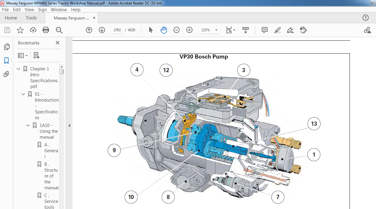

PLEASE NOTE:
- This is the SAME MANUAL used by the dealerships to diagnose your vehicle
- No waiting for couriers / posts as this is a PDF manual and you can download it within 2 minutes time once you make the payment.
- Your payment is all safe and the delivery of the manual is INSTANT – You will be taken to the DOWNLOAD PAGE.
- So have no hesitations whatsoever and write to us about any queries you may have : heydownloadss @gmail.com


