

Manitowoc Grove Crane TM 890 Superstructure Operator’s Manual SN 72977 – PDF DOWNLOAD
FILE DETAILS:
Manitowoc Grove Crane TM 890 Superstructure Operator’s Manual SN 72977 – PDF DOWNLOAD
Language : English
Pages : 216
Downloadable : Yes
File Type : PDF
DESCRIPTION:
Manitowoc Grove Crane TM 890 Superstructure Operator’s Manual SN 72977 – PDF DOWNLOAD
FOREWORD:
- This manual has been compiled to assist you in properly operating and
maintaining your Grove Crane. - Before placing the crane in service, take time to thoroughly familiarize
yourself with the contents of this manual. After all sections have been read
and understood, retain the manual for future reference in a readily accessible
location. - The Grove Crane has been designed for maximum performance with minimum
maintenance. With proper care, years of trouble-free service can be expected. - Constant improvement and engineering progress makes i necessary that we
reserve the right to make specification and equipment changes without
notice, - Engine operating procedures and routine maintenance procedures are supplied
in a separate manual with each crane, and should be referred to for detailed
information. - Information in this manual does not replace federal, state, or local regulations,
safety codes, or insurance requirements. - Any reference to PAT in this manual is to be used for general information
only. For detailed operating instructions of the PAT System, refer to the
PAT Operator’s Handbook. - Changes from the first printing of this manual that have been made in the
text are marked by a vertical bar ( 11 on the margin of the page opposite the
change. - In the event some text is removed, and is not replaced with new or changed
material. a deletion arrow is used where the text was deleted. - In the event there is a change in an illustration, a hand with a pointing finger
will be used to point out where the change occurred. - A CHANGE RECORD page is included as page iv herein. ft is intended that
the recipient of the CHANGE RECORD update as each change is received by
him.
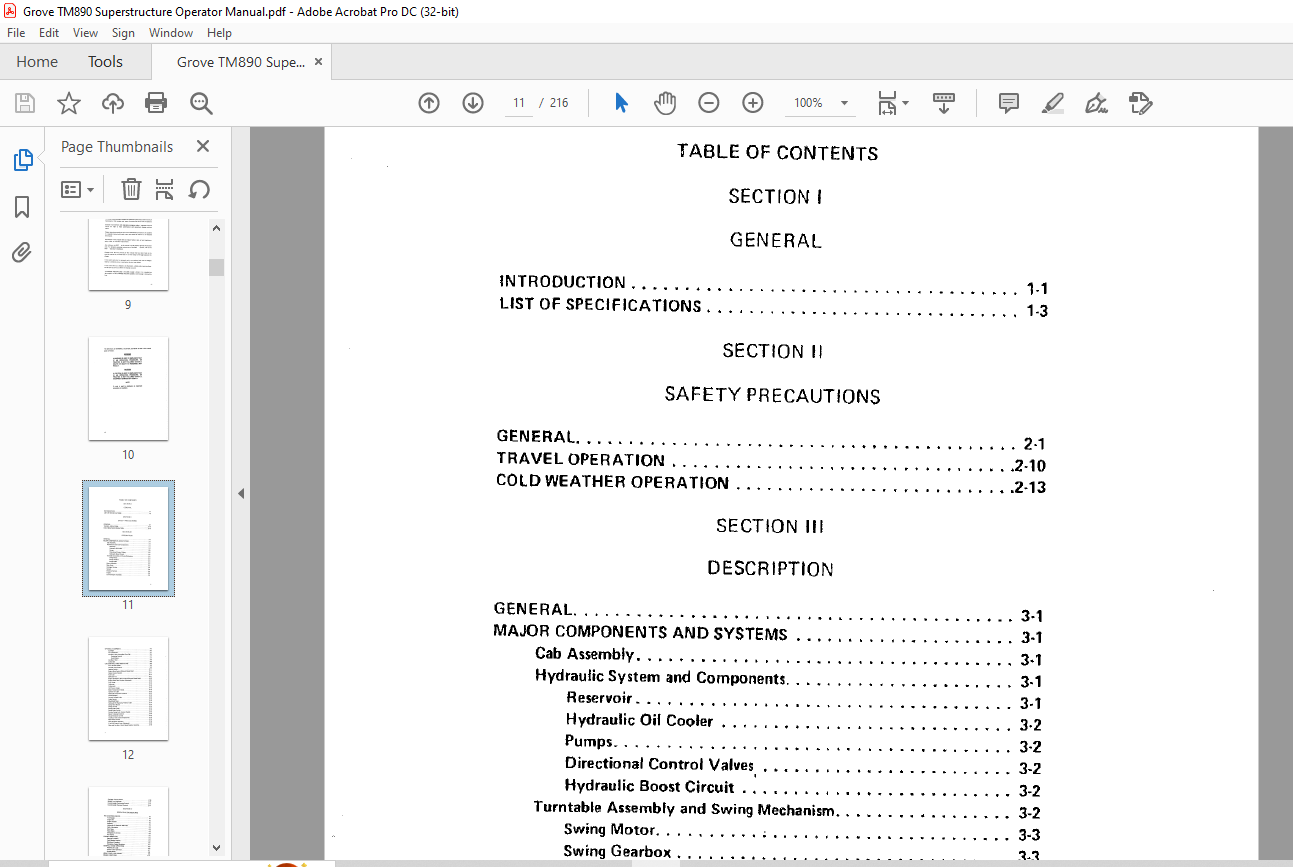
TABLE OF CONTENTS:
Manitowoc Grove Crane TM 890 Superstructure Operator’s Manual SN 72977 – PDF DOWNLOAD
GENERAL
INTRODUCTION 1- 1
LIST OF SPECIFICATIONS 1-3
SECTION II
SAFETY PRECAUTIONS
GENERAL 2-1
TRAVEL OPERATION 2-10
COLD WEATHER OPERATION 2-13
SECTION Ill
DESCRIPTION
GENERAL 3-1
MAJOR COMPONENTS AND SYSTEMS 3-1
Cab Assembly 3-1
Hydraulic System and Components 3-1
Reservoir 3-1
Hydraulic Oil Cooler 3-2
Pumps 3-2
Directional Control Valves 3-2
Hydraulic Boost Circuit 3-2
Turntable Assembly and Swing Mechanism 3-2
Swing Motor , 3-3
Swing Gearbox 3-3
Swing Brake 3-3
Boom Assembly 3-3
Main Hoist : 3-3
Outrigger System 3-4
Swivels 3-4
Electrical System 3-4
Engine 3-5
Counterweight Assembly 3-5
ix
OPTIONAL EQUIPMENT 3-5
Spotlight 3 5
Air Conditioner 3 5
Auxiliary Hoist Controlled Free-Fall 3 5
Operating Control 3 7
Hoist Brakes 3 7
Auxiliary Hoist 3-8
Lattice Jib 3-8
CAB CONTROLS AND INDICATORS 3-8
Foot Throttle Pedal 3-8
Throttle Lock Control 3-8
Ignition Switch · 3-11
Engine Stop Control (Detroit Diesel Only) 3-11
Heater Control Switch 3-11
Fuel Tank 3-11
Defroster Fan 3·11
Engine Emergency Stop Control (Detroit Diesel Only) 3·12
Engine Quick Start System (Optional) 3-12
Fuel Gauge 3·12
Voltmeter 3-12
Tachometer 3-12
Oil Pressure Gauge , , , 3-13
Water Temperature Gauge 3-13
Ignition On Light 3-13
Hydraulic Pump Drive Control 3-13
Cab Domelight 3-13
Control Console Light 3-13
Lights Switch , 3· 13
Windshield Wiper 3-14
Hydraulic Oil Bypassing Filterls) Light 3-14
Swing Horn Button , 3-14
Swing Control 3-14
Swing Brake Pedal 3-14
Swing Brake Switch 3-15
Positive Swing Lock Control Handle 3-15
Boom Telescope Controls 3-15
Boom Elevation Control 3-15
Auxiliary Hoist Control (Optional) 3-16
Main Hoist Control 3-16
Hoist Rotation Indicator 3-16
Free-Fall Control Lever (Optional) 3·16
Main and Auxiliary Hoists Speed Selector Switches 3-16
X
_, ,
Outrigger Control Panels , 3-16
Bubble Level Indicator 3-17
Counterweight Positioning Control , 3 17
Counterweight Removal Controls 3-17
SECTION IV
OPERATING PROCEDURES
PRE-STARTING CHECKS , 4·1
Fuel Supply 4 1
Engine Oil 4-1
Engine Coolant 4-1
Batteries 4-1
Hydraulic Oil Reservoir and Filter 4-1
Daily Lubrication 4-1
Wire Rope 4-2
Hook Block 4-2
Swingaway Extension 4-2
Air Cleaner 4-2
ENGINE OPERATION 4-2
Starting Procedure 4-3
Cold Weather Starting 4-4
Shutdown Procedure 4-5
Emergency Engine Shutdown 4-5
GENERAL CRANE OPERATION 4-6
Handling the Load 4,6
Control Lever Operation 4- 7
Preloed Check , 4-8
USING YOUR LOAO CHART 4-9
CRANE FUNCTIONS 4·11
Setting the Outriggers 4-11
Stowing the Outriggers 4-13
Swinging the Boom 4-15
Elevating and Lowering the Boom 4-16
Elevating the Boom 4-16
Lowering the Boom 4-16
Foot Control 4-17
Emergency Boom Operating Procedures 4-17
Telescoping the Boom 4-18
E,ctending the Boom 4-18
Retracting the Boom 4-19
CHANGE 1 · 9122181 xi I
Power Pinned Fly Section 4-19
Extend 4-19
Retrec:t 4-21
Lowering and Railing the Cable 4-22
Lowering the Cable ;4-23
Railing the Cable 4-23
Hoist Speed Range Selection 4 23
Counterwtigtlt Operatiofl 4-24
Extending the Count-eight 4 24
Reuec:ting thti Count- ight 4-24
OPTIONAL EQUIPMENT OPERATION 4-25
Setting the Center Front Stabilizer 4-25
Stowing the Center Front Stabilizer 4-26
ControUlld Fr Fall 4-27
Operating the Hoist in the Controlled Fr F1II Mode 4-27
Suggested Procedures for Opemon 4-28
Back Preuure 4-28
Engine Quick Stan System 4 29
Air Conditioner 4-29
SECTION V
OPERATIONAL AIDS
GENERAL 5-1
PAT LOAD MOMENT INDICATING ILMIISYSTEM 5-1
CONTROL LEVER LOCKOUT CIRCUIT 5-1
SECTION VI
LUBRICATION
GENERAL 6-1
LUBRICANTS 6-1
Hydraulic Oil Recommendations 6-4
Viscosity 6-4
Arctic Conditions 6-6
Antiwear Additives 6-6
LUBRICATION POINTS 6-6
WIRE ROPE LUBRICATION , 6 14
xii
SECTION VII
SET-UP AND INSTALLATION PROCECURES
GENERAL 7-1
INSTALLING CABLE ON HOIST ORUM 7-1
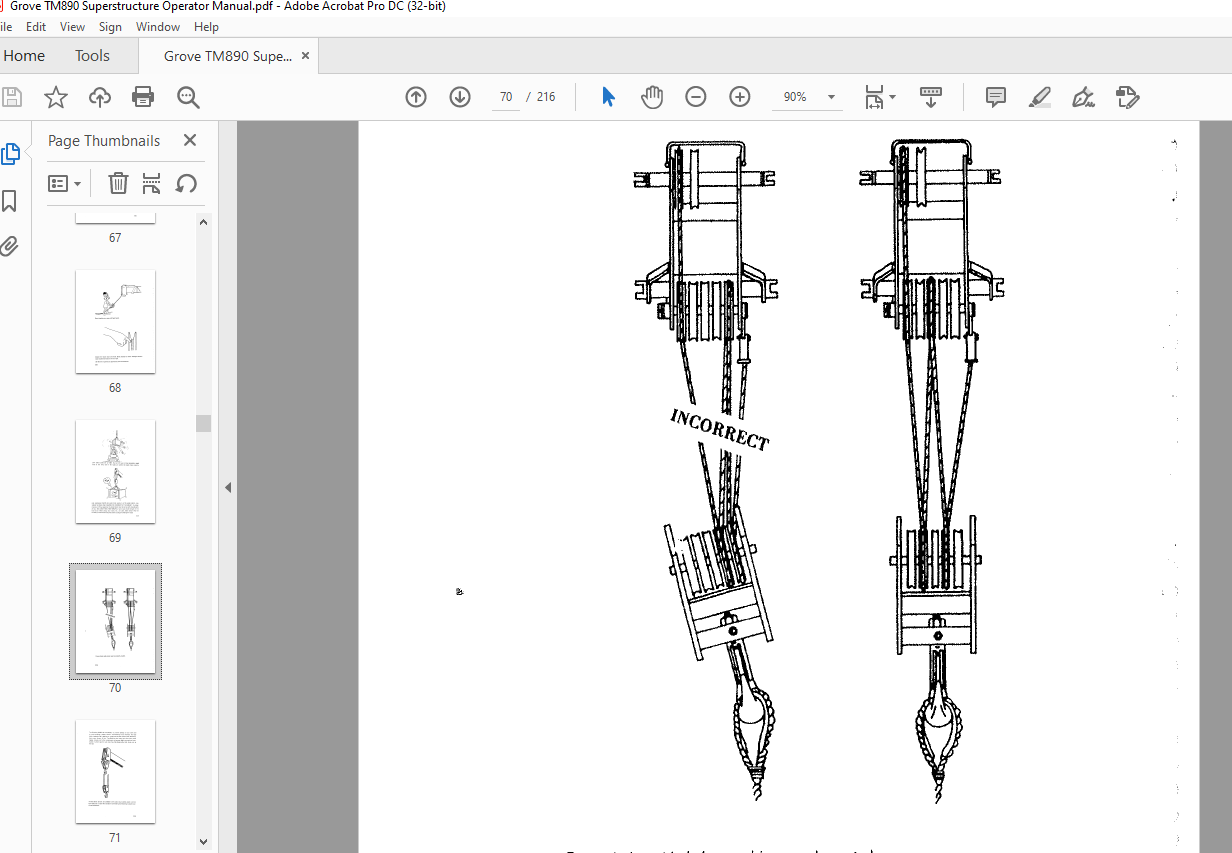
CABLE REEVING 7-2
Repositioning the Inner Idler Sheave 7-4
Single Part Reeving 7-4
Over the Main Boom Nose With the Auxiliary
Boom Nose (Rooster Sheave) 7-4
Over the Main Boom Nose Without the Auxiliary
Boom Nose (Rooster Sheave) 7-7
Multi-Part Reeving 7-9
ERECTING AND STOWING THE 32-FOOT (9 75 M)
SWINGAWAY EXTENSION 7-9
Erecting 7-9
Stowing 7-14
ERECTING AND STOWING THE MULTI-SECTION LATTICE
JIB AND MAST 7-16
Erecting the 46-Foot (14 0 m) Jib 7-16
Stowing the 46-Foot (14 0 m) Jib 7-22
Swinging the Boom 7-26
Elevating and Lowering the Boom 7-27
Elevating the Boom 7-27
Lowering the Boom 7-27
Erecting the 60, 74, and/or 88-Foot (18 3, 22 6,
and/or 26 8 ml Jibs 7-28
Stowing the 60, 74, and/or 88-Foot (18,3, 22 6,
and/or 26 B m) Jibs 7-29
REMOVING AND INSTALLING THE COUNTERWEIGHT 7-29
Removal 7-29
Installation 7-34
TRAILING BOOM SET-UP · ················ -7 ·36 1
Operating Mode to the Trailing Mode 7-36
Trailing Mode to the Operating Mode 7-40
IMAGES PREVIEW OF THE MANUAL:

VIDEO PREVIEW OF THE MANUAL:
PLEASE NOTE:
- This is not a physical manual but a digital manual – meaning no physical copy will be couriered to you. The manual can be yours in the next 2 mins as once you make the payment, you will be directed to the download page IMMEDIATELY.
- This is the same manual used by the dealers inorder to diagnose your vehicle of its faults.
- Require some other service manual or have any queries: please WRITE to us at [email protected]
S.V


