

Linkbelt 160X4 Hydraulic Excavator Service Manual WLSM1607-04LX – PDF DOWNLOAD
FILE DETAILS:
Linkbelt 160X4 Hydraulic Excavator Service Manual WLSM1607-04LX – PDF DOWNLOAD
Language : English
Pages : 2087
Downloadable : Yes
File Type : PDF
Size: 147 MB
IMAGES PREVIEW OF THE MANUAL:
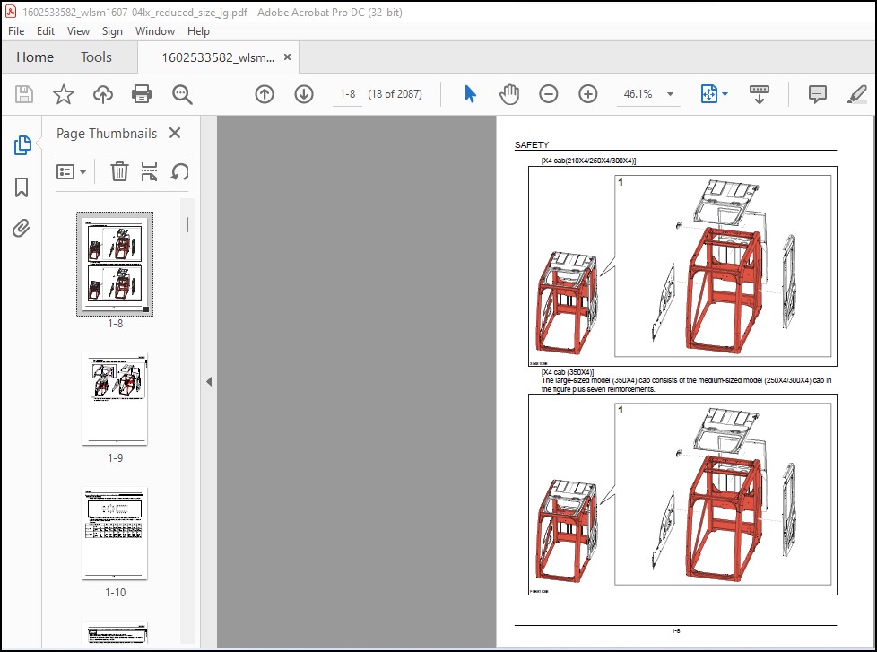

TABLE OF CONTENTS:
Linkbelt 160X4 Hydraulic Excavator Service Manual WLSM1607-04LX – PDF DOWNLOAD
SAFETY 1-1 19389787-1en
Safety, general information and standard torque data 1-2 38637039-0en
General Information 1-3 78709558-3en
Standard Torque Data For Cap Screws And Nuts 1-10 85783483-0en
Protection of Electric/Electronics System During Charging or Welding 1-11 25067536-0en
A LOWER 2-1 71777125-1en
Main Equipment Table 2-3 78443383-0en
Main Equipment Structure and Operation Explanation 2-5 71646005-0en
Port Diagram 2-19 89929564-0en
Basic Functions 2-20 28190417-0en
Removal and Installation of Track 2-22 60049824-0en
Removal and Installation of Roller 2-27 43752628-0en
Removal and Installation of Drive Sprocket 2-44 33101343-6en
Removal and Installation of Take-up Roller 2-47 58088989-2en
Assembly and Disassembly of Take-up Roller 2-49 47665483-7en
Removal and Installation of Grease Cylinder 2-57 83612405-4en
Assembly and Disassembly of Tension Shock Absorber 2-59 97862528-3en
Removal and Installation of Center Joint 2-62 44185736-0en
Assembly and Disassembly of Center Joint 2-66 65948269-3en
Removal and Installation of Travel Motor 2-73 29771973-4en
Assembly and Disassembly of Travel Motor 2-78 51874242-3en
Maintenance Standards 2-130 16266917-1en
Pressure Measurement and Adjustment Procedures 2-138 83246188-1en
Drain Volume Measurement Procedures 2-139 72272769-0en
Air Bleed Procedure 2-141 76863098-0en
B C SWING UNIT, COUNTERWEIGHT 3-1 97410031-1en
Main Equipment Table 3-2 78443383-0en
Main Equipment Structure and Operation Explanation 3-3 71646005-0en
Port Diagram 3-9 89929564-0en
Basic Functions 3-10 28190417-0en
Removal and Installation of Swing Unit 3-13 85170104-0en
Assembly and Disassembly of Swing Motor 3-17 73934145-0en
Assembly and Disassembly of Swing Reduction Gear 3-38 61287321-0en
Removal and Installation of Counterweight 3-41 36414707-0en
Pressure Measurement and Adjustment Procedures 3-44 83246188-1en
Drain Volume Measurement Procedures 3-45 72272769-0en
Air Bleed Procedure 3-46 76863098-0en
H ENGINE 4-1 53979139-1en
Main Equipment Table 4-8 78443383-0en
Basic Functions 4-9 28190417-0en
Primary specifications 4-62 41348197-0en
Function, Structure, Operation 4-64 92793947-1en
Function, structure, operation (SCR) 4-113 27929211-1en
SCR Control System Inspection 4-142 78058558-1en
Explanation of SCR Operation 4-143 95238910-2en
Diagnosis for Each Symptom 4-145 21805842-1en
Diagnosis for Each Symptom 4-150 35120819-0en
Functional Inspection 4-160 69663730-0en
Removal and Installation of Engine Assembly 4-169 38504961-1en
Removal and Installation of Fuel Cooler, Engine Intercooler, Radiator, and Oil
Cooler 4-175
78628914-1en
Removal and Installation of Turbo Charger 4-184 42858817-3en
Removal and Installation of EGR Valve (if equipped) 4-188 32547506-1en
Removal and Installation of EGR Cooler 4-189 76253396-0en
Removal and Installation of Engine Hood 4-194 79727064-2en
Removal and Installation of SCR 4-196 22249628-1en
Removal and Installation of SCR Catalyst 4-199 35256315-0en
Removal and Installation of Cylinder Head Cover 4-206 78412812-0en
Removal and Installation of Cylinder Block 4-245 75278091-0en
Lubrication System 4-293 70203119-0en
Cooling System 4-343 69949934-0en
Induction System 4-350 35136601-1en
Exhaust System 4-351 48741304-1en
Aux Emission Control Devices System 4-356 40110763-1en
Removal and Installation of Exhaust Manifold 4-363 78382524-0en
Removal and Installation of Fuel Tank 4-369 65150023-0en
Removal and Installation of Urea Pump 4-373 76020255-1en
Removal and Installation of Urea Solution Tank 4-375 98954852-3en
Removal and Installation of Fuel Supply Pump 4-377 18906180-0en
Removal and Installation of Common Rail Assembly 4-390 24718817-0en
Removal and Installation of Injector 4-393 31274146-0en
Removal and Installation of Crankshaft 4-399 41515482-0en
Removal and Installation of Piston and Connecting Rod 4-449 71546782-0en
Removal and Installation of Camshaft 4-496 78651166-0en
Removal and Installation of Flywheel 4-504 16909059-0en
Removal and Installation of Crankshaft front oil seal 4-507 94513586-0en
Removal and Installation of Crankshaft rear oil seal 4-512 34080281-0en
Removal and Installation of Timing Chain 4-517 41603930-0en
Removal and Installation of Timing Gear Train 4-526 53164075-0en
Removal and Installation of Timing Gear Case 4-542 47755787-0en
Removal and Installation of Inlet Manifold 4-576 88563247-0en
Removal and Installation of Rocker Arm Shaft 4-581 97916536-0en
Removal and Inspection of Valve Stem Oil Seal and Valve Spring 4-594 87650229-0en
Removal and installation of Intake Throttle Valve 4-605 84766342-1en
Removal and Installation of Starter Motor 4-606 47128180-3en
Removal and Installation of Alternator 4-609 47829873-0en
Removal and Installation of Glow Plug 4-614 45292928-0en
Removal and Installation of Suction Control Valve 4-616 74896489-0en
Removal and installation of Fuel Filter 4-618 70596988-1en
Removal and installation of Relief Valve 4-621 41397729-1en
Contents
2
Removal and installation of Fuel Filter Element 4-622 28551690-1en
Removal and installation of Fuel temperature sensor 4-626 13119135-1en
Removal and installation of Pressure limiter 4-639 91840001-1en
Removal and installation of Fuel pressure sensor 4-640 54310813-1en
Removal and Installation of Fuel filter pressure 4-641 41943855-1en
Removal and Installation of Engine coolant temperature sensor 4-642 72826315-1en
Removal and Installation of CKP sensor 4-644 92654264-1en
Removal and Installation of CMP sensor 4-645 11296113-1en
Removal and Installation of Oil pressure sensor 4-646 71303987-1en
Removal and installation of Boost Sensor 4-648 99996908-0en
Removal and installation of Boost Temperature Sensor 4-649 98544793-0en
Removal and installation of Turbocharger control solenoid 4-650 99346476-1en
Removal and Installation of IMT sensor 4-652 42362214-1en
Removal and installation of MAF and IAT sensor 4-653 91296734-1en
Removal and installation of Charge Air Cooler Temperature Sensor 1 4-654 94613570-1en
Sampling Procedure 4-655 38464543-0en
Removal and Installation of Exhaust gas temperature sensor 4-656 58748167-1en
Removal and installation of EGR Gas Temperature Sensor 1 4-658 85535450-1en
Removal and installation of EGR Gas Temperature Sensor 2 4-659 21977257-1en
Removal and installation of NOx Sensor 4-661 96418407-1en
Removal and installation of EGR Gas Temperature Sensor 3 4-664 17113595-0en
Removal and installation of DEF Sensor 4-666 55572903-1en
Engine-related Diagnostic Trouble Code List 4-667 99630402-2en
Engine-side Trouble 4-676 16577120-0en
Data Reference Values 4-857 49437404-1en
J HYDRAULIC EQUIPMENT (PUMP, OPERATION SYSTEM VALVE) 5-1 68276312-1en
Main Equipment Table 5-5 78443383-0en
Basic Functions 5-11 28190417-0en
Port Diagram 5-30 89929564-0en
Hydraulic Pump 5-46 71826868-0en
Control Valve 5-71 56107455-0en
4 Stack Solenoid Valve Operation Explanation 5-111 67705302-0en
Upper Pilot Valve (remote control valve) 5-113 25350181-0en
Travel Pilot Valve (remote control valve) 5-118 39613125-0en
Cushion Valve 5-124 11949795-0en
Selector Valve (2-way) 5-129 32379090-0en
Direction Valve (3-direction) 5-132 30102944-0en
3 Stack Proportional Valve (for pilot) 5-135 66937395-0en
Electromagnetic Relief Valve 5-139 64662087-0en
Removal and Installation of Hydraulic Reservoir 5-143 26789161-0en
Removal and Installation of Hydraulic Pump 5-147 18643784-1en
Removal and Installation of Pump coupling 5-152 34418244-1en
Removal and Installation of Control Valve 5-154 25222268-1en
Removal and Installation of Travel Remote Control Valve 5-158 39592336-0en
Removal and Installation of Operation Remote Control Valve 5-162 14130834-4en
Removal and Installation of 4 Stack Solenoid 5-170 89670842-5en
Removal and Installation of Cushion Valve 5-174 92880177-0en
Procedures for Assembly and Disassembly of Hydraulic Pump Main Unit 5-177 59889726-0en
Pump Main Unit Maintenance Standards 5-184 54580195-0en
Regulator Maintenance Standards 5-195 86103035-0en
Procedures for Assembly and Disassembly of Control Valve 5-210 17697175-0en
Procedures for Assembly and Disassembly of Operation Remote Control Valve 5-234 80887250-1en
Procedures for Assembly and Disassembly of Travel Remote Control Valve 5-245 23581849-0en
Assembly and Disassembly of Cushion Valve 5-258 38410900-0en
Pressure Measurement and Adjustment Procedures 5-262 83246188-1en
Hydraulic Pump Flow Measurement Procedures 5-280 62052930-0en
Air Bleed Procedure 5-284 76863098-0en
Sampling Procedure 5-285 38464543-0en
Hydraulic Equipment Layout 5-286 81702821-0en
Overall View 5-287 98709019-0en
N CAB 6-1 25744330-1en
Removal and Installation of Operator’s Seat 6-2 29749369-0en
Removal and Installation of Cab Assembly 6-3 44037089-5en
Removal and Installation of Wiper 6-8 25113440-4en
Removal and Installation of Cab Front Glass 6-9 51688380-4en
Removal and Installation of Right-side Window Glass 6-11 20957683-1en
Removal and Installation of Door (Upper) Sash Glass 6-16 88900412-1en
Window Lock Adjustment Procedures 6-21 90955407-5en
Removal and Installation of Housing Guardrail 6-23 76560728-0en
Tightening torque 6-24 29026121-4en
R ELECTRICAL PARTS 7-1 18400544-1en
Basic Functions 7-3 28190417-0en
Service Support 7-26 30914595-0en
Connection Connector Pin Layout 7-139 81470562-0en
Sequence Circuit Diagram 7-141 95593007-0en
Electrical Equipment Layout Diagram 7-157 82458022-0en
Removal and Installation of Wiper Controller 7-191 51905383-4en
Removal and Installation of Wiper Motor 7-192 60222373-1en
Removal and Installation of ECM 7-194 37149170-1en
Removal and Installation of Main Controller 7-195 35550813-0en
Removal and Installation of DCU 7-196 63452717-0en
Removal and Installation of Monitor 7-197 51691250-2en
Removal and Installation of Rear View Camera 7-198 83779341-0en
Removal and Installation of Side Camera (right) 7-199 43100996-0en
Removal and Installation of Side Camera (Left) 7-200 35072143-0en
Removal and Installation of FVM Controller 7-201 75916970-1en
How to Set FVM 7-202 33847448-0en
Air Conditioner Overall Diagram 7-206 70666574-0en
Assembly and Disassembly of Unit 7-244 80491730-0en
Removal and Installation of Compressor 7-247 20570260-4en
Removal and Installation of Condenser 7-248 75115462-5en
Removal and Installation of Receiver Dryer 7-250 67605030-3en
Work Precautions 7-252 23051033-6en
V ATTACHMENTS 8-1 84181484-1en
Main Equipment Table 8-3 78443383-0en
Maintenance Standards 8-4 16266917-1en
Removal and Installation of Bucket Cylinder 8-15 55586201-3en
Removal and Installation of Arm Cylinder 8-18 34302078-0en
Removal and Installation of Boom Cylinder 8-23 84721499-0en
Procedures for Operation/Assembly and Disassembly of Hydraulic Cylinder 8-28 71081947-0en
HBCV 8-60 83156430-0en
Port Diagram 8-76 89929564-0en
Air Bleed Procedure 8-77 76863098-0en
Removal and Installation of HBCV 8-79 95886020-0en
Removal and Installation of Arm HBCV 8-80 30385026-0en
Removal and Installation of Boom HBCV 8-81 52617503-0en
Removal and Installation of Bucket 8-83 32138276-1en
Removal and Installation of Bucket Link 8-85 92026381-0en
Removal and Installation of Arm 8-87 35510946-4en
Removal and Installation of Boom 8-89 61860364-0en
Z OTHER 9-1 68145258-1en
Change from Type 6 9-4 58609717-1en
Specifications 9-12 53620175-0en
Arm Dimension 9-17 31180251-0en
Main Unit Weight 9-21 12343363-0en
Bolt Size and Torque Table 9-24 30335582-1en
Overall View 9-29 34508823-0en
WORK RANGE DIAGRAM 9-31 20473064-1en
New Machine Performance Judgment Table 9-36 72039816-1en
FLUIDS AND LUBRICANTS 9-45 18850575-0en
Main-Unit-related Diagnostic Trouble Code List 9-46 70292507-4en
Main Unit-side Trouble 9-49 14139955-0en
List of special tools 9-160 95642836-0en
Paint Colors 9-196 87135229-0en
Abbreviation 9-198 55975748-0en
DESCRIPTION:
Linkbelt 160X4 Hydraulic Excavator Service Manual WLSM1607-04LX – PDF DOWNLOAD
General Information:
Cleaning
Clean the metal parts with a cleaning fluid or steamer that meets standards. (except for the bearing) After cleaning the parts, let them dry well and inject oil into all parts. Inject oil into the bearing after letting it dry.
Inspection
When disassembling parts, inspect all the parts. Replace any worn or damaged parts. Inspect them thoroughly to prevent early failures.
Bearing
If the bearing is loose, replace it. Install the bearing after air drying it.
Needle bearing
When inserting the needle bearing, be careful not to scratch it.
Inject grease into the location where the needle bearing is to be inserted.
Gear
Check for any wear or damage.
Oil seals, O-rings, gaskets
Always install new oil seals, O-rings, and gaskets. Inject grease into the locations where oil seals and O-rings are to be inserted.
Shaft
Check for any wear or damage. Check the oil seal on the bearing and damaged shaft.
Service parts
Install genuine LBX Link-Belt service parts. When ordering parts, see the parts catalog that has genuine LBX Link-Belt part numbers listed. Any failures caused by installing a nongenuine part are not covered by the warranty.
Lubrication (fuel, hydraulic oil)
- Use oils from specified manufacturers or the ones specified in the operator’s manual or Service Manual.
- Any failures caused by using other fuel or hydraulic oil than specified are not covered by the warranty.
VIDEO PREVIEW OF THE MANUAL:
PLEASE NOTE:
- This is the same manual used by the DEALERSHIPS to SERVICE your vehicle.
- The manual can be all yours – Once payment is complete, you will be taken to the download page from where you can download the manual. All in 2-5 minutes time!!
- Need any other service / repair / parts manual, please feel free to contact us at heydownloadss @gmail.com . We may surprise you with a nice offer
S.V


