

Liebherr PR 736 1736 05_G8.0, 1736 4F G8.0 (USA CAN) Crawler Dozer Operator’s Manual 16834 – PDF DOWNLOAD
FILE DETAILS:
Liebherr PR 736 1736 05_G8.0, 1736 4F G8.0 (USA CAN) Crawler Dozer Operator’s Manual 16834 – PDF DOWNLOAD
Language : English
Pages : 374
Downloadable : Yes
File Type : PDF
Size: 80.9 MB
DESCRIPTION:
Liebherr PR 736 1736 05_G8.0, 1736 4F G8.0 (USA CAN) Crawler Dozer Operator’s Manual 16834 – PDF DOWNLOAD
Product ID
Manufacturer : Liebherr-Werk Telfs GmbH
Type : PR 736
Type no. : 1736 05_G8.0, 1736 4F G8.0 (USA/ CAN)
From Serial no. : 16834
Preface:
This operator’s manual has been written for the operator and for the maintenance
staff of the machine.
It contains the descriptions for:
– Chapter 1 “Product description”
– Chapter 2 “Safety instructions”
– Chapter 3 “Control, operation”
– Chapter 4 “Malfunctions”
– Chapter 5 “Maintenance”
The operator’s manual must be read and used carefully by all persons who carry
out work with or on the machine before putting the machine into service for the first
time and later, at regular intervals.
Work with or on the machine includes, for example:
Operation including set up, troubleshooting during work procedure, disposal of production wastes, care, disposal of service and auxiliary materials.
Service including maintenance, inspection and repair work
Transport or loading the machine
This allows the machine operator to familiarize himself with the machine more
easily and prevent malfunctions due to improper operation.
Observation of the operator’s manual by maintenance staff:
– increases reliability in use
– extends the service life of your machine
– reduces repair costs and downtime
- The operator’s manual belongs with the machine. Make sure that a copy is
always readily available in the operator’s cab. - The operator’s manual should be supplemented with instructions for accident
prevention and environmental protection based on existing national regulations.
In addition to the operator’s manual and legally binding regulations on accident
prevention which apply in the user country and at point of use, authorized specialist
rules for safe and correct working procedures are also to be observed. - These operator’s manual contains all required information for control, operation
and maintenance of your machine. - Some illustrations in this operator’s manual may depict details and working devices
which differ to your machine. - In some illustrations, protective devices and covers have been removed in the
interests of better presentation. - Improvements, which are always being incorporated into our machines, may result
in changes to your machine which are not yet indicated in this operator’s manual.
If you need additional explanations or instructions, please don’t hesitate to contact
the Technical Documentation and Service Department.
TABLE OF CONTENTS:
Liebherr PR 736 1736 05_G8.0, 1736 4F G8.0 (USA CAN) Crawler Dozer Operator’s Manual 16834 – PDF DOWNLOAD
1 Product description
1.1.1 Overview of the complete machine
Technical data
1.2.1 Vibrations
1.2.2 CO2 emissions of the diesel engine
1.2.3 Sound level
1.2.4 Maximum operating mass
1.2.5 Diesel engine
1.2.6 Travel drive and control system
1.2.7 Working hydraulics
1.2.8 Operator’s cab
1.2.9 Travel gear
1.2.10 Pull force
1.2.11 Basic machine dimensions
1.2.12 Front equipment
1.2.13 Rear equipment
Warranty conditions
1.3.1 Additional information
1.3.2 Warranty declaration, emission limits, warranty rights and obligations
1.3.3 Warranty coverage from manufacturer
1.3.4 Warranty obligations of the owner
1.3.5 Warranty
1.3.6 Warranty parts
1.3.7 Exclusions
Tightening torques
1.4.1 Preload values and tightening torques for screws with standard and fine
metric thread according to DIN ISO 261
1.4.2 Tightening torque for cutting edges, end bits and adapters
2 Safety guidelines, signs 39
2.1 Designation of warning notes 39
2.1.1 Additional rules and guidelines 40
2.2 Symbols in the operator’s manual 40
2.3 Proper use 40
2.3.1 Laws, rules, guidelines and safety regulations 40
2.3.2 Intended use 40
2.3.3 Foreseeable misuse 41
2.3.4 Hazard zone of the machine 42
2.3.5 Operating conditions 43
2.3.6 Disposal 44
2.4 Description of personnel 45
2.4.1 Personal protective equipment 45
2.4.2 Requirements for personnel 45
2.4.3 Operator 46
2.4.4 Operator 46
2.4.5 Maintenance staff 47
2.4.6 Guide 48
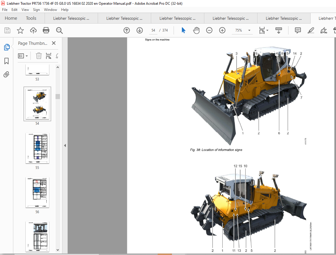
2.5 Signs on the machine 48
2.5.1 Safety signs 49
2.5.2 Information signs 53
2.5.3 Identification plates 58
2.6 Safety instructions 59
2.6.1 General safety instructions 59
2.6.2 Safety guidelines for crushing and burn prevention 60
2.6.3 Safety guidelines for fire and explosion prevention 60
2.6.4 Safety instructions for machine start up 61
2.6.5 Safety guidelines for start up 61
2.6.6 Safety guidelines for working 61 0 “0 ‘ “‘
2.6.7 Safety guidelines for turning machine off 63
2.6.8 Safety instructions for transporting machine 63 ~
2.6.9 Safety instructions for towing machine 63 “~’
2.6.10 Safety instructions for maintenance 64
2.6.11 Safety guidelines for welding work on machine 66
2.6.12 Safety guidelines for working on attachment 66
2.6.13 Safety guidelines for loading machine with a crane 67
2.6.14 Safety notes for maintenance of hydraulic hoses and hose lines 67
2.6.15 Safety guidelines for maintenance work on machines with hydro accumulators
2.6.16 Roll over protection (ROPS) and falling object protection (FOPS) 68
2.6.17 Equipment and attachment parts 69
2.6.18 Protection from vibrations 69
2.6.19 See and be seen 70
2.6.20 Safety notes for Diesel engines with electronic control units 72
2.6.21 Safety notes for working on Common Rail System of Diesel engines 72
3 Control, operation 75
3.1.1 Overview of operator’s cab
3.1.2 Control elements in the operator’s cab
3.1.3 Exhaust gas treatment
Display
3.2.1 Display
3.2.2 Service codes menu
3.2.3 Status symbols
3.2.4 Warning symbols
3.2.5 Start page menu
3.2.6 Camera (option) menu
3.2.7 Diesel engine menu
3.2.8 Operator’s cab menu
3.2.9 Function settings menu
3.2.10 Information menu
3.2.11 System settings menu
Operation
3.3.1 Battery main switch
3.3.2 Entry and exit lighting (option)
3.3.3 Entering and exiting machine
3.3.4 Emergency exit
3.3.5 Door lock
3.3.6 Standard operator’s seat
3.3.7 Operator’s seat with pneumatic comfort suspension 120
3.3.8 Premium operator’s seat (option) 127
3.3.9 Premium ISRI (option) operator’s seat 134
3.3.10 Safety belt 140
3.3.11 Adjusting armrest, control lever and footrest 143
3.3.12 Heating and air conditioning unit 145
3.3.13 Auxiliary heater (option) 148
3.3.14 Sliding window 150
3.3.15 Interior lighting of operator’s cab 150
3.3.16 Interior mirror 151
3.3.17 Windscreen wiper and windscreen washer system 151
3.3.18 Storage net for documentation 153
3.3.19 Turning on the engine compartment lighting 153
3.3.20 Acoustic reversing warning device (option) 153
3.3.21 Fire extinguisher (option) 155
3.3.22 Beacon (option) 155
3.3.23 LiDAT (option) 155
3.3.24 Electronic immobiliser (option) 155
3.4 Operation 158
3.4.1 Operating machine on a daily basis 158
3.4.2 Using the machine at low or high ambient temperatures 168
3.4.3 Starting the diesel engine 168
3.4.4 Travel mode 172
3.4.5 Driving 180
3.4.6 Braking 184
3.4.7 Using the emergency stop button to stop and continue the operation 187
3.4.8 Taking machine out of service 187
3.4.10 Working with working attachment 191 0 “0 ‘ “‘
3.4.11 Working with optional working attachment 208 ~
3.4.12 Regenerating diesel particle filter 210 ~
3.4.13 Free Grade and Definition Grade
3.4.14 Machine control system
3.5 Work methods 227
3.5.1 Grading 227
Contents
3.5.2 Fine grading 228
3.5.3 Using several machines simultaneously 229
3.5.4 Digging and banking up trenches 230
3.5.5 Land clearing 231
3.5.6 Ripping 233
3. 6 Install and remove the attachment 235
3.6.1 Installation guidelines for installation and removal of working attachment
3.6.2 Installing the bearing shells of the working attachment
3.6.3 Installing and removing push frame with straight blade
3.6.4 Installing and removing the 6-way blade
3.7 Transport
3.7.1 Transporting the machine by truck or rail
3.7.2 Loading the machine with a crane
3.8 Emergency operations
3.8.1 Emergency mode function
3.8.2 Towing the machine
3.8.3 Jump start procedure
Operating problems
4.1 Problems – Cause – Remedy
4.1.1 Diesel engine
4.1.2 Hydraulic system
4.1.3 Travel gear
4.1.4 Electrical system
4.1.5 Heating
4.1.6 Working attachment
4.1.7 Electronic immobiliser (option)
4.2 Problem remedy
4.2.1 Changing fuses
Maintenance
5.1 Maintenance and inspection schedule
5.2 Fill quantities, lubrication schedule
Recommended lubricants
Recommended fuel and operating fluids
Operator’s manual
5.2.3 Lubrication chart 302
5.2.4 Symbols in the lubrication chart 304
Lubricants and fuels 305
5.3.1 General information about lubricants and fuels 305
5.3.2 Diesel fuels 306
5.3.3 Engine oils 306
5.3.4 Coolant 308
5.3.5 Diesel exhaust fluids 310
5.3.6 Hydraulic oils 310
5.3.7 Lube oils for travel gearbox 312
5.3.8 Oil for duo cone (slipring) seal Travel gear 313
5.3.9 Oil for axle bearing 313
5.3.10 Grease and other lubricants 313
5.3.11 Oil for hinges and joints 315
Take oil samples 316
5.4.1 Oil samples and oil analysis 316
Preparatory maintenance tasks 320
5.5.1 Safety instructions for maintenance 320
5.5.2 Maintenance position 320
Overall machine 324
5.6.1 Lubricating all lube points according to lubrication chart 324
5.6.2 Checking and changing the windscreen wiper blade 324
5.6.3 Carrying out the maintenance and inspection for the optional equipment
in the scope of delivery according to the manufacturer’s operator’s
manual or manufacturer’s data 325
Diesel engine 326
5.7.1 Diesel engine: checking oil level 326
5.7.2 Checking the diesel engine configuration and the belly pan for contamination
and cleaning them 327
Cooling system 329
5.8.1 Checking the coolant level 329
5.8.2 Cleaning the cooling system 331
Fuel system 336
5.9.1 Notes for working on the fuel system 336
5.9.2 Draining fuel pre-filter condensation 336
5.9.3 Fuel tank: draining condensation and sediment 337
5.9.4 Emptying and cleaning the fuel tank 338
5.10 Air filter system 342
5.10.1 Replacing the air filter 342
5.10.2 Air filter: checking dust discharge 345
5.11 Diesel particle filter 346
5.12 Hydraulic system 347
5.12.1 Checking oil level in the hydraulic tank and topping up oil 347
5.13 Electrical system 350
5.13.1 Lighting: checking for correct function 350
5.14 Heater, ventilation, air conditioning system 352
5.14.1 Inspection of the air conditioning system by HVAC specialist staff 352
5.14.2 Checking the condenser 352
5.15 Drive gear 353
5.15.1 Travel gearbox: checking the condition 353
5.15.2 Checking oil level in duo cone (slip ring) area 353
5.16 Track components 355
5.16.1 Checking that the nuts and bolts of the travel gear components are
firmly seated 355
5.16.2 Checking the track tension and adjusting, if necessary 356
5.17 Working attachment 360
5.17.1 Checking the cutting edges, corners and ripper teeth for wear 360
5.17.2 Checking the mounting screws and pin retainers of the working attachment
for tight seating 360
5.17.3 Removing and installing the ripper tooth tips 360
5.18 Cleaning the machine 365
5.18.1 Wet cleaning machine 365
5.19 Preservation tasks 367
5.19.1 Protecting the piston rods 367
5.19.2 Taking the machine out of service 367
Index 369
IMAGES PREVIEW OF THE MANUAL:


VIDEO PREVIEW OF THE MANUAL:
PLEASE NOTE:
- This is the SAME manual used by the dealers to troubleshoot any faults in your vehicle. This can be yours in 2 minutes after the payment is made.
- Contact us at [email protected] should you have any queries before your purchase or that you need any other service / repair / parts operators manual.
S.V


