

Liebherr PR 726-1793_05_G8.0 18370 PR 726-1793_4F_G8.0 18370 Crawler Dozer Service Manual – PDF DOWNLOAD
FILE DETAILS:
Liebherr PR 726-1793_05_G8.0 18370 PR 726-1793_4F_G8.0 18370 Crawler Dozer Service Manual – PDF DOWNLOAD
Language : English
Pages : 796
Downloadable : Yes
File Type : PDF
Size: 172 MB
DESCRIPTION:
Liebherr PR 726-1793_05_G8.0 18370 PR 726-1793_4F_G8.0 18370 Crawler Dozer Service Manual – PDF DOWNLOAD
Foreword:
Notes for the user:
This Service manual is intended for trained specialist staff in the Liebherr organization
and its dealers.
The Service manual provides specific knowledge for the maintenance of Liebherr construction machinery. Basic technical knowledge of electrics, hydraulics, mechanics and Diesel engine technology are not detailed in this Service manual. A
subject-based, qualified training is therefore necessary. Liebherr recommends participation on the Liebherr Training program for construction machinery.
In this Service manual you find information about:
– Special tools
– Technical data
– Maintenance intervals and maintenance tasks
– Adjustment procedure
– Design and functional descriptions
– Removal and installation tasks
– Wiring diagrams, hydraulic schematics and technical drawings
For information relating to control and operation refer to the operator’s manual. For information relating to spare parts refer to the Spare parts catalog. Observe the locally applicable accident prevention regulations.
Safety instructions
General safety instructions
1. Please familiarize yourself with operator’s manual before putting machine
into service.
Make sure that you have obtained, read and understand any additional instructions
relating to special accessories for machine.
2. Only explicitly authorized personnel may operate, maintain or repair the
machine.
Observe the permissible minimum legal age limit!
3. Use only trained or instructed personnel, clearly determine the responsibility of
the personnel for operation, set up, maintenance and repairs.
4. Determine machine operator responsibility (also in regards to traffic regulations)
and allow him to refuse unsafe instructions from third persons.
5. Do not allow any person either still to be trained or already in training to
operate or work on machine unless under constant supervision and guidance
of an experienced instructor or operator.
6. Check and observe any person working or operating machine at least periodically
if they observe safety instructions and guidelines given in operator’s
manual.
7. Always wear proper work clothing when operating or working on machine.
Avoid wearing rings, watches, ties, scarves, open jackets, loose clothing, etc.
There is a danger of injury, as they can get stuck or be pulled in.
Prescribed for specific tasks: safety glasses, safety shoes, safety helmet, work
gloves, reflective vest, ear protection, …
8. Consult supervisor at jobsite for special safety instructions and regulations.
9. When entering and exiting the machine, maintain three-point contact.
10. When entering or exiting, never use joysticks as handholds.
This could trigger inadvertent movement of machine and cause serious accidents.
11. Never jump off the machine. When climbing on or off machine, use intended
steps, ladders and catwalks and handles. Use both hands for support and face
machine.
12. Keep steps, ladders and handles free of oil, grease, mud, snow and ice. These
precautions will minimize the danger of slipping, stumbling or falling.
13. Make yourself familiar with emergency exit.
14. If no other instructions are given, proceed as follows for maintenance and
repair work.
Procedure:
• Park the machine on solid and level ground. .1l
• Bring all control levers to neutral position. i;i
• Set parking switch to park position. ~ ..,.1
• Turn engine off and pull ignition key. 0
• Actuate control levers several times to relieve pressure in servo lines. 1..,,
• Bring all control levers to neutral position.
15. Before working on hydraulic circuit, with engine turned off and with ignition key I~ii
in contact position, move all pilot controls uoysticks and pedals) in both direc- 1;i
tions to relieve servo pressure and remaining back pressures in working ~
circuits. Then release internal hydraulic tank pressure. ~
16. Before leaving operator’s seat, switch parking switch to Park position. ‘”‘
17. Secure all loose parts on machine.
18. Never operate a machine without a complete walk around inspection. Check if
all warning signs are on the machine and if they are all legible.
19. Observe all signs with danger and safety instructions.
TABLE OF CONTENTS:
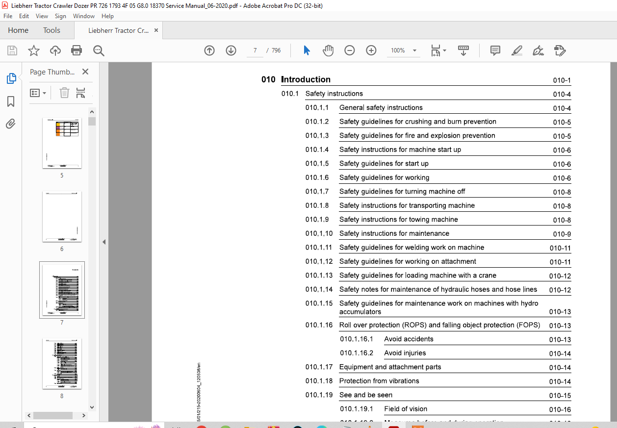
010 Introduction 010-1
010.1 Safety instructions 010-4
010.1.1 General safety instructions 010-4
010.1.2 Safety guidelines for crushing and burn prevention 010-5
010.1.3 Safety guidelines for fire and explosion prevention 010-5
010.1.4 Safety instructions for machine start up 010-6
010.1.5 Safety guidelines for start up 010-6
010.1.6 Safety guidelines for working 010-6
010.1.7 Safety guidelines for turning machine off 010-8
010.1.8 Safety instructions for transporting machine 010-8
010.1.9 Safety instructions for towing machine 010-8
010.1.10 Safety instructions for maintenance 010-9
010.1.11 Safety guidelines for welding work on machine 010-11
010.1.12 Safety guidelines for working on attachment 010-11
010.1.13 Safety guidelines for loading machine with a crane 010-12
010.1.14 Safety notes for maintenance of hydraulic hoses and hose lines 010-12
010.1.15 Safety guidelines for maintenance work on machines with hydro
accumulators 010-13
010.1.16 Roll over protection (ROPS) and falling object protection (FOPS) 010-13
010.1.16.1 Avoid accidents 010-13
010.1.16.2 Avoid injuries 010-14
1.,l 010.1.17 Equipment and attachment parts 010-14
1 010.1.18 Protection from vibrations 010-14
0 “00 ‘ 010.1.19 See and be seen 010-15 “0 ‘
010.1.19.1 Field of vision 010-16
010.1.19.2 Measures before and during operation 010-16
010.1.20 Safety notes for Diesel engines with electronic control units 010-17 ~
010.1.21 Safety notes for working on Common Rail System of Diesel engine!{)10-17
010.2 Special tools for maintenance and repair work 010-19
010.2.1 Tools – Diesel engine 010-19
010.2.2 Tools – Hydraulic system 010-21
010.2.3 Tools – Hydraulic cylinder 010-25
010.2.4 Tools – Electrical system 010-26
010.2.5 Tools – Travel gearbox 010-29
010.2.6 Tools – Travel gear 010-30
010.2.7 Tension unit tools 010-31
010.2.8 Tools – Oscillating axle frame 010-31
010.2.9 Tools – Operator’s cab 010-32
010.2.10 Tools – Diesel exhaust fluid system 010-32
010.2.11 Assistance system tools 010-33
Standards and specifications 010-34
010.3.1 Preload values and tightening torques for screws with standard and
fine metric thread according to DIN ISO 261 010-34
010.3.1.1 Scope of application and purpose 010-34
010.3.1.2 Further applicable documentation 010-34
010.3.1.3 Changes and descriptions 010-35
010.3.1.4 Tightening values 010-35
010.3.1.5 Flanges and half flanges for high pressure (standard
62) 010-41
010.3.1.6 Half flange for low pressure (standard 61) 010-41
010.3.1.7 Tightening torques for cutting edges, end bits and
adapters 010-41
010.3.2 Installation specifications 010-42
010.3.2.1 Duo cone slipring seals 010-42
010.3.3 Tapping bores 010-44
010.3.3.1 Tapping bores of metric ISO standard threads 010-44
010.3.3.2 Tapping bores of metric ISO fine threads 010-46
010.3.4 Conversion tables 010-49
Conservation guidelines 010-50
General 010-50
Taking the machine out of service for an unknown duration 010-50
Shut down of the machine 010-51
010.4.3.1 Shut down for up to 2 months 010-51
010.4.3.2 Shut down for up to 12 months 010-52
010.4.3.3 Shut down for longer than 12 months 010-53
Return to operation
010.4.4.1
010.4.4.2
010.4.4.3
010.5 Repair welding
After a shut down of 2 months
After a shut down of 12 months
After shut down of longer than 12 months
010.5.1 Preparation of cracked part
010.5.1 Preparation of a weld
010.5.1 Treatment of electrodes
010.5.1 Welding technique
010.5.1 Reinforcement of welding seam
010.5.1 General use of reinforcement sheeting
010.6 Hydraulic symbols
010.7 Electrical symbols
010.8 Material weights
Form of sheeting
Thickness of sheeting
Material quality of sheeting
Application of reinforcement sheeting
Welding the reinforcement sheeting
Selection of correct welding electrodes
Electrode selection
Steel chart
Welding additives chart
020 Technical data 020-1
020.1 Drive group 020-3
020.1.1 Diesel engine
PR726-1793-4F-G8. 0/18370; PR726-1793-05-G8. 0/18370; 020-3
020.2 Cooling system 020-5
020.2.1 Gear pump for cooling circuit
PR726-1793-4F-G8. 0/18370; PR726-1793-05-G8. 0/18370; 020-5
020.2.2 Fan drive gear motor for water, charge air and hydraulic oil cooler
PR726-1793-4F-G8. 0/18370; PR726-1793-05-G8. 0/18370; 020-5
020.3 Working hydraulics 020-6
PR726-1793_ 4F G8.0,
PR726-1793_05_G8.0 / 18370
020.3.1 Working hydraulics regulating pump
PR726-1793-4F-G8. 0/18370; PR726-1793-05-G8. 0/18370; 020-6
020.3.2 Proportional control valve block
PR726-1793-4F-G8. 0/18370; PR726-1793-05-G8. 0/18370; 020-6
020.3.3 Lift cylinder
PR726-1793-4F-G8. 0/18370; PR726-1793-05-G8. 0/18370; 020-6
020.3.4 Tilt cylinder
PR726-1793-4F-G8. 0/18370; PR726-1793-05-G8. 0/18370; 020-7
020.4 Travel hydraulics 020-9
020.4.1 Variable displacement motor
PR726-1793-4F-G8. 0/18370; PR726-1793-05-G8. 0/18370; 020-9
020.5 Electrical system 020-10
020.5.1 Batteries Installation
PR726-1793-4F-G8. 0/18370; PR726-1793-05-G8. 0/18370; 020-10
020.6 Travel gear, axles, tyres, drive shafts 020-11
020.6.1 Undercarriage frame
PR726-1793-4F-G8. 0/18370; PR726-1793-05-G8. 0/18370; 020-11
020.6.2 Idler
PR726-1793-4F-G8. 0/18370; PR726-1793-05-G8. 0/18370; 020-11
020.6.3 Tension unit
PR726-1793-4F-G8. 0/18370; PR726-1793-05-G8. 0/18370; 020-11
020.6.4 Track roller
PR726-1793-4F-G8. 0/18370; PR726-1793-05-G8. 0/18370; 020-11
020.6.5 Track chain
PR726-1793-4F-G8. 0/18370; PR726-1793-05-G8. 0/18370; 020-12
020.6.6 Sprocket
PR726-1793-4F-G8. 0/18370; PR726-1793-05-G8. 0/18370; 020-12
020.7 Working attachment 020-14
020.7.1 Ripper
PR726-1793-4F-G8. 0/18370; PR726-1793-05-G8. 0/18370; 020-14
Maintenance 030-1
Maintenance and inspection schedule 030-9
Fill quantities, lubrication schedule 030-14
030.2.1 Recommended lubricants
PR726-1793-05-G8. 0/18370; 030-14
030.2.2 Recommended fuel and operating fluids
PR726-1793-05-G8. 0/18370; 030-15
030.2.3 Lubrication schedule
PR726-1793-4F-G8. 0/18370; PR726-1793-05-G8. 0/18370; 030-15
Lubricants and fuels
030.3.1 General information about lubricants and fuels
030.3.1.1 General Information
030.3.1.2 General questions
030.3.1.3 Safety data sheets
030.3.1.4 Technical data sheets 030-18
030.3.1.5 Specific Liebherr standards 030-18
Diesel fuels
PR726-1793-05-G8. 0/18370; 030-19
030.3.2.1 Liebherr recommendation 030-19
Engine oils
PR726-1793-05-G8. 0/18370; 030-20
030.3.3.1 Liebherr recommendations for stage IV/tier 4f and
stage V diesel engines 030-20
030.3.3.2 Liebherr recommendation for other emission stages 030-20
030.3.3.3 Minimum quality requirement 030-21
030.3.3.4 Aggravating circumstances 030-21
Coolant
PR726-1793-05-G8. 0/18370; 030-22
030.3.4.1 Requirements for water used 030-22
030.3.4.2 Corrosion inhibitor 030-22
030.3.4.2 Liebherr recommendation 030-22
030.3.4.2 Anti-freeze and corrosion protection agent 030-22
030.3.4.2 Liebherr recommendation 030-22
030.3.4.2 Minimum quality requirement 030-23
Diesel exhaust fluids
PR726-1793-05-G8. 0/18370; 030-23
030.3.5.1 Liebherr recommendation 030-23
030.3.5.2 Minimum quality requirement 030-23
Hydraulic oils
PR726-1793-05-G8. 0/18370; 030-23
030.3.6.1 Liebherr recommendation 030-23
030.3.6.2 Minimum quality requirement 030-24
030.3.6.3 Oil analysis 030-24
030.3.6.4 Filter change 030-24
030.3.6.5 Oil change 030-25
Lube oils for travel gearbox
PR726-1793-05-G8. 0/18370; 030-25
030.3.7.1 Quality 030-25
030.3.7.2 Viscosity 030-26
030.3.7.3 Oil change 030-26
Oil for duo cone (slipring) seal Travel gear
PR726-1793-4F-G8. 0/18370; PR726-1793-05-G8. 0/18370; 030-26
030.3.9 Grease and other lubricants
PR726-1793-05-G8. 0/18370; 030-27
030.3.10 Oil for hinges and joints
PR726-1793-4F-G8. 0/18370; PR726-1793-05-G8. 0/18370; 030-28
030.3.11 Oil for axle bearing
PR726-1793-4F-G8. 0/18370; PR726-1793-05-G8. 0/18370; 030-29
Maintenance tasks 030-30
Safety instructions for maintenance
PR726-1793-4F-G8. 0/18370; PR726-1793-05-G8. 0/18370; 030-30
Maintenance – preparations 030-30
030.4.2.1 Maintenance position
PR726-1793-05-G8. 0/18370; 030-30
030.4.2.2 Lifting operator’s cab
PR726-1793-05-G8. 0/18370; 030-33
030.4.2.3 Lowering the operator’s cab
PR726-1793-05-G8. 0/18370; 030-37
Overall machine 030-40
030.4.3.1 Checking the machine for external damage, correct
maintenance and proper condition
PR726-1793-4F-G8. 0/18370; PR726-1793-05-
G8.0/18370; 030-40
030.4.3.2 Lubricating all lube points according to lubrication
chart
PR726-1793-4F-G8. 0/18370; PR726-1793-05-
G8.0/18370; 030-40
030.4.3.3 Checking and changing the windscreen wiper blade
PR726-1793-05-G8. 0/18370; 030-41
030.4.3.4 Carrying out the maintenance and inspection for the
optional equipment in the scope of delivery according
to the manufacturer’s operator’s manual or manufacturer’s
data
PR726-1793-05-G8. 0/18370; 030-41
030.4.3.5 Oil samples and oil analysis
PR726-1793-05-G8. 0/18370; 030-42
030.4.3.6 Wet cleaning machine
PR726-1793-05-G8. 0/18370; 030-45
030.4.3.7 Protecting the piston rods
PR726-1793-4F-G8. 0/18370; PR726-1793-05-
G8.0/18370; 030-47
030.4.3.8 Taking the machine out of service
PR726-1793-4F-G8. 0/18370; PR726-1793-05-
G8.0/18370; 030-47
Drive group 030-47
030.4.4.1 Diesel engine: checking oil level
PR726-1793-05-G8. 0/18370; 030-47
030.4.4.2 Changing engine oil
PR726-1793-05-G8. 0/18370; 030-49
030.4.4.3 Changing oil filter
PR726-1793-05-G8. 0/18370; 030-51
030.4.4.4 Checking the diesel engine configuration and the
belly pan for contamination and cleaning them
PR726-1793-05-G8. 0/18370; 030-52
030.4.4.5 Checking the ribbed V-belt and adjusting it if
necessary
PR726-1793-05-G8. 0/18370; 030-53
030.4.4.6 Checking and replacing belt drive
PR726-1793-05-G8. 0/18370; 030-55
030.4.4.7 Checking diesel engine configuration for leaks and
condition
PR726-1793-05-G8. 0/18370; 030-57
030.4.4.8 Checking suction lines and exhaust lines for damage,
leaks and tight seating
PR726-1793-05-G8. 0/18370; 030-58
030.4.4.9 Diesel engine: checking electrical system
PR726-1793-05-G8. 0/18370; 030-59
030.4.4.10 Changing oil separator filter cartridge
PR726-1793-05-G8. 0/18370; 030-60
030.4.4.11 Checking and changing the heater flange
PR726-1793-05-G8. 0/18370; 030-61
030.4.4.12 Checking the engine mount, oil pan and engine
brackets for tight seating
PR726-1793-05-G8. 0/18370; 030-65
030.4.4.13 Checking speed according to adjustment checklist
PR726-1793-05-G8. 0/18370; 030-65
030.4.4.14 Checking valve clearance
PR726-1793-05-G8. 0/18370; 030-65
030.4.4.15 Checking intake system and exhaust treatment
system for leaks and hose installation for abrasion
PR726-1793-05-G8. 0/18370; 030-67
030.4.4.16 Checking the tightening torque of profile clamp
PR726-1793-05-G8. 0/18370; 030-67
030.4.4.17 Notes for working on the fuel system
PR726-1793-05-G8. 0/18370; 030-68
030.4.4.18 Draining fuel pre-filter condensation
PR726-1793-05-G8. 0/18370; 030-68
030.4.4.19 Fuel tank: draining condensation and sediment
PR726-1793-05-G8. 0/18370; 030-69
030.4.4.20 Changing the fuel pre-filter
PR726-1793-05-G8. 0/18370; 030-70
030.4.4.21 Changing fuel fine filter
PR726-1793-05-G8. 0/18370; 030-73
030.4.4.22 Checking fuel system for leaks and condition
PR726-1793-05-G8. 0/18370; 030-75
030.4.4.23 Emptying and cleaning the fuel tank
PR726-1793-05-G8. 0/18370; 030-75
030.4.4.24 Venting fuel pre-filter and fuel system
PR726-1793-05-G8. 0/18370; 030-78
030.4.4.25 Replacing the air filter
PR726-1793-05-G8. 0/18370; 030-81
030.4.4.26 Air filter: checking dust discharge
PR726-1793-05-G8. 0/18370; 030-84
030.4.4.27 Diesel particle filter: changing filter module
PR726-1793-05-G8. 0/18370; 030-84
Cooling system 030-93
030.4.5.1 Checking the coolant level
PR726-1793-05-G8. 0/18370; 030-93
030.4.5.2 Cleaning the cooling system
PR726-1793-05-G8. 0/18370; 030-96
030.4.5.3 Checking cooling system for leaks and damage
PR726-1793-05-G8. 0/18370; 030-96
030.4.5.4 Checking anti-freeze concentration of the coolant
PR726-1793-05-G8. 0/18370; 030-97
030.4.5.5 Changing coolant
PR726-1793-05-G8. 0/18370; 030-104
Travel hydraulics 030-107
030.4.6.1 Changing supply circuit filter cartridge
PR726-1793-05-G8. 0/18370; 030-107
Hydraulic components 030-111
030.4.7.1 Checking oil level in the hydraulic tank and topping
up oil
PR726-1793-05-G8. 0/18370; 030-111
030.4.7.2 Cleaning magnetic rod of the hydraulic tank
PR726-1793-05-G8. 0/18370; 030-114
030.4.7.3 Checking hydraulic system for function and leaks
PR726-1793-05-G8. 0/18370; 030-116
030.4.7.4 Changing hydraulic oil
PR726-1793-05-G8. 0/18370; 030-116
030.4.7.5 Checking and adjusting hydraulic pressures as per
adjustment checklist
PR726-1793-05-G8. 0/18370; 030-119
030.4.7.6 Changing return filter cartridge
PR726-1793-05-G8. 0/18370; 030-119
Electrical system 030-120
030.4.8.1 Lighting: checking for correct function
PR726-1793-05-G8. 0/18370; 030-120
030.4.8.2 Checking the batteries
PR726-1793-05-G8. 0/18370; 030-121
030.4.8.3 Checking cable routings and connections
PR726-1793-05-G8. 0/18370; 030-124
030.4.8.4 Checking and adjusting travel drive control system as
per adjustment checklist
PR726-1793-05-G8. 0/18370; 030-124
Travel gearbox 030-124
030.4.9.1 Travel gearbox: checking the condition
PR726-1793-4F-G8. 0/18370; PR726-1793-05-
G8.0/18370; 030-124
030.4.9.2 Checking oil level and cleaning magnetic plug
PR726-1793-05-G8. 0/18370; 030-124
030.4.9.3 Travel gearbox: changing oil and cleaning magnetic
plugs
PR726-1793-05-G8. 0/18370; 030-125
030.4.9.4 Checking oil level in duo cone (slip ring) area
PR726-1793-05-G8. 0/18370; 030-127
030.4.9.5 Flushing duo cone (slip ring) area and replacing oil in
this area
PR726-1793-05-G8. 0/18370; 030-129
Travel gear, axles, tyres, drive shafts 030-134
030.4.10.1 Checking that the nuts and bolts of the travel gear
components are firmly seated
PR726-1793-05-G8. 0/18370; 030-134
030.4.10.2 Checking the carrier rollers, track rollers and idlers
for tightness
PR726-1793-4F-G8. 0/18370; PR726-1793-05-
G8.0/18370; 030-136
030.4.10.3 Checking idler guides and adjusting, if necessary
PR726-1793-05-G8. 0/18370; 030-136
030.4.10.4 Checking the track tension and adjusting, if
necessary
PR726-1793-05-G8. 0/18370; 030-140
030.4.10.5 Checking the travel gear wear
PR726-1793-4F-G8. 0/18370; PR726-1793-05-
G8.0/18370; 030-143
030.4.10.6 Axle bearing: checking oil level and topping up
PR726-1793-05-G8. 0/18370; 030-143
Working attachment 030-144
030.4.11.1 Checking the cutting edges, corners and ripper teeth
for wear
PR726-1793-4F-G8. 0/18370; PR726-1793-05-
G8.0/18370; 030-144
Service manual
030.4.11.2 Checking the bearing points of the working attachment
for play and wear
030.4.11.3 Checking the mounting screws and pin retainers of
the working attachment for tight seating
PR726-1793-4F-G8. 0/18370; PR726-1793-05-
G8. 0/18370; 030-146
030.4.11.4 Removing and installing the ripper tooth tips
PR726-1793-05-G8. 0/18370; 030-14 7
030.4.12 Operator’s cab, heating, air conditioning
030.4.12.1 Checking heating and air conditioning for function
and leaks
030-150
PR726-1793-05-G8.0/18370; 030-150
030.4.12.2 Cleaning recirculated air fresh air filter and changing
it if necessary
PR726-1793-05-G8. 0/18370; 030-151
030.4.12.3 Inspection of the air conditioning system by HVAC
specialist staff
PR726-1793-05-G8. 0/18370; 030-152
030.4.12.4 Checking the condenser
PR726-1793-05-G8.0/18370; 030-152
030.5 Testing and adjustment checklist
PR726-1793-4F-G8. 0/18370; PR726-1793-05-G8. 0/18370;
030.5.1 Adjustment checklist
030.5.2 Track Components Check List
Test report
Wear data
030.6 Check and adjustment tasks
030.6.1 Safety instructions
PR726-1793-4F-G8. 0/18370; PR726-1793-05-G8. 0/18370;
030.6.2 Overall machine
Preparations for adjustment procedures
PR726-1793-4F-G8. 0/18370; PR726-1793-05-
G8. 0/18370;
Visual inspection and maintenance
PR726-1793-4F-G8. 0/18370; PR726-1793-05-
G8. 0/18370;
Bringing machine to operating temperature
030.6.2.3 Various procedures can be selected for reaching the
operating temperature:
PR726-1793-4F-G8. 0/18370; PR726-1793-05-
G8. 0/18370; 030-178
Drive group 030-180
030.6.3.1 Engine speed controller of diesel engine – determining
adjustment range
PR726-1793-4F-G8. 0/18370; PR726-1793-05-
G8.0/18370; 030-180
Cooling system 030-183
030.6.4.1 Checking the stand-by pressure for the fan control
PR726-1793-4F-G8. 0/18370; PR726-1793-05-
G8.0/18370; 030-183
030.6.4.2 Checking pressure relief valve – fan motor and fan
control
PR726-1793-4F-G8. 0/18370; PR726-1793-05-
G8.0/18370; 030-184
Working hydraulics 030-191
030.6.5.1 Checking the standby pressure
PR726-1793-4F-G8. 0/18370; PR726-1793-05-
G8.0/18370; 030-191
030.6.5.2 Checking operating pressure for working hydraulics
PR726-1793-4F-G8. 0/18370; PR726-1793-05-
G8.0/18370; 030-192
030.6.5.3 Checking the primary pressure relief valve on the
control valve block
PR726-1793-4F-G8. 0/18370; PR726-1793-05-
G8.0/18370; 030-193
030.6.5.4 Checking LS pressure relief valve on the control
valve block
PR726-1793-4F-G8. 0/18370; PR726-1793-05-
G8.0/18370; 030-195
030.6.5.5 Checking the secondary pressure relief valves on the
control valve block
PR726-1793-4F-G8. 0/18370; PR726-1793-05-
G8.0/18370; 030-196
030.6.5.6 Checking pressure cut off at working hydraulics regulating
pump
PR726-1793-4F-G8. 0/18370; PR726-1793-05-
G8.0/18370; 030-198
030.6.5.7 Checking nitrogen fill in the hydro accumulator
PR726-1793-4F-G8. 0/18370; PR726-1793-05-
G8.0/18370; 030-199
Travel hydraulics 030-200
030.6.6.1 Checking supply pressure of variable displacement
pump
PR726-1793-4F-G8. 0/18370; PR726-1793-05-
G8.0/18370; 030-200
030.6.6.2 Checking hydraulic neutral position of variable
displacement pump
PR726-1793-4F-G8. 0/18370; PR726-1793-05-
G8.0/18370; 030-202
030.6.6.3 Checking the pressure limitation for high pressure
PR726-1793-4F-G8. 0/18370; PR726-1793-05-
G8.0/18370; 030-204
030.6.6.4 Checking the pressure regulator
PR726-1793-4F-G8. 0/18370; PR726-1793-05-
G8.0/18370; 030-205
030.6.7 Electrical system 030-208
030.6.7.1 Calibrating the hydrostat
PR726-1793-4F-G8. 0/18370; PR726-1793-05-
G8.0/18370; 030-208
030.6.7.2 Checking travel joystick
PR726-1793-4F-G8. 0/18370; PR726-1793-05-
G8.0/18370; 030-219
030.6.7.3 Calibrating inching brake pedal
PR726-1793-4F-G8. 0/18370; PR726-1793-05-
G8.0/18370; 030-221
030.6.7.4 Brake test
PR726-1793-4F-G8. 0/18370; PR726-1793-05-
G8.0/18370; 030-229
030.6.7.5 Parameter adjustment options
PR726-1793-4F-G8. 0/18370; PR726-1793-05-
G8.0/18370; 030-233
030.6.7.6 Addressing CAN modules
PR726-1793-4F-G8. 0/18370; PR726-1793-05-
G8.0/18370; 030-235
030.6.7.7 Central control (Master5): connecting the Sculi diagnasties
software
PR726-1793-4F-G8. 0/18370; PR726-1793-05-
G8.0/18370; 030-240
030.6.7.8 Central control (Master5): connecting the LiFT function
PR726-1793-4F-G8. 0/18370; PR726-1793-05-
G8.0/18370; 030-243
030.6.7.9 Central control (Master5): software update
PR726-1793-4F-G8. 0/18370; PR726-1793-05-
G8.0/18370; 030-244
030.6.7.10 Central control (Master5): resetting to factory settings
PR726-1793-4F-G8. 0/18370; PR726-1793-05-
G8.0/18370; 030-247
030.6.7.11 Entry and exit lighting – setting the lighting duration
PR726-1793-4F-G8. 0/18370; PR726-1793-05-
G8.0/18370; 030-249
Drive group 040-1
040.1 Diesel engine 040-2
040.1.1 Diesel engine – Full overview
PR726-1793-4F-G8. 0/18370; PR726-1793-05-G8. 0/18370; 040-2
Service manual
040.1.2 Fuel system
Fuel system
PR726-1793-4F-G8. 0/18370; PR726-1793-05-
G8. 0/18370;
Fuel quantity sensor
PR726-1793-4F-G8. 0/18370; PR726-1793-05-
G8. 0/18370;
Fuel filter
PR726-1793-4F-G8. 0/18370; PR726-1793-05-
G8. 0/18370;
Fuel tank
PR726-1793-4F-G8. 0/18370; PR726-1793-05-
G8. 0/18370;
040.1.3 Air filter system
040.1.3.1 Air filter system
PR726-1793-4F-G8. 0/18370; PR726-1793-05-
G8. 0/18370;
040.1.4 Exhaust system
040.1.4.1 Exhaust system – Full overview
PR726-1793-4F-G8. 0/18370; PR726-1793-05-
G8. 0/18370;
040.1.5 Diesel engine mounting
PR726-1793-4F-G8. 0/18370; PR726-1793-05-G8. 0/18370;
040.2 Clutch
PR726-1793-4F-G8. 0/18370; PR726-1793-05-G8. 0/18370;
050 Cooling system
050.1 Complete cooling system
PR726-1793-4F-G8. 0/18370; PR726-1793-05-G8. 0/18370;
050.2 Cooler arrangement
050.2.1 Cambi cooler
PR726-1793-4F-G8. 0/18370; PR726-1793-05-G8. 0/18370; 050-5
050.3 Hydraulic
050.3.1 Gear pump
PR726-1793-4F-G8. 0/18370; PR726-1793-05-G8. 0/18370;
050.3.2 Gear motor
PR726-1793-4F-G8. 0/18370; PR726-1793-05-G8. 0/18370;
060 Working hydraulics
060.1 6-way blade
PR726-1793-4F-G8. 0/18370; PR726-1793-05-G8. 0/18370;
060.2 Regulating pump
PR726-1793_ 4F G8.0,
PR726-1793_05_G8.0 / 18370
060.2.1 Regulating pump – Full overview
PR726-1793-4F-G8. 0/18370; PR726-1793-05-G8. 0/18370;
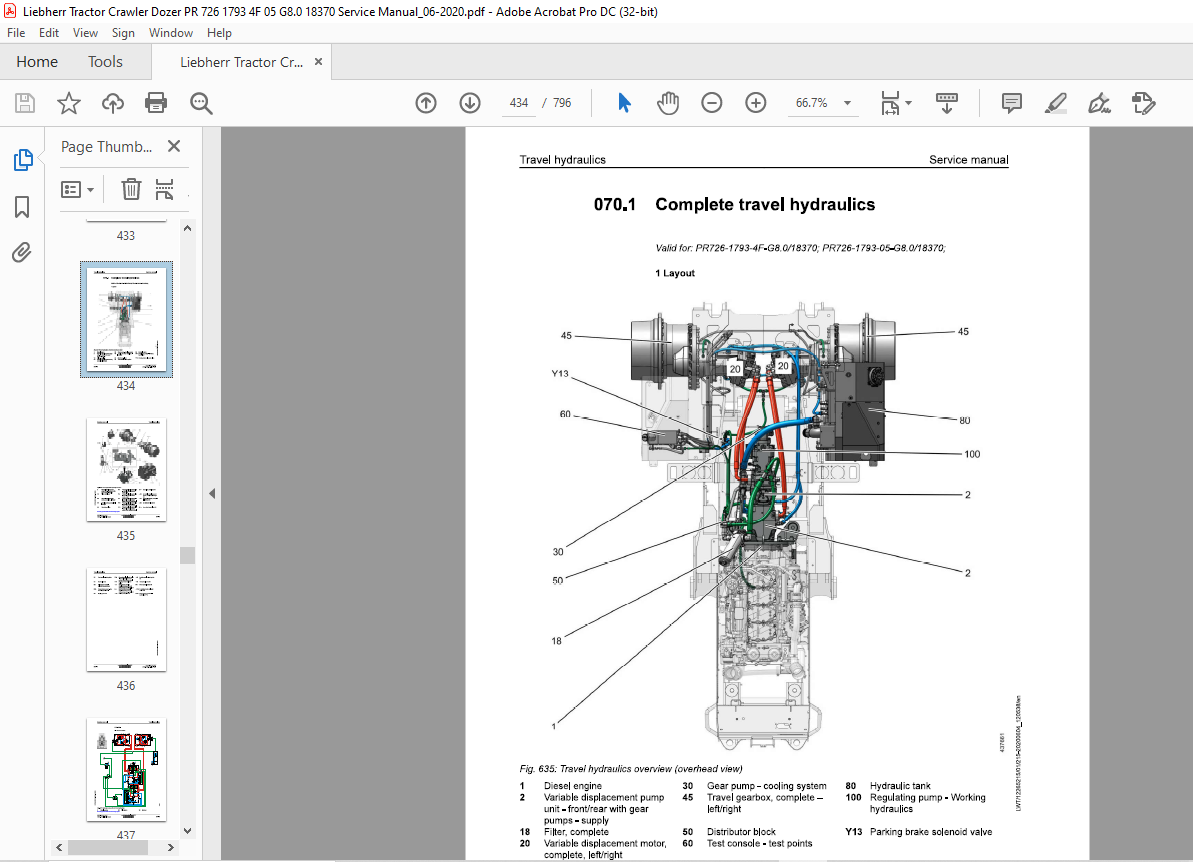
Travel hydraulics 070-1
070.1 Complete travel hydraulics
PR726-1793-4F-G8. 0/18370; PR726-1793-05-G8. 0/18370; 070-2
070.2 Variable displacement pump
PR726-1793-4F-G8. 0/18370; PR726-1793-05-G8. 0/18370; 070-13
070.3 Variable displacement motors 070-19
070.3.1 Variable displacement motors – full overview
PR726-1793-4F-G8. 0/18370; PR726-1793-05-G8. 0/18370; 070-19
Hydraulic components 080-1
080.1 Hydraulic cylinder 080-2
080.1.1 Lift cylinder
PR726-1793-4F-G8. 0/18370; PR726-1793-05-G8. 0/18370; 080-2
080.1.2 Tilt cylinder
PR726-1793-4F-G8. 0/18370; PR726-1793-05-G8. 0/18370; 080-4
080.1.3 Swing cylinder
PR726-1793-4F-G8. 0/18370; PR726-1793-05-G8. 0/18370; 080-6
080.1.4 Ripper cylinder
PR726-1793-4F-G8. 0/18370; PR726-1793-05-G8. 0/18370; 080-8
080.2 Hydraulic tank 080-11
080.2.1 Hydraulic tank
PR726-1793-4F-G8. 0/18370; PR726-1793-05-G8. 0/18370; 080-11
Brake system 100-1
100.1 Inching brake pedal 100-2
100.1.1 Speed reduction pedal
PR726-1793-4F-G8. 0/18370; PR726-1793-05-G8. 0/18370; 100-2
Electrical system 110-1
110.1 Electrical system – Full overview
PR726-1793-4F-G8. 0/18370; PR726-1793-05-G8. 0/18370; 110-3
110.2 Lighting system
PR726-1793-4F-G8. 0/18370; 110-5
110.3 Circuit diagrams
PR726-1793-4F-G8. 0/18370; PR726-1793-05-G8. 0/18370; 110-8
110.4 Electrical components of operator’s cab 110-9
110.4.1 Electrical components in operator’s cab
PR726-1793-4F-G8. 0/18370; PR726-1793-05-G8. 0/18370; 110-9
110.4.2 Central control (Master 105)
PR726-1793-4F-G8. 0/18370; PR726-1793-05-G8. 0/18370; 110-16
110.4.3 Compact control (A 120)
PR726-1793-4F-G8. 0/18370; PR726-1793-05-G8. 0/18370; 110-17
110.4.4 Travel joystick
PR726-1793-4F-G8. 0/18370; PR726-1793-05-G8. 0/18370;
110.4.5 Speed control
PR726-1793-4F-G8. 0/18370; PR726-1793-05-G8. 0/18370;
110.5 Electrical components – Diesel engine
PR726-1793-4F-G8. 0/18370; PR726-1793-05-G8. 0/18370;
110.6 Electrical components – Main frame
PR726-1793-4F-G8. 0/18370; PR726-1793-05-G8. 0/18370;
110. 7 Electrical components Compartments
110.7.1 Battery compartment
PR726-1793-4F-G8. 0/18370; PR726-1793-05-G8. 0/18370;
110.7.2 Fuel tank compartment
PR726-1793-4F-G8. 0/18370; PR726-1793-05-G8. 0/18370;
110.7.3 Central electrical system compartment
PR726-1793-4F-G8. 0/18370; PR726-1793-05-G8. 0/18370;
110.7.4 Hydraulic tank
PR726-1793-4F-G8. 0/18370; PR726-1793-05-G8. 0/18370;
110.8 Display unit
PR726-1793-4F-G8. 0/18370; PR726-1793-05-G8. 0/18370;
110.9 Electrical components LiTU3 (option)
PR726-1793-4F-G8. 0/18370; PR726-1793-05-G8. 0/18370;
110. 10 Electrical components – Assistance systems
110.10.1 Calibrating Free Grade and Definition Grade
PR726-1793-4F-G8. 0/18370; PR726-1793-05-G8. 0/18370;
110. 11 Electrical components of machine control
110.11.1 Electrical components of machine control Trimble
PR726-1793-4F-G8. 0/18370; PR726-1793-05-G8. 0/18370;
110.11.2 Electrical components of machine control Leica
PR726-1793-4F-G8. 0/18370; PR726-1793-05-G8. 0/18370;
110.11.3 Electrical components of machine control Topcon
PR726-1793-4F-G8. 0/18370; PR726-1793-05-G8. 0/18370;
120 Travel gearbox
120.1 Travel gearbox, overall
PR726-1793-4F-G8. 0/18370; PR726-1793-05-G8. 0/18370;
120.2 Brake system
PR726-1793-4F-G8. 0/18370; PR726-1793-05-G8. 0/18370;
120.3 Duo cone slipring seal
PR726-1793-4F-G8. 0/18370; PR726-1793-05-G8. 0/18370;
120.4 External oil supply
PR726-1793_ 4F G8.0,
PR726-1793_05_G8.0 / 18370
PR726-1793-4F-G8. 0/18370; PR726-1793-05-G8. 0/18370;
Travel gear, axles, tyres, drive shafts 130-1
130.1 Travel gear frame 130-3
130.1.1 Support frame
PR726-1793-4F-G8. 0/18370; PR726-1793-05-G8. 0/18370; 130-3
130.2 Idler
PR726-1793-4F-G8. 0/18370; PR726-1793-05-G8. 0/18370; 130-5
130.3 Tension unit
PR726-1793-4F-G8. 0/18370; PR726-1793-05-G8. 0/18370; 130-7
130.4 Tension unit – removal
PR726-1793-4F-G8. 0/18370; PR726-1793-05-G8. 0/18370; 130-9
130.4.1.1 Remove the cover on the track roller frame 130-10
130.4.1.2 Position of tension unit grease nipple 130-11
130.4.1.3 Push the pin in 130-11
130.4.1.4 Removal of cover 130-12
130.4.1.5 Grease nipple with twist guard 130-12
130.4.1.6 Place a mark 130-13
130.4.1.7 Installation of the assembly tool 130-13
130.4.1.8 Adjust the assembly tool 130-14
130.4.1.9 Clamp on the assembly tool 130-14
130.4.1.10 Press in the tension unit 130-16
130.4.1.11 Removal of the tension unit 130-17
130.5 Tension unit – installation
PR726-1793-4F-G8. 0/18370; PR726-1793-05-G8. 0/18370; 130-18
130.5.1.1 Installation 130-18
130.5.1.2 Positioning of left and right travel gear 130-18
130.5.1.3 Press in the tension unit 130-20
130.5.1.4 Venting the tension unit 130-21
130.5.1.5 Installation of cover 130-21
130.5.1.6 Install the cover on the track roller frame 130-22
130.6 Track roller
PR726-1793-4F-G8. 0/18370; PR726-1793-05-G8. 0/18370; 130-23
130.7 Carrier roller
PR726-1793-4F-G8. 0/18370; PR726-1793-05-G8. 0/18370; 130-24
130.8 Function, wear and evaluation
PR726-1793-4F-G8. 0/18370; PR726-1793-05-G8. 0/18370; 130-25
Steel components Basic machine 140-1
140.1 Lift cylinder suspension
PR726-1793-4F-G8. 0/18370; PR726-1793-05-G8. 0/18370;
140.2 Equaliser bar
PR726-1793-4F-G8. 0/18370; PR726-1793-05-G8. 0/18370;
140.3 Push frame (inside)
PR726-1793-4F-G8. 0/18370; PR726-1793-05-G8. 0/18370;
150 Working attachment
150.1 Ripper
PR726-1793-4F-G8. 0/18370; PR726-1793-05-G8. 0/18370;
150.2 Ripper for front equipment, 6-way blade
PR726-1793-4F-G8. 0/18370; PR726-1793-05-G8. 0/18370;
160 Operator’s cab, heating, air conditioning
160.1 Operator’s platform
160.1.1 Operator’s platform installations
PR726-1793-4F-G8. 0/18370; PR726-1793-05-G8. 0/18370;
160.1.2 Operator’s platform bearing
PR726-1793-4F-G8. 0/18370; PR726-1793-05-G8. 0/18370;
160.1.3 Support cylinder
PR726-1793-4F-G8. 0/18370; PR726-1793-05-G8. 0/18370;
160.2 Operator’s cab
160.2.1 Operator’s seat with pneumatic comfort suspension
PR726-1793-4F-G8. 0/18370; PR726-1793-05-G8. 0/18370;
160.3 Heating, ventilation, air conditioning
160.3.1 Heating and air conditioning system
160.3.1.1 Heating, air conditioning and ventilation
PR726-1793-4F-G8. 0/18370; PR726-1793-05-
G8. 0/18370;
190 Options
190.1 Refuelling pump
PR726-1793-4F-G8. 0/18370; PR726-1793-05-G8. 0/18370;
190.2 Reversible fan drive
PR726-1793-4F-G8. 0/18370; PR726-1793-05-G8. 0/18370;
200 Service codes, Diagnostics
200.2 Testing and adjustment software
PR726-1793_ 4F G8.0,
PR726-1793_05_G8.0 / 18370
200.2.1 Wizard test and adjustment software
General
Symbols
IMAGES PREVIEW OF THE MANUAL:
VIDEO PREVIEW OF THE MANUAL:
PLEASE NOTE:
- This is the same manual used by the DEALERSHIPS to SERVICE your vehicle.
- The manual can be all yours – Once payment is complete, you will be taken to the download page from where you can download the manual. All in 2-5 minutes time!!
- Need any other service / repair / parts manual, please feel free to contact us at heydownloadss @gmail.com . We may surprise you with a nice offer
S.V


