

Liebherr Hydraulic excavator R 934 C Operating manual 26400 – PDF DOWNLOAD
FILE DETAILS:
Liebherr Hydraulic excavator R 934 C Operating manual 26400 – PDF DOWNLOAD
Language : English
Pages :394
Downloadable : Yes
File Type : PDF
Size: 15.2 MB
DESCRIPTION:
Liebherr Hydraulic excavator R 934 C Operating manual 26400 – PDF DOWNLOAD
Product identification
Manufacturer: LIEBHERR France S.A.S.
Type: R 934 C
Type no.: 016 / 023 / 027 / 033 / 918 / 1088 / 1335 / 1337
Conformity: CE
from serial number 26 400
IMAGES PREVIEW OF THE MANUAL:
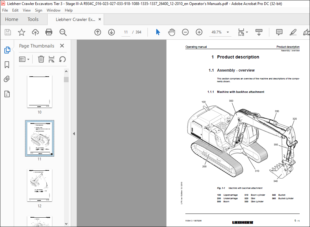
TABLE OF CONTENTS:
Liebherr Hydraulic excavator R 934 C Operating manual 26400 – PDF DOWNLOAD
Table of contents
1 Product description 1-1
1 1 Assembly – overview 1-1
1 1 1 Machine with backhoe attachment 1-1
1 1 2 Machine with industrial attachment 1-2
1 1 3 Uppercarriage 1-3
1 1 4 Undercarriage 1-4
1 2 Vibration emissions 1-4
1 3 Sound emission 1-5
1 4 EC Declaration of Conformity 1-6
1 5 Technical data 1-6
2 Safety instructions, Signs on the machine 2-1
2 1 Meaning of the symbols in this manual 2-1
2 2 Use in accordance with the regulations 2-2
2 3 Safety Instructions 2-2
2 4 Servicing the machine safely 2-14
2 5 Signs on the machine 2-20
2 5 1 Introduction 2-20
2 5 2 Arrangement of signage 2-21
2 5 3 Explanation of signage 2-22
2 5 4 Nameplates on the machine 2-27
3 Control and operation 3-1
3 1 Operating and control elements 3-1
3 1 1 Controls in the operator’s cab 3-1
3 1 2 The joysticks 3-3
3 1 3 Control unit 3-7
3 1 4 Monitoring display 3-12
3 1 5 Main screen 3-16
3 1 6 Information provided in the menus (Software versions V4 4 & V4 5) 3-22
3 1 7 Glancing through the available menus 3-36
3 1 8 Controls and instrumentation for optional equipments 3-37
3 1 9 Display for LIEBHERR particle filter (optional) 3-40
3 2 The access and the outfit of the cab 3-42
3 2 1 Entering or leaving the cab 3-43
3 2 2 The safety lever 3-45
3 2 3 Operator’s seat 3-46
3 2 4 Windscreen 3-50
3 2 5 Sunshade 3-51
3 2 6 Emergency exit – rear window 3-51
3 2 7 Interior lighting 3-52
3 2 8 Fire extinguisher* 3-52
3 2 9 Windscreen wiper 3-53
3 2 10 Lighting 3-55
3 2 11 The heater and air conditioner 3-57
3 2 12 Additional standstill heater (Option) 3-62
3 3 Setting the machine into operation 3-66
3 3 1 Before starting the machine 3-68
3 3 2 Turning on the electrical system 3-69
3 3 3 Starting the Diesel engine 3-70
3 3 4 Speed adjustment and operating modes 3-71
3 3 5 Notes after starting the engine 3-73
3 3 6 Warm-up phase for Diesel engine and hydraulic circuit 3-73
3 3 7 Switching the Diesel engine off 3-74
Table of contents Operating manual
R 934 C / 10070206
MJFCIFSS
3 3 8 Starting aids 3-75
3 3 9 Jump start procedure 3-77
3 3 10 Anti-theft device with code key (option) 3-77
3 3 11 Immobilizer with electronic ignition key (option) 3-78
3 4 Operating the excavator in safety modes 3-80
3 4 1 Board E52 for safety mode of Diesel engine & servo control 3-80
3 4 2 Safety operation of the main working pumps 3-83
3 5 Recovering, towing the machine 3-84
3 5 1 Towing the machine 3-84
3 6 Working with the machine 3-85
3 6 1 Low idle automatic 3-90
3 6 2 Automatic motorstop after low idle (in option) 3-91
3 6 3 Travel functions 3-91
3 6 4 Drive warning device (optional extra) 3-95
3 6 5 The uppercarriage swing movements 3-96
3 6 6 Working position 3-99
3 6 7 Working attachment control 3-99
3 6 8 Lowering the working attachment with the engine shut down 3-101
3 6 9 Control of a rotating device 3-102
3 6 10 Control of the swivel rotator (option) 3-103
3 6 11 Lifting magnet control system (optional equipment) 3-105
3 6 12 Control of special equipments via the additional pedals 3-106
3 6 13 Commutation of the controls for an additional user AHS (special equipment) 3-109
3 6 14 Special control system of the joysticks (Option) 3-110
3 6 15 Special control system of the joysticks 3-111
3 6 16 Special control (option) 3-114
3 6 17 Mechanical stanchion cylinder shut-down (option) 3-115
3 6 18 Use of the excavator for lifting loads overhead 3-117
3 6 19 Overload warning device (Option) 3-118
3 6 20 Hydraulically adjustable cab (option) 3-120
3 7 Attaching and dismounting equipment parts 3-123
3 7 1 Removal and installation of a bucket 3-124
3 7 2 Attaching and dismounting the bucket with improved sealing 3-126
3 7 3 Attaching and dismounting the grab on stick 3-128
3 7 4 Attaching and dismounting the grab on the industrial stanchion 3-131
3 7 5 Attaching and dismounting the stick to the boom 3-133
3 7 6 Mechanical quick-change adapter (optional extra) 3-135
3 7 7 Hydraulic quick-change adapter (optional extra) 3-139
3 7 8 LIKUFIX – hydraulic coupling system (optional extra) 3-146
3 8 General working methods 3-149
3 8 1 Minimum impact working methods for your machine 3-149
3 8 2 Preparatory activities 3-149
3 8 3 Using a backhoe bucket 3-150
3 8 4 Loading a transport vehicle 3-152
3 8 5 Skimming 3-152
3 8 6 Using a clamshell bucket (earthmoving attachment) 3-153
3 8 7 Using a multiple tine grapple (industrial attachment) 3-156
3 8 8 Using an hydraulic hammer 3-157
3 8 9 Working with a bottom dump bucket 3-158
3 9 Adjustment of undercarriage width (option) 3-160
3 9 1 Mechanic changing of undercarriage width 3-160
3 9 2 Hydraulic adjustment of undercarriage width 3-166
3 10 Transport 3-167
3 10 1 Loading the machine with a crane 3-171
3 10 2 To secure the machine: 3-173
4 Malfunctions 4-1
4 1 Error code charts 4-2
4 1 1 Machine Control system (BST) 4-2
4 1 2 Engine control system (PLD-CR) 4-3
4 1 3 Keypad 4-6
4 1 4 Display 4-6
4 1 5 Coding error 4-7
4 1 6 Other errors 4-7
4 1 7 Error due to warning symbols in SY field 4-7
4 2 Faults and remedies 4-9
4 2 1 Diesel engine and fuel system 4-9
4 2 2 Hydraulic system 4-10
4 2 3 Transmission 4-11
4 2 4 Electrical system 4-11
4 2 5 Work equipment 4-12
4 2 6 Heating/air-conditioning system 4-12
4 2 7 LIEBHERR particles filter system 4-14
4 3 Fuses and relays 4-15
4 3 1 Fuse box E50 4-15
4 3 2 A1010 Plate 4-16
5 Maintenance 5-1
5 1 Servicing the machine safely 5-1
5 2 Maintenance access doors 5-7
5 2 1 Overview of access doors 5-7
5 2 2 Door lock 5-8
5 3 Lubricants and operating fluids 5-9
5 3 1 General information on changing lubricants and operating fluids 5-9
5 3 2 Lubrication chart 5-10
5 3 3 Lubricant chart 5-12
5 3 4 Fuels, lubricants and process chemicals 5-13
5 4 Lubricants and fluids specification 5-13
5 4 1 Diesel fuel 5-13
5 4 2 Lubricating oil for the Diesel engine 5-14
5 4 3 Coolant for the diesel engine 5-16
5 4 4 Hydraulic liquids 5-23
5 4 5 Lubricating grease and other lubricants 5-27
5 5 Diesel engine 5-28
5 5 1 Checking the oil level in the diesel engine 5-28
5 5 2 Changing the diesel engine oil 5-29
5 5 3 Belt for the A/C compressor and alternator installation 5-30
5 5 4 Lubricating starter ring gear 5-31
5 5 5 Vibration damper 5-32
5 5 6 Checking mounting screws 5-32
5 5 7 Oil separator 5-33
5 5 8 Heater flange 5-34
5 5 9 Checking and adjustment of valve clearance 5-34
5 6 LIEBHERR particles filter (In option) 5-37
5 6 1 Drain the condensation water: 5-37
5 6 2 Water separator maintenance: 5-37
5 7 Cooling system 5-38
5 7 1 Checking and cleaning the cooling system 5-38
5 7 2 Checking the coolant level 5-39
5 7 3 Coolant antifreeze and anti-corrosion fluid 5-39
5 7 4 Changing the coolant 5-39
5 7 5 Reversible fan (optional extra) 5-42
5 8 Fuel system 5-43
5 8 1 Refuelling 5-43
5 8 2 Electrical refuelling pump (optional extra) 5-44
5 8 3 Draining the fuel tank 5-46
5 8 4 Emptying and cleaning the fuel tank 5-47
5 8 5 Draining the fuel prefilter 5-47
5 8 6 Changing fuel filter cartridges 5-48
5 8 7 Bleeding the fuel system 5-50
5 9 Dry air filter 5-53
5 9 1 Changing the main element 5-54
5 9 2 Changing the safety element 5-56
5 9 3 Monitoring the filtered air line 5-56
5 9 4 Spark catcher (option) 5-56
5 10 Hydraulic system 5-57
5 10 1 Depressurizing the hydraulic system 5-57
5 10 2 Checking the oil level, emptying and refilling the hydraulic tank 5-58
5 10 3 Return-line filter 5-62
5 10 4 Leak oil filter 5-63
5 10 5 Control oil filter 5-63
5 10 6 Replenishing oil filter in swing circuit 5-65
5 10 7 Control circuit 5-65
5 10 8 Bleeding the hydraulic pumps 5-66
5 10 9 Bleeding the hydraulic cylinders 5-67
5 10 10 Removing the intake hose to the pumps 5-69
5 10 11 Vent filter on the hydraulic tank 5-70
5 10 12 Bypass oil filter (option) 5-71
5 10 13 Bypass oil filter for hydraulic system (Special equipment) 5-72
5 10 14 Return oil filter for hydraulic hammer (option) 5-74
5 10 15 Servicing the hydraulic cylinder 5-75
5 10 16 Replacing hydraulic hoses 5-76
5 11 Oil changes on components 5-77
5 11 1 General information 5-77
5 11 2 Swing gear – Oil level check and oil change 5-78
5 11 3 Travelling gear – changing the oil 5-79
5 11 4 Splitterbox – Oil change 5-80
5 12 Travel gear 5-81
5 12 1 Checking the travel gear component mountings 5-81
5 12 2 Checking the track chains tension 5-82
5 12 3 Retensioning the track 5-84
5 12 4 Releasing the track chain tension 5-84
5 12 5 Cleaning the track components 5-85
5 13 Undercarriage with adjustable track gauge 5-86
5 13 1 Adjusting the track gauge of the undercarriage 5-88
5 13 2 Lubrication of the undercarriage 5-93
5 13 3 Checking the slide clearance on the track width adjustment 5-97
5 14 Electrical system 5-101
5 14 1 Notes on the electrical system 5-101
5 14 2 Main battery switch 5-101
5 14 3 Battery care 5-102
5 15 Heating/air-conditioning system 5-103
5 15 1 Recirculated and fresh air filters 5-103
5 15 2 Heating system 5-104
5 15 3 Air-conditioning system 5-105
5 15 4 Cab pressuring system (in option) 5-107
5 16 Greasing the machine 5-108
5 16 1 The centralized lubrication system 5-108
5 16 2 Semi automatic and full automatic systems 5-110
5 16 3 Operation of the semi automatic system 5-110
eration of the full automatic system 5-111
5 16 5 Emergency lubrication with defective lubrication system 5-113
5 16 6 To refill a grease container 5-114
5 16 7 Greasing the grab (optional extra) 5-115
5 16 8 Greasing the shovel (optional extra) 5-116
5 17 Quick-change systems 5-116
5 17 1 Greasing the mechanical quick-change adapter (optional extra) 5-116
5 17 2 Hydraulic quick-change adapter (optional extra) 5-117
5 17 3 LIKUFIX (optional extra) 5-118
5 18 Check mounting bolts for tightness 5-120
5 18 1 Mounting bolts of the counterweight 5-120
5 18 2 Mounting screws of the swing ring 5-120
5 18 3 Mounting screws of the hydraulic oil and fuel tank 5-121
5 18 4 Mounting screws of the swing gear and motor 5-121
5 19 Drive unit brakes and swing gear brakes 5-122
5 20 General maintenance points 5-122
5 20 1 Replacing working parts 5-122
5 20 2 Checking or replacing the teeth on the bucket 5-122
5 20 3 Welding work on the machine 5-124
5 21 Control and maintenance chart 5-125
VIDEO PREVIEW OF THE MANUAL:
PLEASE NOTE:
- This is the same manual used by the DEALERSHIPS to SERVICE your vehicle.
- The manual can be all yours – Once payment is complete, you will be taken to the download page from where you can download the manual. All in 2-5 minutes time!!
- Need any other service / repair / parts manual, please feel free to contact us at heydownloadss @gmail.com . We may surprise you with a nice offer
S.M


