

Kubota U17 U17-3 Excavator Workshop Manual – PDF DOWNLOAD
DESCRIPTION:
Kubota U17 U17-3 Excavator Workshop Manual – PDF DOWNLOAD
SAFETY PRECAUTIONS FOR SERVICING, DISASSEMBLY AND REASSEMBLY
Safety precautions for servicing
Most accidents during servicing arise from carelessness. Please remember that safety involves both the
welfare of the employees and improved work efficiency.
Safety precautions for disassembly and reassembly
Machines must be disassembled and assembled efficiently and safely.
It is very important to thoroughly understand the construction and function of the machine, to make all appropriate
preparations, and start operations according to the specified working procedures.
a) Safety Measures Before Starting Work
(1)Work clothes
1. Wear specified work cap and clothed.
(Under no circumstances may workers wear
undershirts only.)
Cuffs must be kept buttoned, and any tears
must be mended.)
2. Wear safety shoes.
3. Do not wear cotton gloves when working on
the internal section of engine, reduction
gears or hydraulic units for repair or others,
or when using a hammer. Wear leather
gloves, however, when hoisting wires.
(2)Inspecting equipment and tools
1. Prepare equipment (cranes, fork lifts, tool,
etc.) required for servicing and inspect for
any problems before starting work.
2. Hammer heads (metal parts) must be firmly
secured to their handles.
3. Check hosting tools (wire ropes, hoisting
chains, etc.) before use.
(3)Set workshop in order
1. Secure appropriate space needed for disassembly.
2. Secure a clean, safe place for arranging disassembled
parts.
3. Store volatile substances (gasoline, light oil,
thinner, oily articles, etc.) in appropriate
containers at selected locations to prevent
fire hazards
TABLE OF CONTENTS:
Kubota U17 U17-3 Excavator Workshop Manual – PDF DOWNLOAD
WSM U17_U17-3……………………………………………………………………….. 1
CONTENTS………………………………………………………………………… 3
I . GENERAL……………………………………………………………………… 5
(A) BODY AND ENGINE IDENTIFICATION MARKS………………………………………… 7
(B) SAFETY PRECAUTIONS FOR SERVICING, DISASSEMBLY AND REASSEMBLY…………………… 9
a) Safety Measures Before Starting Work……………………………………… 9
b) Safety Measures During Work……………………………………………… 9
c) Preparation for Disassembly……………………………………………… 10
d) Precautions for Disassembly and Reassembly………………………………… 10
(C) IMPORTANT SAFETY PROCESS AND CRITICAL FUNCTIONAL PROCESS………………………. 11
(D) IMPORTANT INSPECTION ITEMS AFTER REASSEMBLING………………………………… 13
a) Piping………………………………………………………………… 13
(E) MAINTENANCE INTERVALS……………………………………………………… 19
a) EU-version…………………………………………………………….. 19
b) PP (KTC, KCL)-version…………………………………………………… 23
c) KTA-version……………………………………………………………. 25
d) Hydraulic Oil Check for Machines with Hydraulic Breakers……………………. 26
e) Maintenance Items………………………………………………………. 27
f) Troubleshooting for Operators……………………………………………. 29
g) Periodic Replacement of Important Component Parts………………………….. 30
h) Recommended Oils……………………………………………………….. 31
i) Lifting Capacity……………………………………………………….. 32
(F) PRODUCT INFORMATION……………………………………………………….. 37
a) U17-3a, U17, U17-3 Development Concept……………………………………. 37
b) Why Minor Change?………………………………………………………. 37
c) Quick Chart……………………………………………………………. 38
d) Major Sales Feature…………………………………………………….. 39
e) Specifications Comparison……………………………………………….. 40
II . MACHINE BODY (Mechanism Section)………………………………………………. 41
(A) MACHINE SPECIFICATIONS…………………………………………………….. 43
a) Major Dimensions and Working Range (with Rubber Crawler)……………………. 43
b) Dimensions…………………………………………………………….. 45
c) Main Specifications…………………………………………………….. 47
d) U17-3a vs U17/U17-3…………………………………………………….. 48
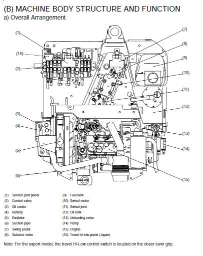
(B) MACHINE BODY STRUCTURE AND FUNCTION…………………………………………. 49
a) Overall Arrangement…………………………………………………….. 49
b) Under Carriage Components……………………………………………….. 55
II . MACHINE BODY (Service Section)………………………………………………… 65
(A) SPECIFICATIONS……………………………………………………………. 67
a) Machine Weight…………………………………………………………. 67
b) Main Specifications…………………………………………………….. 67
c) Lever Stroke and Operating Force…………………………………………. 68
d) Dimensions of Parts…………………………………………………….. 69
e) Quality Specifications………………………………………………….. 78
(B) FRONT ATTACHMENT………………………………………………………….. 89
a) Pin, Bush and Shim Installation………………………………………….. 89
b) Instruction to Press in the Bushing………………………………………. 93
c) Greasing Points………………………………………………………… 98
(C) UPPER STRUCTURE……………………………………………………………103
a) Swivel Bearing………………………………………………………….103
b) Travel Lever……………………………………………………………104
c) Accelerator Lever……………………………………………………….107
d) Dozer Lever…………………………………………………………….112
f) Swing Pedal…………………………………………………………….116
g) Service Port Pedal………………………………………………………118
h) Pilot Control Valve……………………………………………………..119
i) Limit Switch Installation………………………………………………..122
j) Seat and Seat Belt………………………………………………………123
k) Wrist Rest……………………………………………………………..124
l) Canopy…………………………………………………………………125
m) Weight…………………………………………………………………127
(D) UNDERCARRIGE………………………………………………………………129
a) Track Tension Device…………………………………………………….129
b) Track Roller……………………………………………………………132
III . ENGINE (Mechanism Section)……………………………………………………133
(A) ENGINE SPECIFICATIONS………………………………………………………135
(B) NEW EMISSIONS CONTROL ENGINES……………………………………………….139
a) Outline………………………………………………………………..139
b) Engine List for Minor Change……………………………………………..140
c) Engine Features…………………………………………………………141
III . ENGINE (Service Section)……………………………………………………..149
(A) ENGINE ACCESSORIES…………………………………………………………151
a) Engine Mount……………………………………………………………151
b) Air Cleaner…………………………………………………………….153
c) Radiator……………………………………………………………….156
d) Thermostat……………………………………………………………..164
e) Muffler………………………………………………………………..165
f) Pump Coupling…………………………………………………………..168
g) Fuel Tank………………………………………………………………169
h) Fuel Hoses……………………………………………………………..173
i) Engine Outlook………………………………………………………….174
Engine WSM : SM-E3B SERIES……………………………………………………..175
IV . HYDRAULIC SYSTEM (Mechanism Section)……………………………………………319
(A) HYDRAULIC SYSTEM…………………………………………………………..321
a) Main Pump………………………………………………………………321
b) Control Valve…………………………………………………………..328
c) Swivel Motor……………………………………………………………336
d) Travel Motor (Wheel Motor)……………………………………………….350
e) Pilot Valve (Remote Control Valve)………………………………………..360
f) Unload Valve……………………………………………………………369
g) Selector Valve………………………………………………………….370
h) Accessories of Hydraulic Components……………………………………….371
i) Service Port System……………………………………………………..377
j) TPSS (Two Pattern Selection System) : PP – version………………………….379
k) Hydraulic Components Layout: U17-3a, U17/U17-3……………………………..383
l) Hydraulic Circuit Diagram………………………………………………..384
IV . HYDRAULIC SYSTEM (Service Section)……………………………………………..391
(A) TROUBLESHOOTING……………………………………………………………393
a) Common Circuit………………………………………………………….393
b) Hydraulics……………………………………………………………..396
c) Pump…………………………………………………………………..399
d) Motor………………………………………………………………….400
e) Swivel Performance………………………………………………………401
f) Traveling Performance……………………………………………………403
(B) TESTING…………………………………………………………………..405
a) Testing Instruments & Special Tools……………………………………….405
b) Pump Flow………………………………………………………………407
c) Pressure Measurement…………………………………………………….408
d) Drain Measurement……………………………………………………….418
e) Measurement of Block Performance………………………………………….420
f) Operating Speed…………………………………………………………422
g) Straight Travel Performance………………………………………………424
h) Swivel System Diagnosis………………………………………………….425
i) Travel System Diagnosis………………………………………………….428
j) Cylinder natural fall amount……………………………………………..433
k) Control and Traveling lever operating force………………………………..433
l) Lever stroke……………………………………………………………433
(C) SPECIFICATIONS…………………………………………………………….435
a) Pump Specifications……………………………………………………..435
b) Relief Valve……………………………………………………………436
c) Swivel Performance………………………………………………………438
d) Traveling Performance……………………………………………………439
e) Cylinder……………………………………………………………….440
f) Service Port Flow Amount…………………………………………………442
g) Motor Oil Drain Amount Test Sample………………………………………..442
(D) DISASSEMBLING AND REASSEMBLING………………………………………………443
a) Pump…………………………………………………………………..443
b) Control Valve…………………………………………………………..458
c) Pilot Valve…………………………………………………………….501
d) Swivel Motor……………………………………………………………536
e) Rotary Joint……………………………………………………………550
f) Travel Motor……………………………………………………………562
g) Cylinder……………………………………………………………….581
h) Change Valve (Dozer, Track)………………………………………………590
i) Unload Valve……………………………………………………………592
j) Accumulator…………………………………………………………….596
k) Oil Tank……………………………………………………………….599
l) Third Line……………………………………………………………..600
m) TPSS Valve (PP-version Only)……………………………………………..602
n) Hydraulic Hose………………………………………………………….609
V . ELECTRICAL SYSTEM (Mechanism Section)……………………………………………623
(A) GENERAL…………………………………………………………………..625
a) New Functions of Electrical System………………………………………..625
(B) KUBOTA INTELLIGENT CONTROL SYSTEM (KICS)……………………………………..629
a) Features of Digital Meter………………………………………………..629
b) Operating Mode………………………………………………………….634
c) Servide Mode Menues……………………………………………………..637
d) Auto Idoling (AI) Control System………………………………………….657
e) Main Component’s Function………………………………………………..658
f) Failure Diagnosis……………………………………………………….664
g) Service Mode Flow Chart………………………………………………….672
h) Electrical Component Layout………………………………………………675
i) Electric Circuit Diagram, EU – version…………………………………….676
j) Electric Circuit Diagram, PP – version…………………………………….677
k) Electrical Wiring Diagram, EU – version……………………………………678
l) Electrical Wiring Diagram, PP – version……………………………………679
V . ELECTRICAL SYSTEM (Service Section)……………………………………………..681
(A) TROUBLESHOOTING……………………………………………………………683
a) General………………………………………………………………..683
b) Engine…………………………………………………………………684
c) Panel Relevant (Key Switch: ON)…………………………………………..685
d) Panel Relevant (Engine Starting)………………………………………….686
e) Others…………………………………………………………………687
(B) TROUBLE/ALARM DISPLAYS AND CHECKPOINTS……………………………………….689
a) Quick Diagnosis…………………………………………………………689
b) Kubota I.C.S. Navigation List of Messages………………………………….690
(C) INSPECTION………………………………………………………………..691
a) Coupler Check…………………………………………………………..691
b) Components Check………………………………………………………..692
c) Fuse Inspection…………………………………………………………695
d) Harness Check…………………………………………………………..696
e) Battery Check…………………………………………………………..696
f) Measuring Instruments and Special Tools……………………………………697
(D) WIRE HARNESS INSTALLATION…………………………………………………..699
a) Precautions in Clamping the Electrical Cabling……………………………..699
b) Harness Layout, Overview…………………………………………………701
c) Engine Room…………………………………………………………….702
d) Engine’s Top……………………………………………………………705
e) Cabling the Unload and Horn Switch………………………………………..706
f) Routing the Front Electrical Cables……………………………………….708
g) High-speed Switch, Horn………………………………………………….709
h) Electrical Cabling (Engine Room, Fuel Sensor)………………………………710
i) Electrical Cabling Route (Unload, Horn)……………………………………711
j) Electrical Cabling (Horn and Dual-speed Wire Harnesses in Right-hand Console)….712
(E) MAIN COMPONENTS MAINTENANCE…………………………………………………713
a) Checking the Fuses………………………………………………………713
b) Checking the Battery…………………………………………………….713
c) Checking the Horn……………………………………………………….714
d) Checking the Glow Relay………………………………………………….715
e) Glow Plug………………………………………………………………716
f) Unload Safety Switch…………………………………………………….717
g) Hi-Low Travel Switch…………………………………………………….719
h) Checking the Solenoid Valve………………………………………………720
i) Checking the Fuel Pump…………………………………………………..723
j) Checking the Fuel Sensor…………………………………………………725
k) Engine Stop Solenoid and Coil Commander……………………………………727
l) Checking the Water Temperature Gauge………………………………………728
m) Oil Switch……………………………………………………………..729
n) Relay………………………………………………………………….731
o) Installation of Canopy Light for KTA………………………………………732
Conversion Tables…………………………………………………………………737
IMAGES PREVIEW OF THE MANUAL:

VIDEO PREVIEW OF THE MANUAL:

PLEASE NOTE:
- This is the same manual used by the DEALERSHIPS to SERVICE your vehicle.
- The manual can be all yours – Once payment is complete, you will be taken to the download page from where you can download the manual. All in 2-5 minutes time!!
- Need any other service / repair / parts manual, please feel free to contact us at heydownloadss @gmail.com . We may surprise you with a nice offer
S.V


