

Kubota R420α R520α R420S R520S Wheel Loader Workshop Manual – PDF DOWNLOAD
DESCRIPTION:
Kubota R420α R520α R420S R520S Wheel Loader Workshop Manual – PDF DOWNLOAD
a) Safety measures before starting work :
b) Safety measures during work
Most accidents during servicing arise from carelessness. Please remember that safety involves both the welfare
of the employees and improved work efficiency.
Machines must be disassembled and assembled efficiently and safely.
It is very important to thoroughly understand the construction and function of the machine, to make all
appropriate preparations, and start operations according to the specified working procedures.
[1] Work clothes
1. Wear specified work cap and clothed. (Under no circumstances may workers wear undershirts only.)
Cuffs must be kept buttoned, and any tears must be mended.)
2. Wear safety shoes.
3. Do not wear cotton gloves when working on the internal section of engine, reduction gears or hydraulic units for
repair or others, or when using a hammer. Wear leather gloves, however, when hoisting wires.
[2] Inspecting equipment and tools
1. Prepare equipment (cranes, fork lifts, tool, etc.) requires for servicing and inspect for any problems before
starting work.
2. Hammer heads (metal parts) must be firmly secured to their handles.
3. Check hosting tools (wire ropes, hosting chains, etc.) before use.
[3] Keep workshop in order
1. Secure appropriate space needed for disassembly to the job.
2. Secure a clean, safe place for arranging disassembled parts.
3. Store volatile substances (gasoline, light oil, thinner, oily articles, etc.) in appropriate containers at selected
locations to prevent fire hazards.
TABLE OF CONTENTS:
Kubota R420α R520α R420S R520S Wheel Loader Workshop Manual – PDF DOWNLOAD
COVER…………………………………………………………………………………. 1
CONTENTS………………………………………………………………………………. 3
I. GENERAL…………………………………………………………………………….. 5
(A) BODY AND ENGINE IDENTIFICATIONS MARKS……………………………………………… 6
(B) SAFETY PRECAUTIONS FOR SERVICING, DISASSEMBLY AND REASSEMBLY…………………………. 8
a) Safety measures before starting work……………………………………………. 8
b) Safety measures during work……………………………………………………. 8
c) Preparation for disassembly……………………………………………………. 10
d) Precautions for disassembly and reassembly………………………………………. 10
(C) IMPORTANT SAFETY PROCESS AND CRITICAL FUNCTIONAL PROCESS…………………………….. 12
(D) IMPORTANT INSPECTION ITEMS AFTER REASSEMBLING………………………………………. 14
a) Operate the machine and check for unusual noise and vibrations…………………….. 14
b) Make sure the safety decals and wireharness clamps are in their specified positions….. 14
c) With the machine front in a specified posture, check the amount of hydraulic oil…….. 14
(E) SERVICE FUNDAMENTALS…………………………………………………………….. 16
a) Service intervals…………………………………………………………….. 16
b) Lubricants…………………………………………………………………… 18
c) Notices for service items……………………………………………………… 18
d) Tightening torque…………………………………………………………….. 20
II. MACHINE BODY-Mechanism………………………………………………………………. 29
(A) MACHINE SPECIFICATIONS…………………………………………………………… 30
a) Specification Table (1)……………………………………………………….. 30
b) Specification Table(2), Backhoe-version…………………………………………. 32
c) Lifting Capacity……………………………………………………………… 32
(B) DEVELOPMENT CONCEPT OF MODEL CHANGE……………………………………………….. 34
a) Two Main Concepts…………………………………………………………….. 34
b) Product Feature………………………………………………………………. 34
c) Looks and Design Renewal………………………………………………………. 38
d) Attachments and Regulation…………………………………………………….. 38
e) Quality Improvement, Main Points……………………………………………….. 40
f) Quality Improvement: Improved Startup Acceleration……………………………….. 42
g) Quality Improvement: Bucket Dump Angle………………………………………….. 42
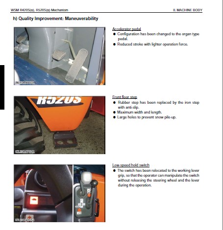
h) Quality Improvement: Maneuverability……………………………………………. 44
i) Quality Improvement: Durability & Reliability……………………………………. 44
j) Quality Improvement: Operator Comfort, Travelling Noise Reduction………………….. 46
k) Quality Improvement: Operator Comfort, Miscellaneous……………………………… 46
l) Prevention Of Oil Leakage From Axle Shaft……………………………………….. 48
(C) QUALITY SPECIFICATIONS: R420S, R520S………………………………………………. 48
(D) FRONT ATTACHMENT………………………………………………………………… 52
(E) FRAME ARTICULATION AND CENTER PIN…………………………………………………. 54
II. MACHINE BODY & FRONT ATTACHMENT-Service……………………………………………….. 56
(A) MACHINE SPECIFICATIONS…………………………………………………………… 58
a) Specification Table: PP-version (KTC, KCL, KTA)………………………………….. 58
b) Main Specification: EU-version…………………………………………………. 60
c) Dimensional Specifications…………………………………………………….. 62
d) Specification Table: Backhoe…………………………………………………… 64
e) Parts Weight Table……………………………………………………………. 64
f) EU-version machine weight……………………………………………………… 66
g) Front pin, Front bush…………………………………………………………. 66
h) Front Parts dimensinon………………………………………………………… 68
i) Center Pins and Bushing……………………………………………………….. 72
j) Bucket dimension……………………………………………………………… 72
(B) INSTALLING FRAME-RELATED PARTS (FRONT)…………………………………………….. 74
(C) CENTER PIN (IMPORTANT FUNCTIONAL COMPONENT)………………………………………… 76
(D) REAR FRAME, CENTER PIN…………………………………………………………… 80
(E) ASSEMBLY DRAWING OF THE CONTROL LEVERS…………………………………………….. 86
(F) INSTALLING THE CONTROL LEVERS…………………………………………………….. 88
(G) ASSEMBLY DRAWING OF ACCELERATOR AND BRAKE………………………………………….. 92
(H) INSTALLING THE BRAKE AND INCHING-RELATED PARTS……………………………………… 96
(I) INSTALLING THE ACCELERATOR-RELATED PARTS……………………………………………100
(J) INSTALLING THE SEAT………………………………………………………………102
(K) FENDER………………………………………………………………………….104
(L) INSTALLING THE CANOPY…………………………………………………………….106
(M) CAB…………………………………………………………………………….110
(N) HEATER HOSE……………………………………………………………………..112
III. ENGINE-Mechanism……………………………………………………………………118
(A) ENGINE SPECIFICATIONS…………………………………………………………….120
(B) ENGINE PERFORMANCE CURVE………………………………………………………….122
(C) NEW EMISSIONS CONTROL ENGINES……………………………………………………..124
a) Outline………………………………………………………………………124
b) Engine List for Minor Change……………………………………………………126
c) Major Engine Specifications for Tier 4 / Interim Tier 4 Engine……………………..126
d) Performance Curve……………………………………………………………..128
(D) BOOST COMPENSATOR AND GOVERNOR…………………………………………………….132
III. ENGINE-Service……………………………………………………………………..136
(A) SPECIFICATIONS…………………………………………………………………..138
(B) ENGINE ASSY DISMOUNTING…………………………………………………………..140
(C) ENGINE ACCESSORIES……………………………………………………………….146
a) Engine Rubber Mount……………………………………………………………146
b) Radiator, Oil Cooler…………………………………………………………..148
c) Air Cleaner…………………………………………………………………..150
d) Muffler………………………………………………………………………152
e) Muffler Installation…………………………………………………………..154
f) Fuel Hose Route (S)……………………………………………………………154
g) Engine Oil Drain Hose………………………………………………………….156
h) Accel Pedal Control Linkage…………………………………………………….156
i) Hand Accel Pedal Control Linkage………………………………………………..158
j) New Engine Structure…………………………………………………………..158
(D). TURBO-CHARGER…………………………………………………………………..160
a) Specifications………………………………………………………………..160
b) Structure…………………………………………………………………….162
Engine WSM: 03-M-E3B, 03-M-DI-E3B, 03-M-E3BG……………………………………………165
TO THE READER……………………………………………………………………167
DIMENSIONS………………………………………………………………………184
GENERAL…………………………………………………………………………193
MECHANISM……………………………………………………………………….241
SERVICING……………………………………………………………………….249
IV. HYDRAULIC SYSTEM-Mechanism……………………………………………………………355
(A) CIRCUIT DIAGRAM & COMPONENTS………………………………………………………356
a) Hydraulic Circuit Diagram………………………………………………………356
b) Components Layout……………………………………………………………..358
(B) LST PUMP………………………………………………………………………..360
a) Function of LST Pump (A4v Pump)…………………………………………………360
b) Servo Cylinder (DA Regulator)…………………………………………………..362
c) High-pressure Relief Valve……………………………………………………..364
d) Low Pressure Relief Valve (Charge Relief Valve)…………………………………..366
e) Automatic Shift Function……………………………………………………….366
f) Torque Control Function………………………………………………………..366
g) Inclined Rotation Resetting Force and Advance Angle……………………………….368
h) LST Pump Orifice………………………………………………………………368
i) DA Valve (Speed Relay Valve)……………………………………………………370
j) Function of DA Valve…………………………………………………………..370
k) Bypassing the Looped Line………………………………………………………374
l) Improvement of Temperature Characteristics of LST System…………………………..374
(C) LST motor……………………………………………………………………….376
a) Series Comparison……………………………………………………………..376
b) LST Motor Structure……………………………………………………………378
c) LST Motor Diagram……………………………………………………………..378
d) LST Motor, Oil Flow……………………………………………………………380
e) LST Motor Mechanism……………………………………………………………382
f) LST Motor Servo-regulator………………………………………………………382
g) LST Motor Servo-regulator………………………………………………………384
h) Theory……………………………………………………………………….388
i) LST System Diagram…………………………………………………………….388
(D) STEERING SYSTEM………………………………………………………………….390
a) Steering Unit…………………………………………………………………390
IV. HYDRAULIC SYSTEM-Service……………………………………………………………..392
(A) TROUBLESHOOTING………………………………………………………………….394
a) Hydraulic system does not work………………………………………………….394
b) Weak lifting, any circuit………………………………………………………394
c) Slow lifting, any circuit………………………………………………………396
d) Cylinder Fall…………………………………………………………………396
e) Does not travel in both the F and R directions……………………………………396
f) Insufficient traction force in both the F and R directions…………………………398
g) Slow traveling speed in both the F and R directions……………………………….398
h) Too high starting engine rpm in both the F and R directions………………………..400
i) Too low starting engine rpm in both the F and R directions…………………………400
j) Difference in starting engine rpm between the F and R directions……………………400
k) Excessive LST brake shock………………………………………………………400
l) Insufficient acceleration………………………………………………………402
m) Insufficient traction force or traveling rpm in both the F and R directions………….402
n) Steering system……………………………………………………………….402
(B) SPECIFICATIONS…………………………………………………………………..404
a) LST System……………………………………………………………………404
b) Steering system……………………………………………………………….412
c) Front Loader………………………………………………………………….412
(C) TESTING…………………………………………………………………………418
a) Pressure Measurement…………………………………………………………..418
b) Flow Rate Measurement………………………………………………………….428
(D) SERVICING……………………………………………………………………….434
a) Dismounting and mounting LST pump & motor………………………………………..434
b) Repair instructions, LST pump…………………………………………………..440
c) Repair instructions, LST motor………………………………………………….480
d) Control valve servicing………………………………………………………..504
e) Steering unit…………………………………………………………………516
f) Cylinder servicing…………………………………………………………….552
V. BRAKE SYSTEM AND POWER TRAIN-Mechanism………………………………………………….574
(A) OUTLINE…………………………………………………………………………576
(B) PARKING BRAKE……………………………………………………………………578
(C) SERVICE BRAKE: AXLE BRAKE (EU, KCL, KTA-VERSION)…………………………………….580
(D) NEGATIVE BRAKE RELEASING METHOD……………………………………………………582
(E) POWER TRAIN COMPONENTS……………………………………………………………584
a) Front differential axle shaft assy………………………………………………584
b) Front differential axle shaft assy (Limited slip differential)……………………..586
c) Front axle……………………………………………………………………586
d) Rear differential axle shaft assy (without axle brake)…………………………….588
e) Rear differential axle shaft assy (with axle brake)……………………………….588
V. BRAKE SYSTEM AND POWER TRAIN-Service……………………………………………………590
(A) BRAKE SYSTEM…………………………………………………………………….592
a) Negative Brake………………………………………………………………..592
b) Parking Valve…………………………………………………………………594
(B) POWER TRAIN……………………………………………………………………..596
a) Front Axle……………………………………………………………………596
b) Rear Axle…………………………………………………………………….600
c) Differential Gear (LSD)………………………………………………………..606
d) Reduction Gear Case Assembly……………………………………………………612
e) Differential Ass’y (STD) Assembly……………………………………………….614
f) Rear Axle Assembly…………………………………………………………….614
g) Rear Differential Axle…………………………………………………………616
h) Front Differential Axle Assembly………………………………………………..616
i) Planetary Gear Assembly………………………………………………………..618
VI. ELECTRICAL SYSTEM-Mechanism…………………………………………………………..618
(A) ELECTRICAL WIRING: R420S/α, R520S/α………………………………………………..620
(B) ELECTRICAL CIRCUIT DIAGRAM………………………………………………………..622
VI. ELECTRICAL SYSTEM-Service…………………………………………………………….624
(A) TESTING…………………………………………………………………………626
(B) TROUBLESHOOTING………………………………………………………………….628
a) Battery discharges quickly……………………………………………………..628
b) Starter does not drive engine properly…………………………………………..628
c) Forward and reverse run not selectable…………………………………………..630
d) Low-speed hold not effective……………………………………………………630
e) Auto lever not effective……………………………………………………….632
(C) SPECIFICATIONS…………………………………………………………………..632
a) Service as required……………………………………………………………632
(D) WIRE HARNESS INSTALLATION…………………………………………………………642
a) Precautions…………………………………………………………………..642
b) Wire harness routes……………………………………………………………644
(E) SPECIFICATIONS FOR ELECTRIC COMPONENTS AND SERVICE…………………………………..652
a) Stop switch…………………………………………………………………..652
b) Starter switch………………………………………………………………..652
c) Glow lamp timer……………………………………………………………….654
d) Indicator-1…………………………………………………………………..654
e) Indicator-2…………………………………………………………………..654
f) Fuel gauge……………………………………………………………………656
g) Tachometer……………………………………………………………………656
h) Water temperature meter………………………………………………………..658
i) Hazard switch…………………………………………………………………658
j) Parking switch………………………………………………………………..658
k) Winker switch…………………………………………………………………660
l) Light switch………………………………………………………………….660
m) F-R switch……………………………………………………………………660
n) Horn switch…………………………………………………………………..662
o) Relay (starter)……………………………………………………………….662
p) Relay (F-R)…………………………………………………………………..662
q) Alternator……………………………………………………………………664
r) Sensor (auto leveler)………………………………………………………….664
s) Unit (inverter)……………………………………………………………….664
t) Control valve…………………………………………………………………664
u) Horn…………………………………………………………………………666
v) Relay (light)…………………………………………………………………666
w) Flasher unit………………………………………………………………….666
x) Relay (flasher R)……………………………………………………………..666
y) Relay (winker L)………………………………………………………………668
z) Auto leveler relay (control valve)………………………………………………668
aa) Parking solenoid……………………………………………………………..668
ab) Starter……………………………………………………………………..668
ac) Battery……………………………………………………………………..670
ad) Earth (battery)………………………………………………………………670
ae. Oil switch…………………………………………………………………..670
af) Earth-1……………………………………………………………………..670
ag) Earth-2……………………………………………………………………..670
ah) Fusible link (80A)……………………………………………………………672
ai) Fusible link (60A)……………………………………………………………672
aj) Fuse box…………………………………………………………………….672
ak) Rear combination lamp R……………………………………………………….672
al) Rear combination lamp L……………………………………………………….674
am) Front combination lamp………………………………………………………..674
an) Head lamp……………………………………………………………………674
ao) Oil temperature sensor………………………………………………………..674
ap) Water temperature sensor………………………………………………………676
aq) Low-speed hold solenoid……………………………………………………….676
ar) Fuel pump……………………………………………………………………676
as) F-R valve solenoid……………………………………………………………676
at) Low-speed hold switch…………………………………………………………678
au) Fuel sensor………………………………………………………………….678
av) Pressure switch………………………………………………………………680
aw) Engine stop solenoid………………………………………………………….680
ax) Back buzzer………………………………………………………………….680
ay) Back lamp……………………………………………………………………682
az) Relay (cab)………………………………………………………………….682
ba) Glow plug (cab)………………………………………………………………682
bb) Relay (glow)…………………………………………………………………682
bc) Cabin power supply……………………………………………………………684
bd) Relay (pressure switch)……………………………………………………….684
be) Coupler-1 (8-pole)……………………………………………………………684
bf) Coupler-2 (12-pole)…………………………………………………………..684
bg) Coupler-3 (10-pole)…………………………………………………………..686
bh) Coupler-4 (2-pole)……………………………………………………………686
bi) Coupler-5 (1-pole)……………………………………………………………686
bj) Fender installation…………………………………………………………..686
bk) Main parts installation……………………………………………………….688
VII. BACKHOE-Mechanism…………………………………………………………………..690
(A) OIL FLOW CHART OF BACKHOE…………………………………………………………692
(B) HYDRAULIC CIRCUIT DIAGRAM…………………………………………………………694
VII. BACKHOE-Service…………………………………………………………………….696
(A) SPECIFICATIONS…………………………………………………………………..698
a) General Dimension……………………………………………………………..698
b) Operating Performance………………………………………………………….700
c) Lifting Capacity (Backhoe)……………………………………………………..702
d) Hydraulic System Data………………………………………………………….702
e) Bucket, Boom, Arm Data…………………………………………………………710
f) Pin and Bushing Dimensions……………………………………………………..712
(B) TROUBLESHOOTING………………………………………………………………….714
a) Hydraulic Circuit……………………………………………………………..714
b) Mechanical Structure…………………………………………………………..716
(C) OPERATION AND MAINTENANCE…………………………………………………………716
a) Main Components……………………………………………………………….716
b) Operator’s Seat……………………………………………………………….718
c) Grease Fittings……………………………………………………………….718
(D) TESTING & ADJUSTMENT……………………………………………………………..720
a) Operating Speed……………………………………………………………….720
b) Hydraulic Cylinders Free Fall…………………………………………………..722
c) Main Relief Pressure…………………………………………………………..724
d) Overload Relief Pressure……………………………………………………….724
e) Control Lever Play and Stroke…………………………………………………..726
f) Control Lever Operating Force…………………………………………………..726
g) Bucket Sway Distance…………………………………………………………..726
(E) REMOVING & REASSEMBLING…………………………………………………………..728
a) Bucket, Arm & Boom…………………………………………………………….728
b) Swing Bracket…………………………………………………………………730
c) Slide Bracket…………………………………………………………………734
d) Swing Cylinder………………………………………………………………..736
e) Slide Lock Cylinder……………………………………………………………738
f) Piping Block………………………………………………………………….740
g) Control Valve…………………………………………………………………742
h) Pilot Operate Check Valve………………………………………………………744
i) Outrigger Cylinder…………………………………………………………….744
VIII. SUPPLEMENT………………………………………………………………………..744
(A) FUNDAMENTALS OF WHEEL LOADER………………………………………………………746
a) Glossary……………………………………………………………………..746
b) Relevant Performance Data………………………………………………………762
(B) INTRODUCTION OF LST SYSTEM………………………………………………………..766
(C) INTRODUCTION OF STEERING SYSTEM……………………………………………………782
a) Steering Performance…………………………………………………………..782
b) Basic Circuit of Steering System………………………………………………..784
c) Steering Valve (Orbitrol)………………………………………………………786
d) Features of Dynamic Signal Type…………………………………………………788
(D) WINKER PRIORITY CIRCUIT (KTC, KCL, KTA)…………………………………………….790
a) Winker SW, R………………………………………………………………….792
b) Winker SW, L………………………………………………………………….792
c) Hazard SW, ON…………………………………………………………………792
d) Winker SW, R and Hazard SW, ON………………………………………………….792
(E) HAZARD PRIORITY CIRCUIT (EU)………………………………………………………794
a) Winker SW, R………………………………………………………………….796
b) Winker SW, L………………………………………………………………….796
c) Hazard SW, ON…………………………………………………………………796
d) Hazard SW, ON and Winker SW, R ON……………………………………………….796
(F) ELECTRICAL CIRCUIT FUNCTION……………………………………………………….798
a) Glow Circuit………………………………………………………………….798
b) Starter Circuit……………………………………………………………….800
c) Engine Starts, Parking SW OFF, F/R Shuttle Lever to F……………………………..800
d) F/R Shuttle Lever to Reverse……………………………………………………802
e) Engine Oil Pressure SW Warning Circuit…………………………………………..802
f) Auto Leveller Circuit………………………………………………………….802
g) R420S·R420α, R520S·R520α Electrical circuit (Comparison)…………………………..804
(G) FYI (FOR YOUR INFORMATION)………………………………………………………..806
a) Electrical Wiring: R420S, R420Sα, R520S, R520Sα…………………………………..806
b) Electrical Circuit Diagram: R420S, R520S (PP- version)…………………………….808
c) Electrical Circuit Diagram: R420α, R520α (EU – version)……………………………809
d) R420S, R520S (PP – version)…………………………………………………….810
e) R420S, R420α, R520S, R520α (EU – version)………………………………………..811
f) R420S, R420α, R520S, R520α (EU – version)………………………………………..812
g) Hydraulic Circuit Diagram: R420S, R520S: North America & Oceania……………………813
h) Hydraulic Circuit Diagram: R420α, R520α, EU-version……………………………….814
i) Components Layout……………………………………………………………..815
j) Backhoe Circuit Diagram: R420S, R520S, R420α, R520α……………………………….816
Conversion Tables……………………………………………………………………….816
IMAGES PREVIEW OF THE MANUAL:

VIDEO PREVIEW OF THE MANUAL:

PLEASE NOTE:
- This is not a physical manual but a digital manual – meaning no physical copy will be couriered to you. The manual can be yours in the next 2 mins as once you make the payment, you will be directed to the download page IMMEDIATELY.
- This is the same manual used by the dealers inorder to diagnose your vehicle of its faults.
- Require some other service manual or have any queries: please WRITE to us at [email protected]
S.V


