

Komatsu PC40MR-3 Hydraulic Excavator Shop Manual WEN00005-00 – PDF DOWNLOAD
IMAGES PREVIEW OF THE MANUAL:
DESCRIPTION:
Komatsu PC40MR-3 Hydraulic Excavator Shop Manual WEN00005-00 – PDF DOWNLOAD
SERIAL NUMBERS 15001 and up
Foreword and general information
Safety notice
Important safety notice
Proper service and repair are extremely important for safe machine operation. The service and repair techniques recommended by Komatsu and described in this manual are both effective and safe. Some of these techniques require the use of tools specially designed by Komatsu for the specific purpose. To prevent injury to workers, the symbol k is used to mark safety precautions in this manual. The cautions accompanying these symbols should always be followed carefully. If any dangerous situation arises or may possibly arise, first consider safety, and take the necessary actions to deal with the situation
- 1. General precautions k Mistakes in operation are extremely dangerous. Read the Operation and
Maintenance Manual carefully before operating the machine. In addition, read this manual and understand its contents before starting the work.
1) Before carrying out any greasing or repairs, read all the safety labels stuck to the machine. For the locations of the
safety labels and detailed explanation of precautions, see the Operation and Maintenance Manual.
2) Decide a place in the repair workshop to keep tools and removed parts. Always keep the tools and parts in their correct places. Always keep the work area clean and make sure that there is no dirt, water, or oil on the floor. Smoke only in the areas provided for smoking. Never smoke while working.
3) When carrying out any operation, always wear safety shoes and helmet. Do not wear loose work clothes, or clothes with buttons missing. q Always wear safety glasses when hitting parts with a hammer. Always wear safety glasses when grinding parts with a grinder, etc.
4) When carrying out any operation with 2 or more workers, always agree on the operating procedure before starting. Always inform your fellow workers before starting any step of the operation. Before starting work, hang UNDER REPAIR warning signs in the operator’s compartment.
5) Only qualified workers must carry out work and operation which require license or qualification.
6) Keep all tools in good condition, learn the correct way to use them, and use the proper ones of them. Before starting work, thoroughly check the tools, machine, forklift, service car, etc. - 7) If welding repairs are needed, always have a trained and experienced welder carry out the work. When carrying out welding work, always wear welding gloves, apron, shielding goggles, cap and other clothes suited for welding work. 8)Before starting work, warm up your body thoroughly to start work under good condition.
- 9)Avoid continuing work for long hours and take rests at proper intervals to keep your body in good condition. Take rests in specified safe places
TABLE OF CONTENTS:
Komatsu PC40MR-3 Hydraulic Excavator Shop Manual WEN00005-00 – PDF DOWNLOAD
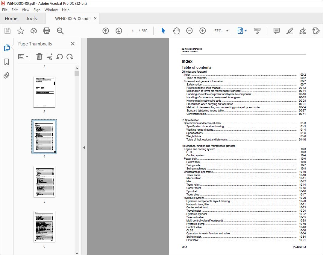
Table of contents 1
00 Index and foreword
Index 00-2
Table of contents 00-2
Foreword and general information 00-7
Safety notice 00-7
How to read the shop manual 00-12
Explanation of terms for maintenance standard 00-14
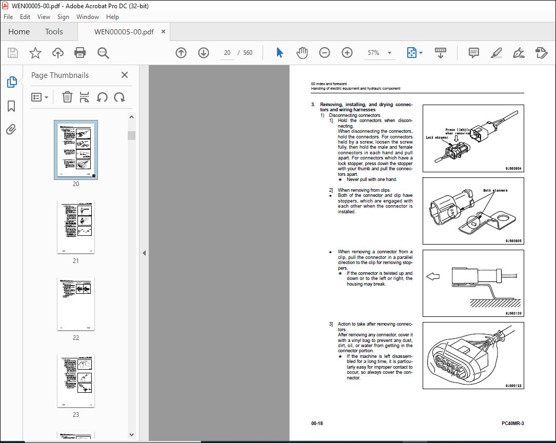
Handling of electric equipment and hydraulic component 00-16
Handling of connectors newly used for engines 00-25
How to read electric wire code 00-28
Precautions when carrying out operation 00-31
Method of disassembling and connecting push-pull type coupler 00-34
Standard tightening torque table 00-37
Conversion table 00-41
01 Specification
Specification and technical data 01-3
Specification dimension drawing 01-3
Working range drawing 01-4
Specifications 01-5
Weight table 01-8
Table of fuel, coolant and lubricants 01-10
10 Structure, function and maintenance standard
Engine and cooling system 10-3
PTO 10-3
Cooling system 10-4
Power train 10-6
Power train 10-6
Swing circle 10-7
Swing machinery 10-8
Undercarriage and frame 10-10
Track frame 10-10
Idler cushion 10-11
Idler 10-12
Track roller 10-14
Carrier roller 10-15
Sprocket 10-16
Track shoe 10-17
Hydraulic system 10-20
Hydraulic components layout drawing 10-20
Hydraulic tank, filter 10-21
Center swivel joint 10-23
Travel motor 10-24
Hydraulic cylinder 10-32
Solenoid valve 10-35
Multi-control valve (If equipped) 10-38
Hydraulic pump 10-40
Control valve 10-48
CLSS 10-60
Operation for each function and valve 10-64
Swing motor 10-84
PPC valve 10-91
Work equipment 10-104
Work equipment 10-104
Dimensions of each part of work equipment 10-108
Cab and its attachments 10-111
Floor 10-111
Electrical system 10-112
Engine control system 10-112
Electric control system 10-114
KOMTRAX system 10-119
Component parts of system 10-122
Monitor system 10-123
Sensors 10-126
20 Standard value table
Standard service value table 20-3
Standard service value table for engine related parts 20-3
Standard service value table for chassis related parts 20-4
30 Testing and adjusting
Related information on testing and adjusting 30-3
Tools for testing, adjusting, and troubleshooting 30-3
Engine and cooling system 30-6
Testing engine speed 30-6
Testing exhaust gas color 30-7
Testing and adjusting valve clearance 30-8
Testing compression pressure 30-10
Testing engine oil pressure 30-11
Testing and adjusting fuel injection timing 30-12
Testing and adjusting alternator belt tension 30-16
Testing and adjusting air conditioner compressor belt tension 30-17
Adjusting fuel control lever 30-18
Power train 30-19
Testing clearance in swing circle bearings 30-19
Undercarriage and frame 30-20
Testing and adjusting track shoe tension 30-20
Hydraulic system 30-21
Testing and adjusting oil pressures in work equipment, travel, boom swing, swing, and blade circuits
30-21
Testing and adjusting LS differential pressure 30-26
Adjusting PC valve 30-29
Testing and adjusting control pump circuit oil pressure 30-30
Testing solenoid valve output pressure 30-32
Testing PPC valve output pressure 30-33
Adjusting PPC valve 30-35
Testing swing holding brake release pressure 30-36
Testing and adjusting travel deviation 30-37
Testing oil leakage from work equipment cylinder 30-39
Bleeding air from each part 30-41
Releasing residual pressure from hydraulic circuit 30-43
Releasing residual pressure from hydraulic tank 30-44
Pressurizing hydraulic tank 30-44
Cab and its attachments 30-45
How to open and close (tilt) floor 30-45
Electrical system 30-50
How to start operation of KOMTRAX terminal 30-50
Lamp display of KOMTRAX terminal 30-54
Removal and installation of KOMTRAX terminal 30-57
Preparation work for troubleshooting of electrical system 30-58
Inspection procedures for diode 30-59
40 Troubleshooting
General information on troubleshooting 40-4
Points to remember when performing troubleshooting 40-4
How to proceed in troubleshooting 40-6
Checks before troubleshooting 40-8
Classification and procedures of troubleshooting 40-9
Information contained in troubleshooting table 40-10
Connection table of connector by No of pins 40-14
T- branch box and T- branch adapter table 40-51
User code and failure code list 40-55
Fuse locations 40-56
Troubleshooting by failure code 40-58
Failure code [DBHRKR] Communication error between monitor panel and attachment switch controller
40-58
Failure code [DBH1KK] Unswitched power supply error 40-60
Failure code [DBH2KK] Solenoid power supply error 40-62
Failure code [DBH5KP] 5V sensor power supply output 0 error 40-64
Failure code [DBH6KP] 5V sensor power supply output 1 error 40-65
Failure code [DK10KA] Fuel control dial potentiometer error (Disconnection or ground fault) 40-66
Failure code [DK10KB] Fuel control dial potentiometer error (Hot short circuit) 40-68
Failure code [DK58KA] Governor stroke sensor error (Disconnection or ground fault) 40-70
Failure code [DK58KB] Governor stroke sensor error (Hot short circuit) 40-72
Failure code [D1E0KZ] Motor power supply relay error (Disconnection or hot short circuit) 40-74
Failure code [D1E0KB] Motor power supply relay error (Ground fault) 40-76
Failure code [D1E1KZ] Motor drive relay (+) error (Disconnection or hot short circuit) 40-78
Failure code [D1E1KB] Motor drive relay (+) error (Ground fault) 40-80
Failure code [D1E2KZ] Motor drive relay (-) error (Disconnection or hot short circuit) 40-82
Failure code [D1E2KB] Motor drive relay (-) error (Ground fault) 40-84
Failure code [DY10MA] Fuel control motor operation error 40-86
Failure code [D1E0KA] Fuel control motor power supply relay contact sticking (NC side) 40-88
Failure code [D1E0KY] Fuel control motor power supply relay contact sticking (NO side) 40-90
Troubleshooting of electrical system (E-mode) 40-93
Before carrying out troubleshooting of electrical system 40-93
E-1 Engine does not start 40-94
E-2 Engine does not stop 40-102
E-3 When starting switch is turned ON, any item does not operate 40-104
E-4 When starting switch is turned ON, some items do not operate 40-106
E-5 Alarm buzzer is abnormal 40-107
E-6 Engine oil pressure caution is turned ON 40-109
E-7 Charge level caution is turned ON 40-110
E-8 Preheating system does not operate or preheater does not become hot 40-112
E-9 Coolant temperature gauge is abnormal 40-114
E-10 Fuel level gauge is abnormal 40-118
E-11 Service meter does not operate while engine is running 40-122
E-12 2nd travel speed is not selected 40-125
E-13 Working lamp does not light up 40-128
E-14 When work equipment lock (PPC basic pressure lock) lever is set in LOCK, work equipment still
moves 40-130
E-15 Windshield wiper does not operate 40-132
E-16 Windshield washer does not operate 40-134
E-17 Defective air conditioner 40-136
E-18 KOMTRAX system does not operate normally 40-144
Troubleshooting of hydraulic and mechanical system (H-mode) 40-147
Information contained in troubleshooting table 40-147
H-1 Speed or power of whole work equipment, travel, swing, and blade is low 40-148
H-2 Engine speed lowers extremely or engine stalls 40-152
H-3 Whole work equipment, travel system, swing system, and blade do not work 40-153
H-4 Abnormal sound comes out from around hydraulic pump 40-157
H-5 Fine control performance or response is low 40-157
H-6 Speed or power of boom is low 40-158
H-7 Speed or power of arm is low 40-159
H-8 Speed or power of bucket is low 40-160
H-9 Speed or power of boom swing is low 40-161
H-10 Work equipment does not move singly 40-161
H-11 Work equipment hydraulic drift is large 40-162
H-12 Time lag of work equipment is large 40-164
H-13 In compound operation of work equipment, speed of part loaded more is low 40-164
H-14 Machine deviates during travel 40-165
H-15 Travel speed or travel power is low (while work equipment is normal) 40-167
H-16 Machine is not steered well or steering power is low 40-168
H-17 Travel speed does not change 40-169
H-18 Travel motor does not work 40-170
H-19 Speed or power of swing is low 40-172
H-20 Machine does not swing 40-174
H-21 Swing acceleration performance is low 40-176
H-22 Machine overruns when it stops swinging 40-178
H-23 Large shock is made when machine stops swinging 40-179
H-24 When upper structure stops swinging, it makes large sound 40-179
H-25 Hydraulic drift of swing is large 40-180
H-26 Speed or power of blade is low 40-181
H-27 Blade does not move 40-182
H-28 Hydraulic drift of blade is large 40-183
Troubleshooting of engine (S-mode) 40-185
Method of using troubleshooting charts 40-185
S-1 Starting performance is poor 40-188
S-2 Engine does not start 40-189
S-3 Engine does not pick up smoothly 40-192
S-4 Engine stops during operations 40-193
S-5 Engine does not rotate smoothly 40-194
S-6 Engine lacks output (or lacks power) 40-195
S-7 Exhaust smoke is black (incomplete combustion) 40-196
S-8 Oil consumption is excessive (or exhaust smoke is blue) 40-197
S-9 Oil becomes contaminated quickly 40-198
S-10 Fuel consumption is excessive 40-199
S-11 Oil is in coolant (or coolant spurts back or coolant level goes down) 40-200
S-12 Oil pressure drops 40-201
S-13 Oil level rises (Entry of coolant/fuel) 40-202
S-14 Coolant temperature becomes too high (overheating) 40-203
S-15 Abnormal noise is made 40-204
S-16 Vibration is excessive 40-205
50 Disassembly and assembly
General information on disassembly and assembly 50-3
How to read this manual 50-3
Coating materials list 50-5
Special tool list 50-8
Sketches of special tools 50-11
Engine and cooling system 50-12
Removal and installation of fuel injection pump assembly 50-12
Removal and installation of radiator assembly 50-14
Removal and installation of hydraulic oil cooler assembly 50-16
Removal and installation of engine and hydraulic pump assembly 50-20
Power train 50-25
Removal and installation of swing motor and swing machinery assembly 50-25
Disassembly and assembly of swing motor and swing machinery assembly 50-26
Removal and installation of swing circle assembly 50-31
Undercarriage and frame 50-32
Removal and installation of track shoe assembly 50-32
Disassembly and assembly of idler assembly 50-33
Disassembly and assembly of recoil spring assembly 50-35
Disassembly and assembly of track roller assembly 50-38
Disassembly and assembly of carrier roller assembly 50-39
Removal and installation of revolving frame assembly 50-40
Hydraulic system 50-42
Removal and installation of center swivel joint assembly 50-42
Disassembly and assembly of center swivel joint assembly 50-44
Removal and installation of work equipment pump assembly 50-46
Disassembly and assembly of control valve assembly 50-48
Disassembly and assembly of hydraulic cylinder assembly 50-49
Work equipment 50-54
Removal and installation of work equipment assembly 50-54
Cab and its attachments 50-56
Removal and installation of operator’s cab glass (stuck glass) 50-56
Removal and installation of front window assembly 50-65
Removal and installation of floor frame assembly (Canopy specification) 50-66
Removal and installation of operator cab and floor frame assembly (Operator cab specification) 50-69
Electrical system 50-72
Removal and installation of air conditioner unit assembly (If equipped) 50-72
Removal and installation of KOMTRAX terminal 50-75
90 Diagrams and drawings
Hydraulic diagrams and drawings 90-3
Symbols used in hydraulic circuit diagrams 90-3
Hydraulic circuit diagram 90-5
Electrical diagrams and drawings 90-9
Symbols used in electric circuit diagrams 90-9
Electrical circuit diagram 90-13
Connector list and stereogram 90-19
Index 1
VIDEO PREVIEW OF THE MANUAL:
PLEASE NOTE:
- This is not a physical manual but a digital manual – meaning no physical copy will be couriered to you. The manual can be yours in the next 2 mins as once you make the payment, you will be directed to the download page IMMEDIATELY.
- This is the same manual used by the dealers inorder to diagnose your vehicle of its faults.
- Require some other service manual or have any queries: please WRITE to us at [email protected]
S.m


