

Komatsu PC1800-6 Hydraulic Excavator Field Assembly Manual SEAW002201 – PDF DOWNLOAD
FILE DETAILS:
Komatsu PC1800-6 Hydraulic Excavator Field Assembly Manual SEAW002201 – PDF DOWNLOAD
Language : English
Pages : 229
Downloadable : Yes
File Type : PDF
Size: 34.1 MB
IMAGES PREVIEW OF THE MANUAL:
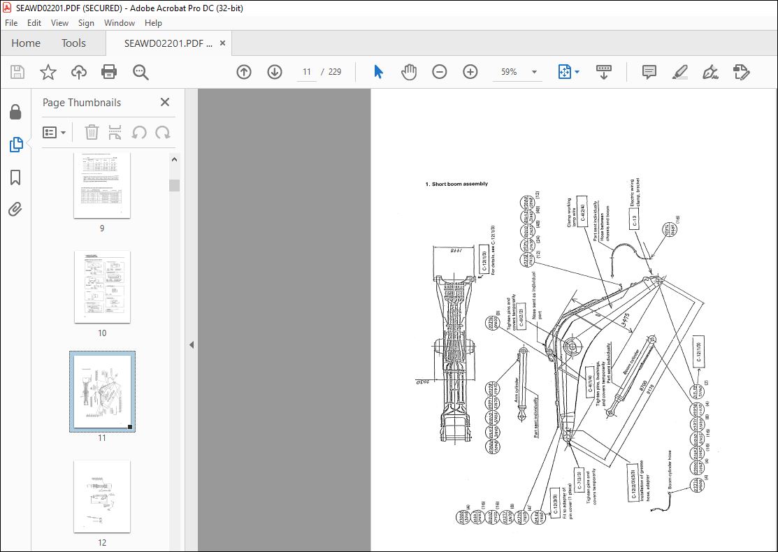


TABLE OF CONTENTS:
Komatsu PC1800-6 Hydraulic Excavator Field Assembly Manual SEAW002201 – PDF DOWNLOAD
GENERAL I 5
Specifications 5
Points regarding local assembly 6
Bolt tightening torque and bolt tightening tools 7
Separate units 10
Transportation style of loading shovel (Work equipment only) 23
Lists of parts sent individually 24
Assembly procedure, assembly equipment and schedule 49
Kit layout diagram 50
Tools and equipment to be used 51
A ASSEMBLY OF CHASSIS 57
Assembly of truck frame and axle 58
Travel motor piping 61
Idler cushion cylinder piping 63
Installation of travel motor guard and track frame under cover 64
Filling swing circuit with grease 66
Assembly of revolving frame assebly and assembly 67
Swivel travel piping 69
Swing circle grease tube piping 71
Installing of left and right ladders 76
Installation of left catwalk 77
Installation of right catwalk 78
Installation of catwalk, handrail beside operator’s cab 79
Installation of handrail for getting in and out of operator’s cab I 80
Installation of handrail at rear of operator’s cab 82
Operator’s cab front frame, handrail 83
Left dheck handrail 84
Right deck handrail 85
Installation of ladder on top of hydraulic tank 86
Installation of counterweight 87
Installation of counterweight ladder (left and right) 88
Installation of handrail on top of fuel tank, counterweight 89
Installation of fuel tank vibration stopper bracket 90
Installation of grease reel, hose, bracket 91
Installation of left cab base assembly * 92
Installation of operator’s cab assembly 97
Installation of wiper motor cover inside opereator’s cab 98
Handrail on boom foot and left pump 99
Handrail above the RH door and above the hydraulic oil tank 100
Emergency stop switch, Fuel cutting 101
A-33A Handrail above the radiator (Optional) 103
A-33B Connection of hydraulic piping operator’s cab assembly 104
A-34 Connection of window washer hose of operator’s cab assembly 107
A-35 Connection of air piping of left cab assembly 108
A-36 Connection of grease piping operator’s cab assembly 110
A-37 Wire harness (Washer tank, working lamp and operator’s cab base light) 112
A-38 Air conditioner hose, harness and piping 113
A-39 Installation of counterweight lamp (operation) 118
A-40 Start engine 119
A-41 Final tightening of swing circle mounting bolts 125
ASSEMBLY OF POWER-ASSISTED LADDER I 127
L-l Power-assisted ladder 130
C PC1800 INSTALLATION OF BACKHOE WORK EQUIPMENT I 135
Installation of boom cylinder to chassis 136
installation of boom cylinder piping 138
Bleeding air from boom cylinder 139
Boom sub-assembly 140
Installation of boom assembly 144
Installation of boom cylinder top pin 147
Connection of arm assembly to boom 149
Installation of hoses between boom and chassis 152
Installation of arm cylinder top pin 154
Bleeding air from arm cylinder 156
Installation of hydraulic between boom and arm 157
Connection of grease piping for boom 158
Connection of wiring between boom and chassis 161
Installation of hoses between boom and shassis 162
Connection of bucket assembly to arm 164
Installation of bucket link 167
Bleeding air from bucket cylinder 169
ASSEMBLY MANUAL FOR LOADING SHOVEL WORK EQUIPMENT 171
LS-1 Installation of arm cylinder tubes and hoses 172
LS-2 Installation of bucket hoses 173
LS-3 Installation of bottom dump hoses and tubes 174
LS-4 Installation of pilot solenoid valve 175
LS-5 Installation of bottom priority valve * 176
LS-6 Installation of arm pilot drain circuit I 178
LS-7 Installation of control parts 180
LS-8 Installation of horn switch I 182
LS-9 Change of arm pilot piping 183
LS-10 Removal of boom foot handrail 184
LS-11 Installation of arm cylinder bottom parts 185
LS-12 Installation of boom cylinder to machine body 186
LS-13 Installation of boom cylinder piping 188
LS-14 Installation of boom assembly 190
LS-15 Installation of boom cylinder head pins 191
LS-16 Installation of grease feed hose between machine body and boom 192
LS-17 Installation of bucket cylinder assembly 193
LS-18 Installation of arm assembly 194
Installation of arm cylinder assembly 195
Installation of hoses between boom and arm 196
Installation of bucket cylinder hoses 197
Installation of grease feed hose of bucket cylinder I 198
Installation of bucket assembly 200
Installation of bottom dump hose and grease feed hose
between arm and bucket 201
M INSPECTION AND SERVICING PROCEDURES AFTER FINNISHING
ALL THE ASSEMBLY AND INSTALLATION WORKS 203
M-l Inspecting the oil level and water level in respective sections and
refilling them ~ 204
Selection of the appropriate fuel type and lubricating oil type fitting to
the atmospheric temperature range 204
M-2 Flushing of hydraulic circuit * 206
M-3 Releasing residual pressure from hydraulic circuit * * 207
VIDEO PREVIEW OF THE MANUAL:
PLEASE NOTE:
- This is the SAME manual used by the dealers to troubleshoot any faults in your vehicle. This can be yours in 2 minutes after the payment is made.
- Contact us at [email protected] should you have any queries before your purchase or that you need any other service / repair / parts operators manual.
S.V


