

Komatsu Hydraulic Mining Shovel PC30001e Operation & Maintenance Manual – PDF DOWNLOAD
DESCRIPTION:
Komatsu Hydraulic Mining Shovel PC30001e Operation & Maintenance Manual – PDF DOWNLOAD
SERIAL NUMBER 06251
2.1SAFETY INSTRUCTIONS
2.1.1WARNINGS AND SYMBOLS
The following signs and designations are used in the manual to designate in-structions of particular importance.
WARNING
Refers to orders and prohibitions designed to prevent injury or extensive damage.
CAUTION
Refers to special information and/or orders and prohibitions directed towards preventing damage.
NOTICE
Refers to special information on how to use the machine most efficiently.
2.1.3ORGANIZATIONAL MEASURES
●The Operation,- Lubrication and Maintenance Manual must always be at hand at the place of use of the machine, e. g. by stowing them in the box provided for such purpose.
●In addition to the Operation,- Lubrication and Maintenance Manual, observe and instruct the user in all other generally applicable legal and other mandatory regulations relevant to accident prevention and environmental protection.
These compulsory regulations may also deal with the handling of hazardous substances, issuing and/or wearing of personal protective equipment, or traffic regulations.
●The Operation,- Lubrication and Maintenance Manual must be supplemented by instructions covering the duties involved in supervising and notifying special organizational features, such as job organization, working sequences or the personnel entrusted with the work.
●Personnel entrusted with work on the machine must have read the Operation,- Lubrication and Maintenance Manual and in particular the chapter on safety before beginning work. Reading the instructions after work has begun is too late. This applies especially to persons working only occasionally on the machine, e. g. during setting up or maintenance.
●Check – at least from time to time – whether the personnel is carrying out the work in compliance with the Operation,- Lubrication and Maintenance Manual and paying attention to risks and safety factors.
●For reasons of security, long hair must be tied back or otherwise secured, garments must be close-fitting and no jewellery – such as rings – may be worn. Injury may result from being caught up in the machinery or from rings catching on moving parts.
●Use protective equipment wherever required by the circumstances or by law.
●Observe all safety instructions and warnings attached to the machine.
●See to it that safety instructions and warnings attached to the machine are always complete and perfectly legible.
●In the event of safety-relevant modifications or changes in the behaviour of the machine during operation, stop the machine immediately and report the malfunction to the competent authority/person.
●Never make any modifications, additions or conversions which might affect safety without the supplier’s approval. This also applies to the installation and adjustment of safety devices and valves as well as to welding work on load-bearing elements.
●Spare parts must comply with the technical requirements specified by the manufacturer. Spare parts from original equipment manufacturers can be relied to do so.
TABLE OF CONTENTS:
Komatsu Hydraulic Mining Shovel PC30001e Operation & Maintenance Manual – PDF DOWNLOAD
1.INTRODUCTION……………………………………………………………………………….3
1.1CONTENTS OF THE BINDER ……………………………………………………………………………………………..4
1.2DIVISION OF THE BINDER …………………………………………………………………………………………………5
1.3DESIGNATED USE OF THE SHOVEL ………………………………………………………………………………….6
1.4DELIVERY OF THE SHOVEL ………………………………………………………………………………………………7
1.5EXPLANATION OF ABBREVIATIONS …………………………………………………………………………………8
1.6TABLE OF CONTENTS ………………………………………………………………………………………………………9
2.SAFETY…………………………………………………………………………………………15
2.1SAFETY INSTRUCTIONS ………………………………………………………………………………………………….16
2.1.1WARNINGS AND SYMBOLS ………………………………………………………………………………….16
2.1.2BASIC OPERATION AND DESIGNATED USE OF THE HYDRAULIC SHOVEL ……………16
2.1.3ORGANIZATIONAL MEASURES ……………………………………………………………………………17
2.1.4SELECTION AND QUALIFICATION OF PERSONNEL – BASIC RESPONSIBILITIES ……19
2.1.5SAFETY INSTRUCTIONS GOVERNING SPECIFIC OPERATIONAL PHASES …………….20
2.1.6WARNING OF SPECIAL DANGERS ……………………………………………………………………….23
2.1.7TRANSPORTING AND TOWING -RECOMMISSIONING …………………………………………..25
2.1.8SPECIAL SAFETY EQUIPMENT …………………………………………………………………………….25
2.1.9SAFETY HARNESS IN CONFORMITY WITH EN 361 (EUROPEAN STANDARD) ………..29
3.OPERATION…………………………………………………………………………………..37
3.1FOREWORD ……………………………………………………………………………………………………………………38
3.2CONSTRUCTION OF THE SHOVEL …………………………………………………………………………………..39
3.2.1OVERALL VIEW ……………………………………………………………………………………………………39
3.2.2UNDERCARRIAGE AND SUPERSTRUCTURE ………………………………………………………..42
3.2.3HYDRAULICALLY OPERATED ACCESS LADDER …………………………………………………..48
3.2.4EMERGENCY ESCAPE LADDER …………………………………………………………………………..52
3.2.5EMERGENCY ESCAPE LADDER AND ESCAPE HATCH IN THE MACHINERY HOUSE (SPECIAL EQUIPMENT) ……………………………………………………………………………………….54
3.2.6EMERGENCY MOTOR SHUTDOWN FROM GROUND MAN OR OPERATOR WARNING SYSTEM ………………………………………………………………………………………………………………56
3.2.7OPERATOR’S CAB ……………………………………………………………………………………………….58
3.3OPERATOR’S CAB – CONTROLS ……………………………………………………………………………………..62
3.3.1CONTROLS WITH BACKHOE ATTACHMENT …………………………………………………………62
3.3.2CONTROLS WITH BOTTOM DUMP BUCKET ………………………………………………………….66
1.6 TABLE OF CONTENTS INTRODUCTION
3.4 ELECTRONIC TEXT MONITORING SYSTEM ETM …………………………………………………………….. 72
3.4.1INTRODUCTION …………………………………………………………………………………………………..73
3.4.2SYSTEM COMPONENTS ………………………………………………………………………………………77
3.4.3FUNCTIONS OF THE ETM SYSTEM ………………………………………………………………………79
3.4.4SEVERAL MESSAGE CONDITIONS OCCUR AT THE SAME TIME ……………………………97
3.4.5SETTINGS OF THE TEXT DISPLAY UNIT (Z 20919) ………………………………………………..99
3.5MACHINERY HOUSE ……………………………………………………………………………………………………..114
3.6ELECTRICAL SWITCH CABINET …………………………………………………………………………………….120
3.6.1High Voltage switch cabinet, Illust. (Z 25367) ………………………………………………………….121
3.6.2Medium Voltage Switch Cabinet, illust. (Z 25369) …………………………………………………….123
3.7CHECKS BEFORE STARTING THE MAIN MOTOR …………………………………………………………..128
3.8STARTING THE MAIN DRIVE MOTOR ……………………………………………………………………………..132
3.9STOPPING THE MAIN DRIVE MOTORS …………………………………………………………………………..140
3.10MOVING THE EXCAVATOR ……………………………………………………………………………………………144
3.10.1Travel Control With Foot Pedals …………………………………………………………………………….145
3.10.2TRAVELLING INSTRUCTIONS …………………………………………………………………………….149
3.11SLEWING AND BRAKING THE SUPERSTRUCTURE ………………………………………………………..150
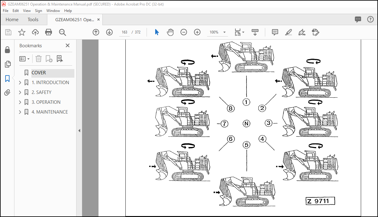
3.11.1SLEWING THE SUPERSTRUCTURE ……………………………………………………………………151
3.12WORKING WITH THE ATTACHMENT ………………………………………………………………………………154
3.12.1MACHINES EQUIPPED WITH”EURO” CONTROL SYSTEM …………………………………….154
3.12.2MACHINES EQUIPPED WITH”KMG” CONTROL SYSTEM ………………………………………155
3.12.3BOTTOM DUMP BUCKET ……………………………………………………………………………………156
3.12.4DROP BALL OPERATION ……………………………………………………………………………………157
3.12.5COMBINED OPERATION CYCLES ……………………………………………………………………….160
3.13WORKING INSTRUCTIONS …………………………………………………………………………………………….162
3.13.1STABILITY OF THE SHOVEL ……………………………………………………………………………….162
3.13.2SHOVEL OPERATION …………………………………………………………………………………………162
3.14PARKING THE SHOVEL …………………………………………………………………………………………………165
3.15OPERATING THE HEATER, VENTILATION AND AIR CONDITIONING ……………………………….166
3.15.1Air conditioning (special equipment, illust. ( Z 20423) ……………………………………………….169
3.16OPERATION OF THE LUBRICATION SYSTEM …………………………………………………………………170
3.17FIRE DETECTION AND SUPPRESSION SYSTEM …………………………………………………………….178
3.18CENTRAL REFILLING SYSTEM ………………………………………………………………………………………186
3.18.1Refilling system for hydraulic oil reservoir, grease barrels of the central lubrication system and slew ring gear lubrication system …………………………………………………………………………..187
3.18.2Refilling procedure ……………………………………………………………………………………………….189
3.18.3Refilling the grease containers of the automatic lubrication system …………………………….191
3.19 WORK ON THE LOADER ATTACHMENT …………………………………………………………………………192
3.20TRANSPORTATION AND LIFTING OF THE
SHOVEL ………………………………………………………………………………………………………………………..193
3.20.1DISASSEMBLING OF THE SHOVEL …………………………………………………………………….193
3.20.2TRANSPORTATION AND LIFTING ……………………………………………………………………….193
3.21RETRIEVAL PROCEDURE ……………………………………………………………………………………………..194
3.22SHOVEL STORAGE ……………………………………………………………………………………………………….195
3.22.1PREPARING FOR STORAGE ………………………………………………………………………………195
3.22.2ONE MONTH REPETITIVE SERVICE PERIOD ………………………………………………………195
3.22.3SIX MONTH REPETITIVE SERVICE PERIOD ………………………………………………………..196
3.22.4PREPARING FOR OPERATION …………………………………………………………………………..196
3.23TROUBLE SHOOTING ……………………………………………………………………………………………………197
3.23.1MAIN DRIVE ELECTRIC MOTOR …………………………………………………………………………197
3.23.2HYDRAULIC SYSTEM …………………………………………………………………………………………198
3.23.3FINAL DRIVES AND SWING GEAR ………………………………………………………………………199
3.23.4CRAWLER TRACKS ……………………………………………………………………………………………199
4.MAINTENANCE…………………………………………………………………………….201
4.1FOREWORD ………………………………………………………………………………………………………………….202
4.2PRECAUTIONS FOR MAINTENANCE ……………………………………………………………………………..203
4.3FLUIDS AND LUBRICANTS …………………………………………………………………………………………….205
4.3.1LUBRICANTS FOR OPERATION IN COLD AND ARCTIC CLIMATES ………………………205
4.3.2FLUIDS AND LUBRICANTS FOR MODERATE AND HOT CLIMATES ………………………206
4.3.3MAIN DRIVE ELECTRIC MOTORS – BEARING LUBRICATION ………………………………207
4.4FILLING CAPACITIES …………………………………………………………………………………………………….210
4.5STANDARD TORQUE LIST …………………………………………………………………………………………….211
4.6LUBRICATION AND MAINTENANCE SCHEDULE …………………………………………………………….212
4.6.1INITIAL SERVICING ……………………………………………………………………………………………212
4.6.2PERIODIC SERVICING INTERVALS …………………………………………………………………….212
4.6.3PERIODIC SERVICING SCHEDULE ……………………………………………………………………..213
4.6.4MAINTENANCE OF THE MAIN DRIVE MOTORS …………………………………………………..216
4.6.5REPLACEMENT OF HYDRAULIC HOSE LINES …………………………………………………….218
4.6.6PERIODIC REPLACEMENT OF SAFETY CRITICAL PARTS ……………………………………219
4.7WHEN NECESSARY ………………………………………………………………………………………………………222
4.7.1SWING CIRCLE TOOTHING LUBRICATION ………………………………………………………….223
4.7.2AUTOMATIC LUBRICATION SYSTEMS FILL GREASE CONTAINERS …………………….225
4.7.3TRACK ROLLERS AND GUIDE WHEELS – REPLACE FLOATING SEALS ………………..229
1.6 TABLE OF CONTENTS INTRODUCTION
12
4.8 EVERY 10 OPERATING HOURS OR DAILY …………………………………………………………………….. 230
4.8.1WALK – AROUND INSPECTION ……………………………………………………………………………231
4.8.2Cleaning the track group, illust. (Z 9550) …………………………………………………………………241
4.9EVERY 50 OPERATING HOURS OR WEEKLY …………………………………………………………………242
4.9.1SWING GEAR AND MOTOR ADAPTER HOUSING – CHECK OIL LEVEL ………………….243
4.9.2TRAVEL GEARS, BRAKE HOUSINGS AND MOTOR ADAPTER HOUSINGS – CHECK OIL LEVELS ……………………………………………………………………………………………………………..245
4.9.3PTO (PUMP DISTRIBUTOR GEAR) – CHECK OIL LEVEL ……………………………………….249
4.9.4Hydraulic Oil Cooler, illust. (20009)
Inspect and clean if necessary: ……………………………………………………………………………..253
4.9.5HYDRAULIC ACCESS LADDER – CHECK SAFETY SENSOR …………………………………255
4.10EVERY 250 OPERATING HOURS OR MONTHLY ……………………………………………………………..256
4.10.1SIGNAL HORN COMPRESSOR – LUBRICATE ………………………………………………………257
4.10.2HYDRAULIC OIL COOLER FAN BEARINGS – CHECK FOR LEAKAGE AND CLEAN BREATHER FILTER …………………………………………………………………………………………….257
4.10.3AUTOMATIC LUBRICATION SYSTEMS – CLEAN IN-LINE GREASE FILTER AND CHECK BREATHER FILTER …………………………………………………………………………………………….259
4.10.4CAB AIR CLEANER – CLEAN OR REPLACE FILTER ELEMENT ……………………………..263
4.10.5WINDSHIELD WASHER RESERVOIR – CHECK FLUID LEVEL ………………………………..265
4.10.6AIR CONDITIONING FOR OPERATOR’S CAB – CHECK REFRIGERANT LEVEL ………265
4.11EVERY 500 OPERATING HOURS OR MONTHLY ……………………………………………………………..266
4.11.1BATTERIES – CHECK FLUID LEVEL …………………………………………………………………….267
4.11.2CRAWLER TRACK – INSPECTION ……………………………………………………………………….269
4.12EVERY 1000 OPERATING HOURS OR EVERY 6 MONTH …………………………………………………274
4.12.1HIGH STRENGTH BOLT CONNECTIONS – CHECK TORQUE LOAD ……………………….275
4.12.2HYDRAULIC SYSTEM – FILTER SERVICE …………………………………………………………….305
4.12.3Pump Distributor Gears, Slew Gears and Travel Gears …………………………………………….319
4.12.4SIGNAL HORN COMPRESSOR – CLEAN AND LUBRICATE ……………………………………321
4.12.5HYDRAULIC TRACK TENSIONING SYSTEM – CHECK PRESSURE ACCUMULATORS ….323
4.12.6HYDRAULIC OIL COOLER – INSPECT AND LUBRICATE DOOR HINGES ………………..325
4.12.7MACHINERY HOUSE DOORS – INSPECT AND LUBRICATE DOOR HINGES …………..325
4.13EVERY 2000 OPERATING HOURS OR YEARLY ………………………………………………………………326
4.13.1HYDRAULIC SYSTEM – CHANGE OIL, REPLACE SUCTION STRAINERS AND PULSATION DAMPER …………………………………………………………………………………………327
4.13.2EMERGENCY ESCAPE LADDER – INSPECTION …………………………………………………..335
4.14EVERY 3000 OPERATING HOURS HOWEVER AT LEAST ONCE A YEAR …………………………336
4.14.1SWING GEAR AND MOTOR ADAPTER HOUSING – CHANGE OIL ………………………….337
4.14.2TRAVEL GEARS, BRAKE AND MOTOR ADAPTER HOUSINGS – CHANGE OIL ……….345
4.14.3PTO (PUMP DISTRIBUTOR GEAR) – CHANGE OIL ……………………………………………….349
4.15FIRE PREVENTION ………………………………………………………………………………………………………..354
4.16WELD REPAIRS …………………………………………………………………………………………………………….356
4.16.1PROTECTIVE MEASURES BEFORE STARTING WELD REPAIRS ON THE
INTRODUCTION 1.6 TABLE OF CONTENTS
13
UNDERCARRIAGE ……………………………………………………………………………………………..359
4.16.2PROTECTIVE MEASURES BEFORE STARTING WELD REPAIRS ON THE LOADER ATTACHMENT ……………………………………………………………………………………………………361
4.16.3PROTECTIVE MEASURES BEFORE STARTING WELD REPAIRS ON THE SUPERSTRUCTURE …………………………………………………………………………………………..363
4.16.4AFTER FINISHING THE WELD REPAIRS ON THE SUPERSTRUCTURE …………………365
IMAGES PREVIEW OF THE MANUAL:
VIDEO PREVIEW OF THE MANUAL:
PLEASE NOTE:
- This is the SAME exact manual used by your dealers to fix your vehicle.
- The same can be yours in the next 2-3 mins as you will be directed to the download page immediately after paying for the manual.
- Any queries / doubts regarding your purchase, please feel free to contact [email protected]
S.M


