

Komatsu 125E-5 Series Engine Shop Manual SEN00177-19 – PDF DOWNLOAD
IMAGES PREVIEW OF THE MANUAL:
DESCRIPTION:
Komatsu 125E-5 Series Engine Shop Manual SEN00177-19 – PDF DOWNLOAD
How to read the shop manual :
1. Composition of shop manual:
This shop manual contains the necessary technical information for services performed in a workshop.
For ease of understanding, the manual is divided into the following sections.
00. Index and foreword
This section explains the shop manuals list, table of contents, safety, and basic information.
01. Specification
This section explains the specifications of the machine.
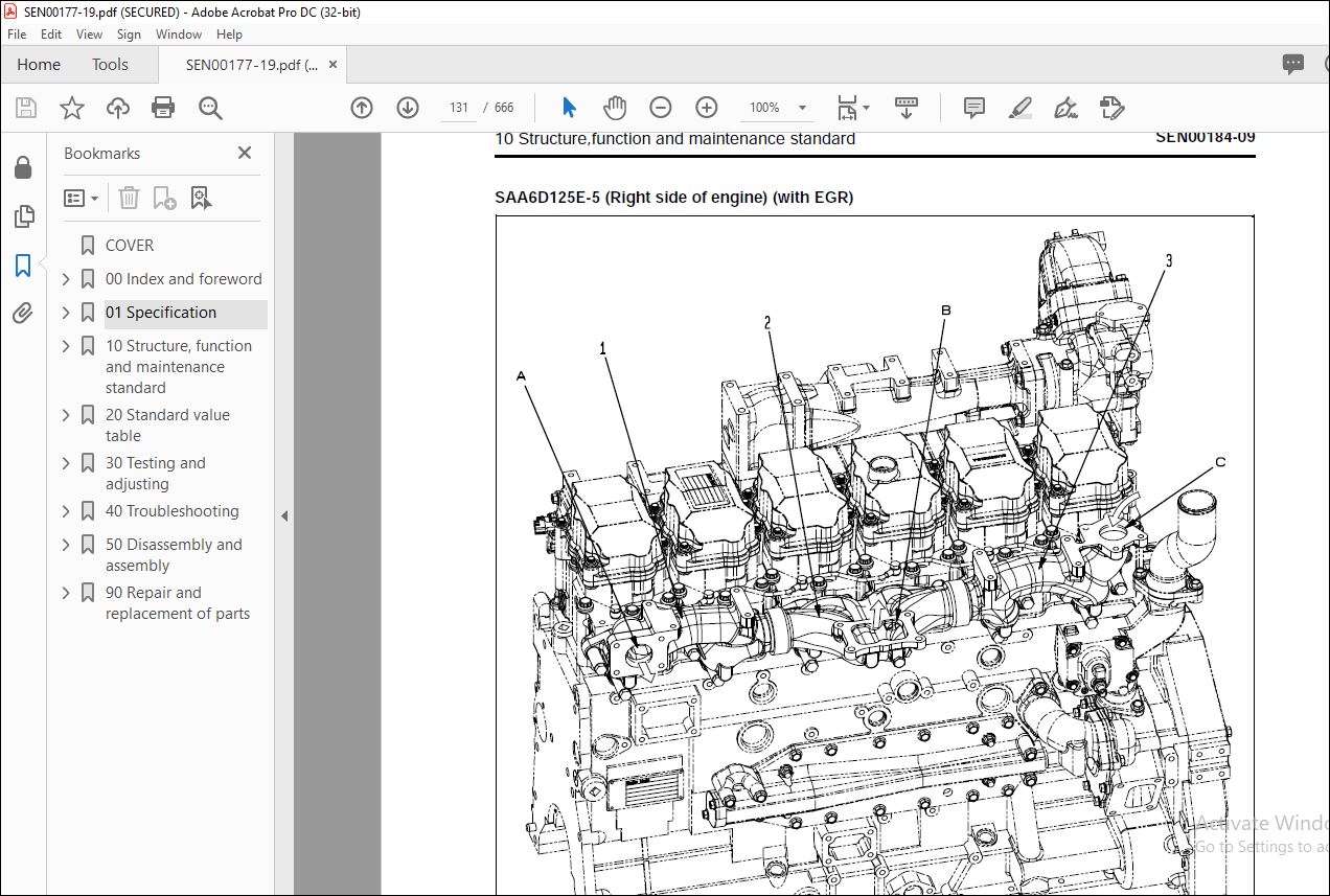
10. Structure, function and maintenance standard
This section explains the structure, function, and maintenance standard values of each component.
The structure and function sub-section explains the structure and function of each component. It
serves not only to give an understanding of the structure, but also serves as reference material for
troubleshooting. The maintenance standard sub-section explains the criteria and remedies for disassembly
and service.
20. Standard value table
This section explains the standard values for new machine and judgement criteria for testing,
adjusting, and troubleshooting. This standard value table is used to check the standard values in
testing and adjusting and to judge parts in troubleshooting.
30. Testing and adjusting
This section explains measuring instruments and measuring methods for testing and adjusting, and
method of adjusting each part. The standard values and judgement criteria for testing and adjusting
are explained in Testing and adjusting.
40. Troubleshooting
This section explains how to find out failed parts and how to repair them. The troubleshooting is
divided by failure modes. The “S mode” of the troubleshooting related to the engine may be also
explained in the Chassis volume and Engine volume. In this case, see the Chassis volume.
50. Disassembly and assembly
This section explains the special tools and procedures for removing, installing, disassembling, and
assembling each component, as well as precautions for them. In addition, tightening torque and
quantity and weight of coating material, oil, grease, and coolant necessary for the work are also
explained.
90. Diagrams and drawings (chassis volume)/Repair and replacement of parts (engine volume)
q Chassis volume
This section gives hydraulic circuit diagrams and electrical circuit diagrams.
q Engine volume
This section explains the method of reproducing, repairing, and replacing parts.
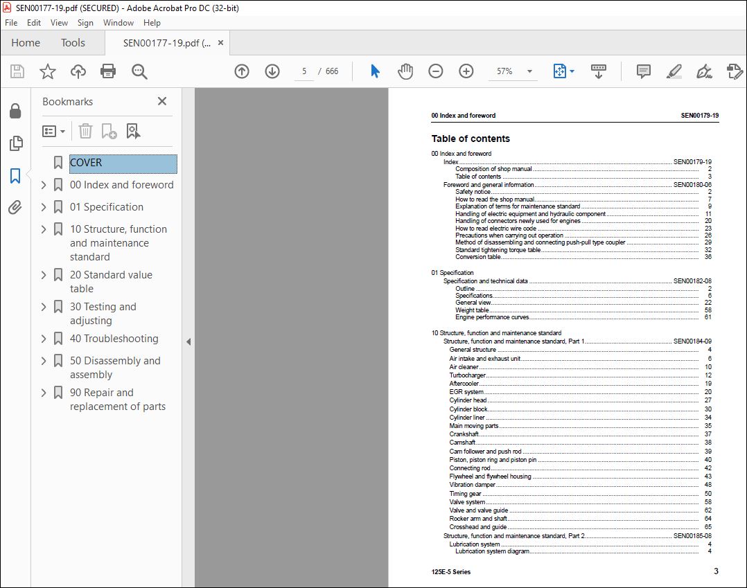
TABLE OF CONTENTS:
Komatsu 125E-5 Series Engine Shop Manual SEN00177-19 – PDF DOWNLOAD
COVER 1
00 Index and foreword 3
Index 3
Composition of shop manual 4
Table of contents 5
Foreword and general information 11
Safety notice 12
How to read the shop manual 17
Explanation of terms for maintenance standard 19
Handling of electric equipment and hydraulic component 21
Handling of connectors newly used for engines 30
How to read electric wire code 33
Precautions when carrying out operation 36
Method of disassembling and connecting push-pull type coupler 39
Standard tightening torque table 42
Conversion table 46
01 Specification 53
Specification and technical data 53
Outline 54
Specifications 58
General view 74
Weight table 110
Engine performance curves 113
10 Structure, function and maintenance standard 125
Structure, function and maintenance standard, Part 1 125
General structure 128
Air intake and exhaust unit 130
Air cleaner 134
Turbocharger 136
Aftercooler 143
EGR system 144
Cylinder head 151
Cylinder block 154
Cylinder liner 158
Main moving parts 159
Crankshaft 161
Camshaft 162
Cam follower and push rod 163
Piston, piston ring and piston pin 164
Connecting rod 166
Flywheel and flywheel housing 167
Vibration damper 172
Timing gear 174
Valve system 182
Valve and valve guide 186
Rocker arm and shaft 188
Crosshead and guide 189
Structure, function and maintenance standard, Part 2 191
Lubrication system 194
Lubrication system diagram 194
Oil pump 198
Main relief valve 199
EGR oil pump 200
Oil filter 201
Safety valve 203
Oil cooler 204
Fuel system 206
CRI system diagram 206
Outline of CRI system 208
Structure and operation of component parts 211
Fuel piping 230
Fuel filter 232
Electric priming pump 234
Engine controller cooler 235
Cooling system 236
Cooling system diagram 236
Water pump 238
Thermostat 240
Electrical equipment 242
Alternator 242
Starting motor 252
Electrical intake air heater 256
Engine controller 257
20 Standard value table 259
Standard service value table 259
Standard service value table 260
Standard service value table for testing, adjusting, and troubleshooting 260
Running-in standard and performance test standard 276
30 Testing and adjusting 287
Testing and adjusting 287
Testing and adjusting (With EGR) 289
Testing and adjusting tools list 289
Sketches of special tools 291
Testing air boost pressure 292
Testing exhaust temperature 293
Adjusting valve clearance 294
Testing compression pressure 295
Testing blow-by pressure 297
Testing engine oil pressure 298
Measuring EGR valve and bypass valve drive pressure 299
Handling fuel system parts 300
Releasing residual pressure in fuel system 300
Testing fuel pressure 301
Reduced cylinder mode operation 302
No-injection cranking 302
Testing leakage from pressure limiter and return rate from injector 303
Bleeding air from fuel circuit 306
Testing fuel system for leakage 308
Adjusting speed sensor 309
Testing and adjusting alternator belt tension 310
Handling controller voltage circuit 311
Testing and adjusting (EGR-less) 312
Testing and adjusting tools list 312
Sketches of special tools 314
Testing air boost pressure 315
Testing exhaust temperature 316
Adjusting valve clearance 317
Testing compression pressure 318
Testing blow-by pressure 320
Testing engine oil pressure 321
Handling fuel system parts 322
Releasing residual pressure in fuel system 322
Testing fuel pressure 323
Reduced cylinder mode operation 324
No-injection cranking 324
Testing leakage from pressure limiter and return rate from injector 325
Bleeding air from fuel circuit 327
Testing fuel system for leakage 329
Adjusting speed sensor 330
Testing and adjusting alternator belt tension 331
Handling controller voltage circuit 332
40 Troubleshooting 335
General information on troubleshooting 335
General information on troubleshooting 336
Points on troubleshooting 336
Error code and failure code table 338
Information in troubleshooting table 342
Troubleshooting of electrical system (E-mode), Part 1 345
Troubleshooting of electrical system (E-mode), Part 1 348
E-1 Code [111/CA111] ECM Critical Internal Failure 348
E-2 Code [115/CA115] Eng Ne and Bkup Speed Sensor Error 350
E-3 Code [122/CA122] Charge Air Press Sensor High Error 352
E-4 Code [123/CA123] Charge Air Press Sensor Low Error 354
E-5 Code [131/CA131] Throttle Sensor High Error 356
E-6 Code [132/CA132] Throttle Sensor Low Error 360
E-7 Code [135/CA135] Oil press Sensor High Error 362
E-8 Code [141/CA141] Oil press Sensor Low Error 364
E-9 Code [144/CA144] Coolant Temp Sensor High Error 366
E-10 Code [145/CA145] Coolant Temp Sensor Low Error 368
E-11 Code [153/CA153] Charge Air Temp Sensor High Error 370
E-12 Code [154/CA154] Charge Air Temp Sensor Low Error 372
E-13 Code [187/CA187] Sensor Sup 2 Volt Low Error 373
E-14 Code [221/CA221] Ambient Air Press Sensor High Error 374
E-15 Code [222/CA222] Ambient Air Press Sensor Low Error 376
E-16 Code [227/CA227] Sensor Sup 2 Volt High Error 378
E-17 Code [234/CA234] Eng Overspeed 380
E-18 Code [238/CA238] Ne Speed Sensor Sup Volt Error 382
E-19 Code [263/CA263] Fuel Temp Sensor High Error 384
E-20 Code [265/CA265] Fuel Temp Sensor Low Error 386
E-21 Code [271/CA271] PCV1 Short Error 388
E-22 Code [272/CA272] PCV1 Open Error 390
E-23 Code [273/CA273] PCV2 Short Error 392
E-24 Code [274/CA274] PCV2 Open Error 394
E-25 Code [322/CA322] Injector #1 (L/B #1) System Open/Short Error 396
E-26 Code [323/CA323] Injector #5 (L/B #5) System Open/Short Error 398
E-27 Code [324/CA324] Injector #3 (L/B #3) System Open/Short Error 400
E-28 Code [325/CA325] Injector #6 (L/B #6) System Open/Short Error 402
E-29 Code [331/CA331] Injector #2 (L/B #2) System Open/Short Error 404
E-30 Code [332/CA332] Injector #4 (L/B #4) System Open/Short Error 406
E-31 Code [342/CA342] Calibration Code Incompatibility 408
E-32 Code [351/CA351] INJ Drive Circuit Error 410
E-33 Code [352/CA352] Sensor Sup 1 Volt Low Error 412
E-34 Code [386/CA386] Sensor Sup 1 Volt High Error 414
E-35 Code [431/CA431] Idle Validation SW Low error 416
E-36 Code [432/CA432] Idle Validation Process error 418
E-37 Code [441/CA441] Battery voltage low error 418
E-38 Code [442/CA442] Battery voltage high error 419
Troubleshooting of electrical system (E-mode), Part 2 421
Troubleshooting of electrical system (E-mode), Part 2 423
E-39 Code [449/CA449] Rail Press Very High Error 423
E-40 Code [451/CA451] Rail Press Sensor High Error 424
E-41 Code [452/CA452] Rail Press Sensor Low Error 426
E-42 Code [553/CA553] Rail Press High Error 426
E-43 Code [554/CA554] Rail Press Sensor In Range Error 427
E-44 Code [559/CA559] Rail Press Low Error 428
E-45 Code [689/CA689] Eng Ne Speed Sensor Error 432
E-46 Code [731/CA731] Eng Bkup Speed Sensor Phase Error 434
E-47 Code [757/CA757] All Persistent Data Lost Error 435
E-48 Code [778/CA778] Eng Bkup Speed Sensor Error 436
E-49 Code [1228/CA1228] EGR Valve Servo Error 1 438
E-50 Code [1625/CA1625] EGR Valve Servo Error 2 439
E-51 Code [1626/CA1626] Bypass Valve Solenoid Current High Error 440
E-52 Code [1627/CA1627] Bypass Valve Solenoid Current Low Error 442
E-53 Code [1628/CA1628] Bypass Valve Servo Error 1 443
E-54 Code [1629/CA1629] Bypass Valve Servo Error 2 444
E-55 Code [1631/CA1631] BP valve Lift Position Sensor High Error 446
E-56 Code [1632/CA1632] BP valve Lift Position Sensor Low Error 448
E-57 Code [1633/CA1633] KOMNET Datalink Timeout Error 448
E-58 Code [1642/CA1642] EGR Inlet Press Sensor Low Error 449
E-59 Code [1653/CA1653] EGR Inlet Press Sensor High Error 450
E-60 Code [2185/CA2185] Throttle Sens Sup Volt High Error 452
E-61 Code [2186/CA2186] Throttle Sens Sup Volt Low Error 456
E-62 Code [2249/CA2249] Rail Press Very Low Error 457
E-63 Code [2271/CA2271] EGR Valve Lift Position Sensor High Error 458
E-64 Code [2272/CA2272] EGR Valve Lift Position Sensor Low Error 460
E-65 Code [2351/CA2351] EGR Valve Solenoid Current High Error 462
E-66 Code [2352/CA2352] EGR Valve Solenoid Current Low Error 464
E-67 Code [2555/CA2555] Grid Heater Relay Volt Low Error 465
E-68 Code [2556/CA2556] Grid Heater Relay Volt High Error 466
E-69 Code [(143)/B@BAZG] Eng Oil press Torque Derate 468
E-70 Code [(146)/B@BCNS] Eng Overheat 468
E-71 Code [(415)/B@BAZG] Eng Oil press Low Speed Derate 469
Troubleshooting of mechanical system (S-mode) 471
Troubleshooting of mechanical system (S-mode) 474
Method of using troubleshooting charts 474
S-1 Starting performance is poor 478
S-2 Engine does not start 480
S-3 Engine does not pick up smoothly 484
S-4 Engine stops during operations 485
S-5 Engine does not rotate smoothly 486
S-6 Engine lacks output (or lacks power) 487
S-7 Exhaust smoke is black (incomplete combustion) 488
S-8 Oil consumption is excessive (or exhaust smoke is blue) 490
S-9 Oil becomes contaminated quickly 491
S-10 Fuel consumption is excessive 492
S-11 Oil is in coolant (or coolant spurts back or coolant level goes down) 493
S-12 Oil pressure drops 494
S-13 Oil level rises (Entry of coolant or fuel) 495
S-14 Coolant temperature becomes too high (overheating) 497
S-15 Abnormal noise is made 498
S-16 Vibration is excessive 499
50 Disassembly and assembly 501
General information on disassembly and assembly 501
General information on disassembly and assembly 502
How to read this manual 502
Coating materials list 504
Special tools list 507
Disassembly and assembly, Part 1 (With EGR) 509
General disassembly of engine 510
General assembly of engine 525
Disassembly and assembly, Part 2 (EGR-less) 557
Disassembly and assembly, Part 2 (EGR-less) 558
General disassembly of engine 558
General assembly of engine 572
Disassembly and assembly, Part 3 605
Disassembly and assembly, Part 3 606
Removal and installation of fuel supply pump unit 606
Replacement of oil seal of engine mounted on machine 608
90 Repair and replacement of parts 613
Information related to repair and replacement 613
Flowchart 614
Special tool table 616
Special tool sketch 618
Parts related to cylinder head 621
Part names related to cylinder head 622
Testing and inspection of cylinder head 623
Pressure test of cylinder head 625
Replacement of valve guide 625
Replacement of valve seat insert 626
Replacement of crosshead guide 633
Repair of valve by grinding 634
Parts related to cylinder block 637
Part names related to cylinder block 638
Testing and inspection of cylinder block 639
Part names related to crankshaft 642
Testing and inspection of crankshaft 643
Part names related to connecting rod 644
Testing and inspection of connecting rod 645
Replacement of flywheel ring gear 647
Replacement of camshaft gear 647
Replacement of main bearing metal cap 648
Replacement of connecting rod small end bushing 650
Replacement of cam bushing 651
Replacement of engine rear seal 653
Replacement of wear sleeve (when sleeve is installed) 657
Repair of crankshaft by grinding 658
VIDEO PREVIEW OF THE MANUAL:
PLEASE NOTE:
- This is not a physical manual but a digital manual – meaning no physical copy will be couriered to you. The manual can be yours in the next 2 mins as once you make the payment, you will be directed to the download page IMMEDIATELY.
- This is the same manual used by the dealers inorder to diagnose your vehicle of its faults.
- Require some other service manual or have any queries: please WRITE to us at [email protected]
S.V


