

JLG 1230ES Service & Maintenance Manual 3121222 – PDF DOWNLOAD
FILE DETAILS:
JLG 1230ES Service & Maintenance Manual 3121222 – PDF DOWNLOAD
Language : English
Pages : 198
Downloadable : Yes
File Type : PDF
DESCRIPTION:
JLG 1230ES Service & Maintenance Manual 3121222 – PDF DOWNLOAD
GENERAL
This section contains the general safety precautions which must be observed during maintenance of the aerial platform. It is of utmost importance that maintenance personnel pay strict attention to these warnings and precautions to avoid possible injury to themselves or others, or damage to the equipment. A maintenance program must be followed to ensure that the machine is safe to operate.
- The specific precautions to be observed during maintenance are inserted at the appropriate point in the manual. These precautions are, for the most part, those that apply when servicing hydraulic and larger machine component parts.
- Your safety, and that of others, is the first consideration when engaging in the maintenance of equipment. Always be conscious of weight. Never attempt to move heavy parts without the aid of a mechanical device.
- Do not allow heavy objects to rest in an unstable position. When raising a portion of the equipment, ensure that adequate support is provided.
B HYDRAULIC SYSTEM SAFETY
It should be noted that the machines hydraulic systems operate at extremely high potentially dangerous pressures. Every effort should be made to relieve any system pressure prior to disconnecting or removing any portion of the system. Relieve system pressure by cycling the applicable control several times with the engine stopped and ignition on, to direct any line pressure back into the reservoir. Pressure feed lines to system components can then be disconnected with minimal fluid loss.
MAINTENANCE
- NO SMOKING IS MANDATORY. NEVER REFUEL DURING ELECTRICAL STORMS. ENSURE THAT FUEL CAP IS CLOSED AND SECURE AT ALL OTHER TIMES.
- REMOVE ALL RINGS, WATCHES AND JEWELRY WHEN PERFORMING ANY MAINTENANCE.
- DO NOT WEAR LONG HAIR UNRESTRAINED, OR LOOSE-FITTING CLOTHING AND NECKTIES WHICH ARE APT TO BECOME CAUGHT ON OR ENTANGLED IN EQUIPMENT.
- OBSERVE AND OBEY ALL WARNINGS AND CAUTIONS ON MACHINE AND IN SERVICEMANUAL.
- KEEP OIL, GREASE, WATER, ETC. WIPED FROM STANDING SURFACES AND HAND HOLDS.
- USE CAUTION WHEN CHECKING A HOT, PRESSURIZED COOLANT SYSTEM.
- NEVER WORK UNDER AN ELEVATED BOOM UNTIL BOOM HAS BEEN SAFELY RESTRAINED FROM ANY MOVEMENT BY BLOCKING OR OVERHEAD SLING, OR BOOM SAFETY PROP HAS BEEN ENGAGED.
- BEFORE MAKING ADJUSTMENTS, LUBRICATING OR PERFORMING ANY OTHER MAINTENANCE, SHUT OFF ALL POWER CONTROLS.
- BATTERY SHOULD ALWAYS BE DISCONNECTEDDURING REPLACEMENT OF ELECTRICAL COMPONENTS
- KEEP ALL SUPPORT EQUIPMENT AND ATTACHMENTS STOWED IN THEIR PROPER PLACE.
- USE ONLY APPROVED, NONFLAMMABLE CLEANING SOLVENTS.
IMAGES PREVIEW OF THE MANUAL:
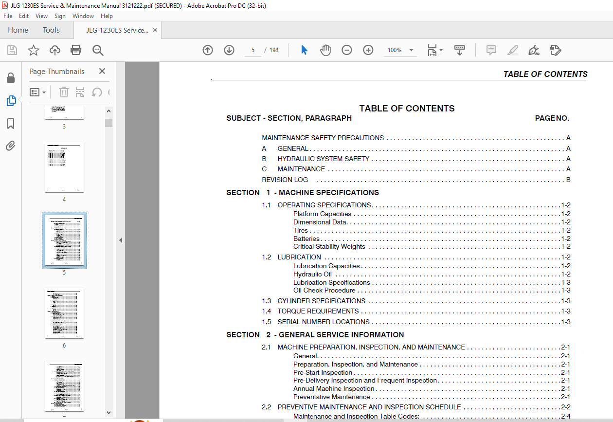
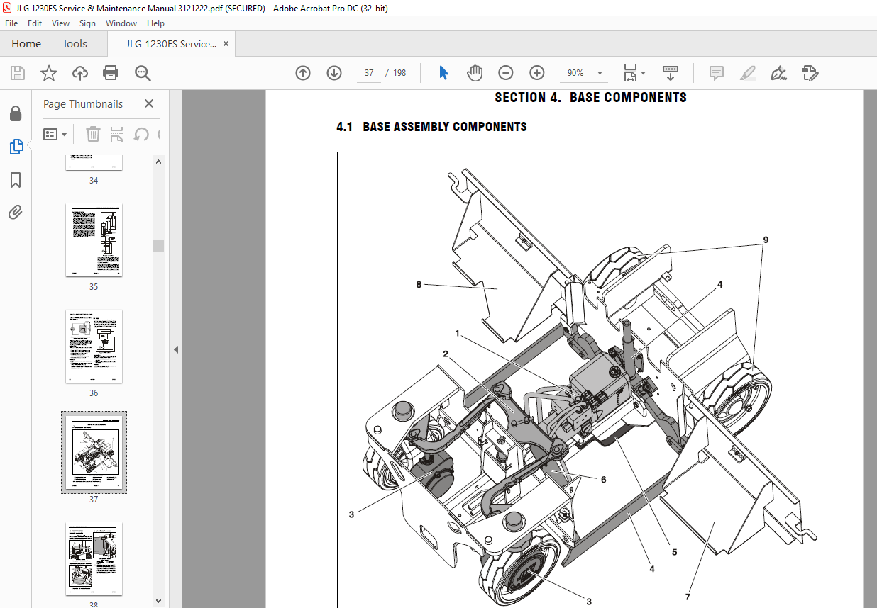
TABLE OF CONTENTS:
JLG 1230ES Service & Maintenance Manual 3121222 – PDF DOWNLOAD
A GENERAL 3
B HYDRAULIC SYSTEM SAFETY 3
C MAINTENANCE 3
SECTION 1 MACHINE SPECIFICATIONS 13
1 1 OPERATING SPECIFICATIONS 14
Platform Capacities 14
Dimensional Data 14
Tires 14
Batteries 14
Critical Stability Weights 14
1 2 LUBRICATION 14
Lubrication Capacities 14
Hydraulic Oil 14
Lubrication Specifications 15
Oil Check Procedure 15
1 3 CYLINDER SPECIFICATIONS 15
1 4 TORQUE REQUIREMENTS 15
1 5 SERIAL NUMBER LOCATIONS 15
SECTION 2 GENERAL SERVICE INFORMATION 23
2 1 MACHINE PREPARATION, INSPECTION, AND MAINTENANCE 23
General 23
Preparation, Inspection, and Maintenance 23
Pre-Start Inspection 23
Pre-Delivery Inspection and Frequent Inspection 23
Annual Machine Inspection 23
Preventative Maintenance 23
2 2 PREVENTIVE MAINTENANCE AND INSPECTION SCHEDULE 24
Maintenance and Inspection Table Codes: 26
Footnotes: 26
2 3 SERVICING AND MAINTENANCE GUIDELINES 27
General 27
Safety and Workmanship 27
Cleanliness 27
Components Removal and Installation 27
Component Disassembly and Reassembly 27
Pressure-Fit Parts 27
Bearings 28
Gaskets 28
Bolt Usage and Torque Application 28
Hydraulic Lines and Electrical Wiring 28
Hydraulic System 28
Lubrication and Servicing 28
Batteries 28
2 4 LUBRICATION INFORMATION 28
Hydraulic System 28
Lubrication Specifications 29
Hydraulic Oil 29
Changing Hydraulic Oil 29
SECTION 3 THEORY OF OPERATION – 1230ES 31
3 1 OVERVIEW 31
3 2 MODES OF OPERATION 31
Ground Mode 31
Platform mode 31
3 3 CAN COMMUNICATIONS 31
3 4 CONTROLS & SENSORS 33
Elevation 33
Joystick 33
Tilt 33
3 5 TRACTION 33
Personalities 34
Interlocks 34
3 6 PUMP/LIFT/MAST 35
Personalities 36
Interlocks 36
3 7 STEER 36
Personalities 36
Interlocks 36
SECTION 4 BASE COMPONENTS 37
4 1 BASE ASSEMBLY COMPONENTS 37
4 2 BASE FRAME COVERS 38
Base Top Cover – Installation 38
Step Plate/Battery Charger Cover – Installation 38
Battery Tray/Side Door – Installation 38
4 3 WHEELS AND TIRES – DRIVE AND REAR 39
Tire Wear and Damage 39
Wheel and Tire Replacement 39
Wheel Installation 39
4 4 REAR WHEEL HUB – INSTALLATION 40
4 5 STEERING LINKAGE ASSEMBLY – INSTALLATION 41
4 6 STEER CYLINDER – SERVICING 42
Steer Cylinder Disassembly 43
Hydraulic Cylinder Component Inspection 44
Steer Cylinder – Assembly 44
4 7 DRIVE MOTOR/SPINDLE ASSEMBLY – INSTALLATION 46
4 8 WHEEL DRIVE ASSEMBLY – SERVICING 47
Drive Motor Electrical Evaluation 47
Roll And Leak Testing 48
Oil Type & Capacity 48
Drive Motor Power Harness Routing 48
Wheel Drive Brake – Manual Disengage Procedure 49
Wheel Drive Motor Assembly – Removal From Machine 50
Drive Motor Disassembly 51
Drive Motor Inspection and Servicing 52
Drive Motor – Reassembly 53
Main Gear Box Disassembly 54
Input Carrier Disassembly 55
Hub – Disassembly 56
Spindle Disassembly 57
Spindle Sub-Assembly 58
Hub Sub-Assembly 60
Input Carrier Sub-Assembly 61
Main Gear Box Sub-Assembly 62
Motor Assembly 64
4 9 HYDRAULIC PUMP/MOTOR/VALVE ASSEMBLY – SERVICE PROCEDURE 65
Common Difficulties 65
Pump Components 68
Hydraulic System Pressure Check Port 68
Hydraulic System Pressure Settings 69
Pump/Motor/Valve Assembly – Removal/Installation 70
Motor Cover/Motor Installation 72
Preventative Maintenance – Brush Wear – Dust Removal Procedure 72
Motor Brush Installation 72
4 10 POT HOLE PROTECTION SYSTEM 73
SECTION 5 CONTROL COMPONENTS 77
5 1 CONTROL COMPONENTS OVERVIEW 77
5 2 CONTROL COMPONENTS – SERVICE 78
Main Power Contactor Relay 78
Elevation Limit Switch 78
Ground Alarm 78
Warning Beacon – Frame Mounted 78
Manual Brake Release Switch 79
AC Power – Breaker Box Installation (CE Specification Machines ONLY) 79
5 3 TRACTION SYSTEM 80
Common Traction System Difficulties 80
5 4 POWER MODULE – P/N-1600346 83
Removal 83
Installation 83
Power Module Electrical Evaluation 84
Power Module Diagnostics 85
5 5 Power Module – P/N-1001092456 87
ZAPI Power Module Electrical Evaluation 88
5 6 GROUND CONTROL MODULE – SERVICE PROCEDURE 89
Ground Control Station 89
Printed Circuit Board (PCB) Replacement 89
5 7 PLATFORM CONTROL STATION – SERVICE INFORMATION 92
Platform Control Station Assembly 92
Upper Control Box – Component Replacement 92
Lower Control Box – Component Replacement 94
5 8 Battery/Battery Charger 95
Battery Maintenance and Safety Practices 95
Battery Installation 96
5 9 BATTERY CHARGER – INSTALLATION 96
Battery Charger Troubleshooting 97
5 10 BATTERY CHARGER/INVERTER (OPTION) – INSTALLATION 100
SECTION 6 MAST COMPONENTS 101
6 1 MAST COMPONENTS OVERVIEW 101
6 2 PLATFORM TOOL TRAY – INSTALLATION 102
6 3 MAST COVER PLATE – INSTALLATION 102
6 4 PLATFORM AC RECEPTACLE BOX – INSTALLATION 102
6 5 MAST ASSEMBLY – COMPONENTS 103
6 6 PLATFORM ASSEMBLY 104
Platform – Extending Mast Unpowered 104
Platform Removal 104
Platform Installation 105
6 7 MAST ASSEMBLY 106
Mast Removal 107
Mast Disassembly 108
Mast – Reassembly 109
Mast Installation 110
Multi-Stage Hydraulic Cylinder – Cylinder Bleeding Procedure 112
Mast Installation Completion 112
6 8 MULTI-STAGE HYDRAULIC CYLINDER – SERVICING 113
Overview 113
Hydraulic Cylinder – Disassembly 115
Hydraulic Cylinder Component Inspection 117
Hydraulic Cylinder – Assembly 117
Hydraulic Cylinder Assembly Testing 118
SECTION 7 JLG CONTROL SYSTEM 119
7 1 ELECTRONIC CONTROL SYSTEM 119
To Connect the Hand Held Analyzer: 119
Using the Analyzer: 119
Changing the Access Level of the Hand Held Analyzer: 120
Machine Setup 121
Diagnostic Trouble Codes (DTC) 121
7 2 MACHINE CONFIGURATION PROGRAMMING INFORMATION 127
7 3 MACHINE PERSONALITY – ADJUSTMENT SETTINGS 129
7 4 TILT SENSOR CALIBRATION 130
Ground Module Software Version 1 5 130
Ground Module Software Version 1 4 130
Calibration Failures 130
7 5 TILT SENSOR ELECTRICAL EVALUATION 131
7 6 ELEVATION ANGLE SENSOR ELECTRICAL EVALUATION 131
Tilt vs Allowed Height Evaluation 131
7 7 ELEVATION SENSOR CALIBRATION 131
SECTION 8 DIAGNOSTIC TROUBLE CODES 133
8 1 Introduction 133
8 2 X-CONNECTOR REFERENCES 133
8 3 DTC Index 133
8 4 DTC Check Tables 137
0-0 Help Comments 137
2-1 Power-Up 138
2-2 Platform Controls 138
2-3 Ground Controls 140
2-5 Function Prevented 140
3-1 Line Contactor Open Circuit 142
3-2 Line Contactor Short Circuit 142
3-3 Ground Output Driver 143
4-2 Thermal Limit (SOA) 145
4-4 Battery Supply 146
6-6 Communication 146
6-7 Accessory 148
7-7 Electric Motor 148
8-1 Tilt Sensor 150
8-2 Platform Load Sense 150
9-9 Hardware 150
SECTION 9 GENERAL ELECTRICAL INFORMATION & SCHEMATICS 155
9 1 GENERAL 155
9 2 MULTIMETER BASICS 155
Grounding 155
Backprobing 155
Min/Max 155
Polarity 155
Scale 155
Continuity Measurement Over Long Distances 158
Requirements: 158
Procedure 158
9 3 ELECTRICAL SWITCH TESTING 159
Basic Check 159
Limit Switches 159
Automatic Switches 160
Switch Wiring – Low Side, High Side 160
9 4 APPLYING SILICONE DIELECTRIC COMPOUND TO AMP CONNECTORS 161
Assembly 162
Disassembly 164
Wedge Lock 164
Service – Voltage Reading 164
9 5 WORKING WITH DEUTSCH CONNECTORS 166
DT/DTP Series Assembly 166
DT/DTP Series Disassembly 166
HD30/HDP20 Series Assembly 166
HD30/HDP20 Series Disassembly 167
9 6 X-CONNECTOR REFERENCES 167
9 7 CONNECTOR LOADING DIAGRAMS 168
9 8 X-CONNECTOR ID INDEX 171
9 9 MACHINE LOCATION OF COMPONENT X-CONNECTORS 174
9 10 ELECTRICAL LAYOUT AND SCHEMATICS 176
9 11 PIN INPUT/OUTPUT TYPES 187
9 12 AC POWER RECEPTACLES AND WIRING (PLATFORM) – CE SPEC MACHINES ONLY 192
9 12 HYDRAULIC SCHEMATIC 196
VIDEO PREVIEW OF THE MANUAL:
PLEASE NOTE:
- This is the SAME exact manual used by your dealers to fix your vehicle.
- The same can be yours in the next 2-3 mins as you will be directed to the download page immediately after paying for the manual.
- Any queries / doubts regarding your purchase, please feel free to contact [email protected]
S.M


