

JLG 1100SB Service & Maintenance Manual 3121265 – PDF DOWNLOAD
FILE DETAILS:
JLG 1100SB Service & Maintenance Manual 3121265 – PDF DOWNLOAD
Language : English
Pages :444
Downloadable : Yes
File Type : PDF
DESCRIPTION:
JLG 1100SB Service & Maintenance Manual 3121265 – PDF DOWNLOAD
GENERAL
This section contains the general safety precautions which must be observed during maintenance of the aerial platform. It is of utmost importance that maintenance personnel pay strict attention to these warnings and precautions to avoid possible injury to themselves or others, or damage to the equipment. A maintenance program must be followed to ensure that the machine is safe to operate.
- The specific precautions to be observed during maintenance are inserted at the appropriate point in the manual. These precautions are, for the most part, those that apply when servicing hydraulic and larger machine component parts.
- Your safety, and that of others, is the first consideration when engaging in the maintenance of equipment. Always be conscious of weight. Never attempt to move heavy parts without the aid of a mechanical device.
- Do not allow heavy objects to rest in an unstable position. When raising a portion of the equipment, ensure that adequate support is provided.
B HYDRAULIC SYSTEM SAFETY
It should be noted that the machines hydraulic systems operate at extremely high potentially dangerous pressures. Every effort should be made to relieve any system pressure prior to disconnecting or removing any portion of the system. Relieve system pressure by cycling the applicable control several times with the engine stopped and ignition on, to direct any line pressure back into the reservoir. Pressure feed lines to system components can then be disconnected with minimal fluid loss.
MAINTENANCE
- NO SMOKING IS MANDATORY. NEVER REFUEL DURING ELECTRICAL STORMS. ENSURE THAT FUEL CAP IS CLOSED AND SECURE AT ALL OTHER TIMES.
- REMOVE ALL RINGS, WATCHES AND JEWELRY WHEN PERFORMING ANY MAINTENANCE.
- DO NOT WEAR LONG HAIR UNRESTRAINED, OR LOOSE-FITTING CLOTHING AND NECKTIES WHICH ARE APT TO BECOME CAUGHT ON OR ENTANGLED IN EQUIPMENT.
- OBSERVE AND OBEY ALL WARNINGS AND CAUTIONS ON MACHINE AND IN SERVICEMANUAL.
- KEEP OIL, GREASE, WATER, ETC. WIPED FROM STANDING SURFACES AND HAND HOLDS.
- USE CAUTION WHEN CHECKING A HOT, PRESSURIZED COOLANT SYSTEM.
- NEVER WORK UNDER AN ELEVATED BOOM UNTIL BOOM HAS BEEN SAFELY RESTRAINED FROM ANY MOVEMENT BY BLOCKING OR OVERHEAD SLING, OR BOOM SAFETY PROP HAS BEEN ENGAGED.
- BEFORE MAKING ADJUSTMENTS, LUBRICATING OR PERFORMING ANY OTHER MAINTENANCE, SHUT OFF ALL POWER CONTROLS.
- BATTERY SHOULD ALWAYS BE DISCONNECTEDDURING REPLACEMENT OF ELECTRICAL COMPONENTS
- KEEP ALL SUPPORT EQUIPMENT AND ATTACHMENTS STOWED IN THEIR PROPER PLACE.
- USE ONLY APPROVED, NONFLAMMABLE CLEANING SOLVENTS.
IMAGES PREVIEW OF THE MANUAL:


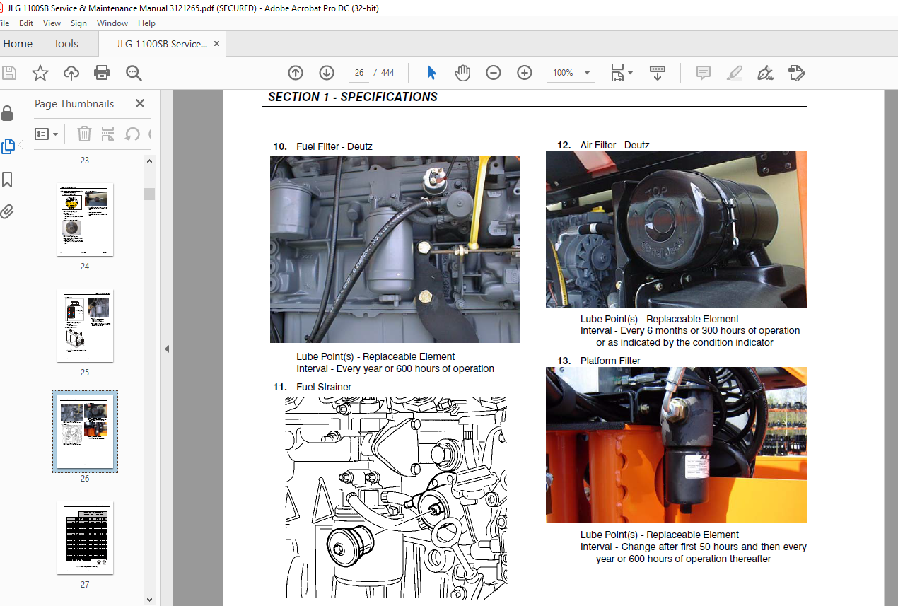
TABLE OF CONTENTS:
JLG 1100SB Service & Maintenance Manual 3121265 – PDF DOWNLOAD
Section A INTRODUCTION – MAINTENANCE SAFETY PRECAUTIONS 3
A General 3
B Hydraulic System Safety 3
C Maintenance 3
Section 1 SPECIFICATIONS 17
1 1 Capacities 17
1 2 Tires 17
1 3 Engine Data 17
Engine Data 17
1 4 Specifications and Performance Data 17
Reach Specifications 17
Dimensional Data 18
Chassis 18
1 5 Torque Requirements 18
1 6 Hydraulic Oil 19
1 7 Major Component Weights 21
1 8 Pressure Settings 21
1 9 Lubrication and Operator Maintenance 23
Section 2 GENERAL 33
2 1 Machine Preparation, Inspection, and Maintenance 33
General 33
Preparation, Inspection, and Maintenance 33
Pre-Start Inspection 33
Pre-Delivery Inspection and Frequent Inspection 33
Annual Machine Inspection 33
Preventative Maintenance 33
2 2 Service and Guidelines 34
General 34
Safety and Workmanship 34
Cleanliness 34
Components Removal and Installation 34
Component Disassembly and Reassembly 35
Pressure-Fit Parts 35
Bearings 35
Gaskets 35
Bolt Usage and Torque Application 35
Hydraulic Lines and Electrical Wiring 35
Hydraulic System 35
Lubrication 35
Battery 35
Lubrication and Servicing 35
2 3 Lubrication and Information 35
Hydraulic System 35
Hydraulic Oil 36
Changing Hydraulic Oil 36
Lubrication Specifications 36
2 4 Cylinder Drift Test 36
Platform Drift 36
Cylinder Drift 37
2 5 Pins and Composite Bearing Repair Guidelines 37
2 6 Welding on JLG Equipment 37
Do the Following When Welding on JLG Equipment 37
Do NOT Do the Following When Welding on JLG Equipment 37
Section 3 CHASSIS & TURNTABLE 43
3 1 Tires & Wheels 43
Tire Inflation 43
Tire Damage 43
Wheel and Tire Replacement 43
Wheel Installation 43
3 2 Extending Axles 44
3 3 Axle Limit Switch Adjustment Procedure 44
3 4 Drive System 45
3 5 Steering Control System 45
3 6 Drive/Steering Speed Control 46
3 7 Traction Control System 46
3 8 Drive Orientation System 46
3 9 Oscillating Axle System 56
3 10 Oscillating Axle Bleeding Procedure and Lockout Test 56
Lockout Cylinder Bleeding 56
Oscillating Axle Lockout Test 57
3 11 Drive Hub – Bonfiglioli 58
Product Identification 58
Hydraulic Motor Installation 58
Installation of the Wheel Drive on the Machine 58
Start Up and Running In 58
General Information 59
Connecting the Brake 59
Filling-up the Gearbox with Lubricating Oil 59
Gearbox Disengagement 61
Maintenance Information 63
Changing the Lubricating oil 63
Troubleshooting 64
Disassembly Information 64
Disassembly Procedure 64
Inspection of Parts 72
Assembly 73
Final Test and Reinstallation 83
3 12 Drive Hub – Reggiana Riduttori 88
Symbol Nomenclature 88
Tools 88
Disassembly 93
Assembly 97
3 13 Swing Drive 103
Roll and Leak Testing 103
Tightening and Torquing Bolts 103
Motor Control Valve Disassembly 104
Motor and Brake Disassembly 105
Main Disassembly 106
Hub-Shaft Disassembly 107
Carrier Disassembly 108
Hub-Shaft Sub-Assembly 109
Carrier Sub-Assembly 110
Main Assembly 112
Motor and Brake Assembly 114
Motor Control Valve Assembly 115
3 14 Swing Brake 116
Pre-Installation Checks 116
Installation 117
Maintenance 117
Disassembly 117
Examination 117
Assembly 117
3 15 Swing Motor 119
Disassembly and inspection 119
Assembly 126
One Piece Stator Construction 133
3 16 Procedure For Setting Gear Backlash 134
3 17 Swing Drive Lubrication 135
3 18 Swing Bearing 136
Turntable Bearing Mounting Bolt Condition Check 136
Wear Tolerance 139
Swing Bearing Removal 139
Swing Bearing Installation 141
Swing Bearing Torque Values 142
3 19 Swing Speed Proportioning 143
3 20 Chassis Tilt Indicator System 143
3 21 Rotary Coupling 144
3 22 Generator 148
Every 250 hours 148
Every 500 hours 148
Overload Protection 149
Inspecting Brushes, Replacing Brushes, and Cleaning Slip Rings 149
3 23 Auxiliary Power System 151
3 24 Cold Weather Package 153
3 25 Engine 153
Glow Plugs 153
Checking Oil Level 153
Changing Engine Oil 153
Changing the Oil Filter 154
Replacing the Fuel Filter 155
Cleaning the Fuel Strainer 155
3 26 Deutz EMR 2 156
3 27 Bio Fuel in Deutz Engines 169
General 169
Bio Fuel 169
Biological Contamination In Fuels 170
Section 4 BOOM & PLATFORM 171
4 1 Boom Systems 171
Broken Cable Indicator System 171
Platform Control Enable System 171
Transport Position Sensing System 171
Beyond Transport – Drive Speed Cutback System 171
Jib Stow System 172
Envelope Tracking System 172
Moment Control System 173
Boom Control System (BCS) Functional Check (Push to Test) System 173
Controlled Arc System 173
Controlled Boom Angle System 174
Envelope Tracking 174
Slow Down System 174
Dual Capacity System 175
Electronic Platform Leveling 175
Boom Control Select 176
4 2 Boom Assembly 177
Removal 177
Disassembly 186
Assembly 188
4 3 Jib Rotator Orientation 199
4 4 Jib Lift End of Stroke Dampening 199
4 5 Load Sensing Pin Removal and Installation 199
4 6 Hose Routing Procedure 214
4 7 Wire Rope 214
Inspection 214
Three Month Inspection 214
Seven Year Inspection 214
Replacement Criteria 214
Wire Rope Tensioning Procedure 215
4 8 Broken Boom Cable Proximity Switch 219
Adjusting the Proximity Switch 219
4 9 Electronic Platform Leveling 219
Description 219
Normal Operation 220
4 10 Rotary Actuator 221
Theory of Operation 221
Required Tools 221
Disassembly 224
Inspection 228
Assembly 228
Bleeding After Installation 233
Section 5 HYDRAULICS 235
5 1 Lubricating O-Rings in the Hydraulic System 235
Cup and Brush 235
Dip Method 236
Spray Method 236
Brush-on Method 236
5 2 Cylinder Repair 237
Disassembly 237
Cleaning and Inspection 245
Assembly 247
5 3 Hydraulic Tank 257
5 4 Pressure Setting Procedure 257
Set Up of the Function Pump 257
Adjustments made at the Main Valve Bank 258
Adjustments Made at the Frame Valve Bank 259
Adjustments Made at the Platform Valve Bank 263
5 5 Drive Pumps 264
Troubleshooting Procedure 264
Charge Pressure Relief Valve Adjustment 267
Mechanical Centering of Pump 268
Hydraulic Centering of Control Modules 268
High Pressure Relief Valve Adjustments 269
Removal and inspection of charge pump 269
Routine Maintenance 270
Removal and Installation of Shaft Seal 272
5 6 Function Pump 273
Spare Parts 273
Sealing the Drive Shaft 274
Disassembly and Assembly of the Complete Unit 275
Assembly 278
Adjustments 279
Tightening Torques 279
Pump Control Disassembly For Cleaning 281
5 7 Drive & Function Pump Start Up Procedures 283
Start-Up Procedure 283
Section 6 JLG CONTROL SYSTEM 285
6 1 Introduction 285
6 2 CANbus Communications 286
6 3 Calibration Instructions 288
6 4 To Connect the JLG Control System Analyzer 298
6 5 Using the Analyzer 298
6 6 Changing the Access Level of the Hand Held Analyzer 299
6 7 Adjusting Parameters Using the Hand Held Analyzer 300
6 8 Machine Setup 300
6 9 Machine Personality Settings/ Function Speeds 305
6 10 Machine Orientation When Setting Function Speeds 309
Test Notes 309
6 11 System Test 310
Test from the Platform 310
Test from the Ground Station 313
6 12 Calibrating Steer 328
6 13 Calibrating Drive 331
6 14 Electronic Platform Leveling 334
Platform Leveling Fault Warning 334
Fault Response 334
CAN Errors 335
Additional Platform and Jib Valves 335
Platform Leveling Calibration Procedure 336
6 15 Calibrating Platform Level 337
STEP 1: SETTING THE PLATFORM VALVE MINIMUMS 337
STEP 2: CALIBRATING THE PLATFORM LEVEL SENSORS 338
STEP 3: BLEEDING THE PLATFORM VALVES 339
STEP 4: CALIBRATING THE PLATFORM LEVEL UP AND DOWN VALVE CRACKPOINTS 340
6 16 Calibrating Lift Crack Point 341
6 17 Calibrating Telescope Crack point 344
6 18 Calibrating Tilt Sensor 347
6 19 Calibrating the Boom Sensors 349
Boom Control System Check Procedure 362
6 20 CANbus Troubleshooting 390
CANbus Communication Failure 397
Load Moment Pin Troubleshooting 410
Section 7 BASIC ELECTRICAL INFORMATION & SCHEMATICS 415
7 1 General 415
7 2 Multimeter Basics 415
Grounding 415
Backprobing 415
Min/Max 415
Polarity 415
Scale 415
Voltage Measurement 415
Resistance Measurement 416
Continuity Measurement 416
Current Measurement 417
7 3 Applying Silicone Dielectric Compound to Electrical Connections 417
7 4 AMP Connector 418
Applying Silicone Dielectric Compound to AMP Connectors 418
Assembly 418
Disassembly 420
Wedge Lock 420
Service – Voltage Reading 420
7 5 Deutsch Connectors 422
DT/DTP Series Assembly 422
DT/DTP Series Disassembly 422
HD30/HDP20 Series Assembly 423
HD30/HDP20 Series Disassembly 423
VIDEO PREVIEW OF THE MANUAL:
PLEASE NOTE:
- This is the same manual used by the DEALERSHIPS to SERVICE your vehicle.
- The manual can be all yours – Once payment is complete, you will be taken to the download page from where you can download the manual. All in 2-5 minutes time!!
- Need any other service / repair / parts manual, please feel free to contact us at heydownloadss @gmail.com . We may surprise you with a nice offer
S.M


