

JLG 10MSP Vertical Lift Service & Maintenance Manual 3121228 – PDF DOWNLOAD
FILE DETAILS:
JLG 10MSP Vertical Lift Service & Maintenance Manual 3121228 – PDF DOWNLOAD
Language : English
Pages :154
Downloadable : Yes
File Type : PDF
DESCRIPTION:
JLG 10MSP Vertical Lift Service & Maintenance Manual 3121228 – PDF DOWNLOAD
GENERAL
This section contains the general safety precautions which must be observed during maintenance of the aerial platform. It is of utmost importance that maintenance personnel pay strict attention to these warnings and precautions to avoid possible injury to themselves or others, or damage to the equipment. A maintenance program must be followed to ensure that the machine is safe to operate.
- The specific precautions to be observed during maintenance are inserted at the appropriate point in the manual. These precautions are, for the most part, those that apply when servicing hydraulic and larger machine component parts.
- Your safety, and that of others, is the first consideration when engaging in the maintenance of equipment. Always be conscious of weight. Never attempt to move heavy parts without the aid of a mechanical device.
- Do not allow heavy objects to rest in an unstable position. When raising a portion of the equipment, ensure that adequate support is provided.
B HYDRAULIC SYSTEM SAFETY
It should be noted that the machines hydraulic systems operate at extremely high potentially dangerous pressures. Every effort should be made to relieve any system pressure prior to disconnecting or removing any portion of the system. Relieve system pressure by cycling the applicable control several times with the engine stopped and ignition on, to direct any line pressure back into the reservoir. Pressure feed lines to system components can then be disconnected with minimal fluid loss.
MAINTENANCE
- NO SMOKING IS MANDATORY. NEVER REFUEL DURING ELECTRICAL STORMS. ENSURE THAT FUEL CAP IS CLOSED AND SECURE AT ALL OTHER TIMES.
- REMOVE ALL RINGS, WATCHES AND JEWELRY WHEN PERFORMING ANY MAINTENANCE.
- DO NOT WEAR LONG HAIR UNRESTRAINED, OR LOOSE-FITTING CLOTHING AND NECKTIES WHICH ARE APT TO BECOME CAUGHT ON OR ENTANGLED IN EQUIPMENT.
- OBSERVE AND OBEY ALL WARNINGS AND CAUTIONS ON MACHINE AND IN SERVICEMANUAL.
- KEEP OIL, GREASE, WATER, ETC. WIPED FROM STANDING SURFACES AND HAND HOLDS.
- USE CAUTION WHEN CHECKING A HOT, PRESSURIZED COOLANT SYSTEM.
- NEVER WORK UNDER AN ELEVATED BOOM UNTIL BOOM HAS BEEN SAFELY RESTRAINED FROM ANY MOVEMENT BY BLOCKING OR OVERHEAD SLING, OR BOOM SAFETY PROP HAS BEEN ENGAGED.
- BEFORE MAKING ADJUSTMENTS, LUBRICATING OR PERFORMING ANY OTHER MAINTENANCE, SHUT OFF ALL POWER CONTROLS.
- BATTERY SHOULD ALWAYS BE DISCONNECTEDDURING REPLACEMENT OF ELECTRICAL COMPONENTS
- KEEP ALL SUPPORT EQUIPMENT AND ATTACHMENTS STOWED IN THEIR PROPER PLACE.
- USE ONLY APPROVED, NONFLAMMABLE CLEANING SOLVENTS.
IMAGES PREVIEW OF THE MANUAL:

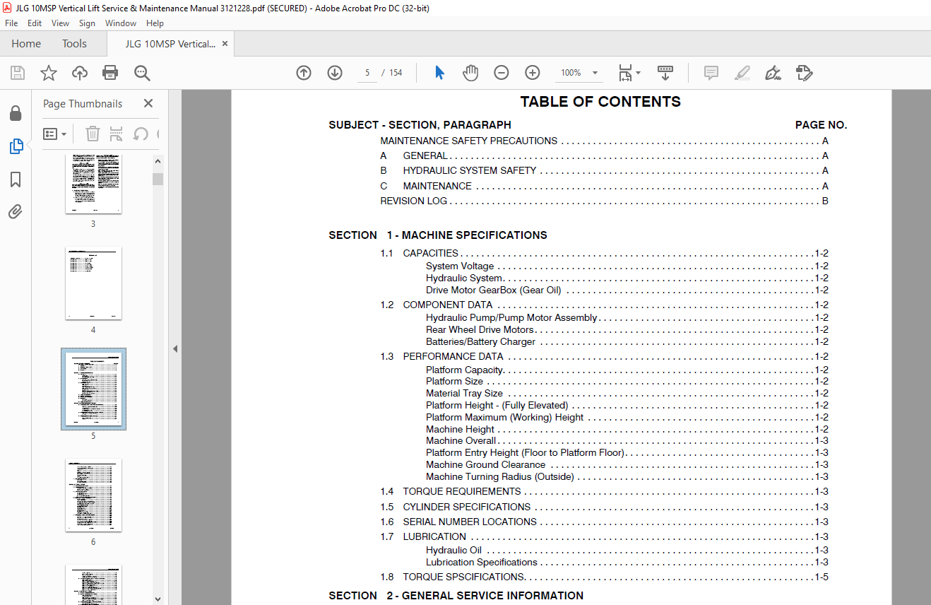

TABLE OF CONTENTS:
JLG 10MSP Vertical Lift Service & Maintenance Manual 3121228 – PDF DOWNLOAD
Maintenance safety precautions…………………………………………………….. 3
a. GENERAL…………………………………………………………………… 3
b. HYDRAULIC SYSTEM SAFETY…………………………………………………….. 3
c. MAINTENANCE……………………………………………………………….. 3
REVISION LOG…………………………………………………………………….. 4
TABLE OF CONTENTS………………………………………………………………… 5
Section 1. MACHINE specifications………………………………………………….. 13
1.1 Capacities……………………………………………………………….. 14
System Voltage……………………………………………………………. 14
Hydraulic System………………………………………………………….. 14
Drive Motor GearBox (Gear Oil)……………………………………………… 14
1.2 Component Data……………………………………………………………. 14
Hydraulic Pump/Pump Motor Assembly………………………………………….. 14
Rear Wheel Drive Motors……………………………………………………. 14
Batteries/Battery Charger………………………………………………….. 14
1.3 Performance Data………………………………………………………….. 14
Platform Capacity…………………………………………………………. 14
Maximum Horizontal Manual Side Force………………………………………… 14
Platform Size…………………………………………………………….. 14
Material Tray Size………………………………………………………… 14
Platform Height – (Fully Elevated)………………………………………….. 14
Platform Maximum (Working) Height…………………………………………… 14
Machine Height……………………………………………………………. 15
Machine Overall…………………………………………………………… 15
Platform Entry Height (Floor to Platform Floor)………………………………. 15
Machine Ground Clearance…………………………………………………… 15
Machine Turning Radius (Outside)……………………………………………. 15
1.4 Torque Requirements……………………………………………………….. 15
1.5 Cylinder Specifications……………………………………………………. 15
1.6 Serial Number Locations……………………………………………………. 15
1.7 Lubrication………………………………………………………………. 15
Hydraulic Oil…………………………………………………………….. 15
Lubrication Specifications…………………………………………………. 15
1.8 Torque SPEcifications……………………………………………………… 17
Section 2. GENERAL Service Information……………………………………………… 25
2.1 MACHINE PREPARATION, INSPECTION, AND MAINTENANCE……………………………… 25
General………………………………………………………………….. 25
Preparation, Inspection, and Maintenance…………………………………….. 25
Pre-Start Inspection………………………………………………………. 25
Pre-Delivery Inspection and Frequent Inspection………………………………. 25
Annual Machine Inspection………………………………………………….. 25
Preventative Maintenance…………………………………………………… 25
2.2 Preventive Maintenance and Inspection Schedule……………………………….. 26
Maintenance and Inspection Table Codes:……………………………………… 28
Footnotes:……………………………………………………………….. 28
2.3 Servicing and Maintenance Guidelines………………………………………… 29
General………………………………………………………………….. 29
Safety and Workmanship…………………………………………………….. 29
Cleanliness………………………………………………………………. 29
Components Removal and Installation…………………………………………. 29
Component Disassembly and Reassembly………………………………………… 29
Pressure-Fit Parts………………………………………………………… 29
Bearings…………………………………………………………………. 29
Gaskets………………………………………………………………….. 29
Bolt Usage and Torque Application…………………………………………… 30
Hydraulic Lines and Electrical Wiring……………………………………….. 30
Hydraulic System………………………………………………………….. 30
Lubrication and Servicing………………………………………………….. 30
Batteries………………………………………………………………… 30
Mast Chain Inspection Procedure…………………………………………….. 30
2.4 Lubrication Information……………………………………………………. 32
Hydraulic System………………………………………………………….. 32
Hydraulic Oil…………………………………………………………….. 32
Changing Hydraulic Oil…………………………………………………….. 32
Lubrication Specifications…………………………………………………. 32
Section 3. BASE COMPONENTS………………………………………………………… 33
3.1 Base Assembly Components…………………………………………………… 33
3.2 Base Frame Covers…………………………………………………………. 34
Carry Deck Support Frame – Installation……………………………………… 34
Rear Bumper Cover – Installation……………………………………………. 35
Drive Motor Cover – Installation……………………………………………. 35
3.3 Drive And Caster Wheels……………………………………………………. 36
Tire Wear and Damage………………………………………………………. 36
Wheel and Tire Replacement…………………………………………………. 36
Wheel Installation………………………………………………………… 36
(Front) Caster Wheel – Installation…………………………………………. 36
3.4 Drive/Elevation Cut-out switch Installation………………………………….. 37
3.5 Wheel Drive Assembly – Servicing……………………………………………. 37
Roll and Leak Testing……………………………………………………… 37
Oil Type and Capacity……………………………………………………… 37
Drive Motor Brush Wear – Warning Indication………………………………….. 38
Wheel Drive Assembly – Removal From Machine………………………………….. 38
Wheel Drive Disassembly – Main Components……………………………………. 40
Replacing Drive Motor Brushes………………………………………………. 41
Gear Box Main Disassembly………………………………………………….. 43
Input Carrier Disassembly………………………………………………….. 44
Hub – Disassembly…………………………………………………………. 45
Spindle Disassembly……………………………………………………….. 46
Spindle Sub-Assembly………………………………………………………. 47
Hub Sub-Assembly………………………………………………………….. 48
Input Carrier Sub-Assembly…………………………………………………. 49
Main Gear Box Sub-Assembly…………………………………………………. 50
Motor, Brake and Gear Box Assembly………………………………………….. 51
3.6 Pump-Motor Assembly – Service Procedure……………………………………… 52
General………………………………………………………………….. 52
Hydraulic Pressure Settings and Adjustment…………………………………… 52
Hydraulic Pressure Gauge Connection…………………………………………. 53
After Filter Pressure Check………………………………………………… 53
Pump-Motor Assembly – Remove/Install………………………………………… 54
Pump-Motor Assembly – Remove/Install………………………………………… 54
Motor Assembly – Remove/Install – Reference Marks…………………………….. 54
Motor/Brush Cover – Remove/Install………………………………………….. 55
Brush Carrier Assembly – Remove/Install……………………………………… 56
Brush Assembly – Remove/Install…………………………………………….. 56
Tank Remove/Install……………………………………………………….. 56
Filter Screen Remove/Install……………………………………………….. 57
Pump Remove/Install……………………………………………………….. 57
Pressure Adjust Valve Remove/Install………………………………………… 57
Pressure Check Valve – Remove/Install……………………………………….. 57
3.7 bATTEries and Battery Charger – Service Procedures……………………………. 58
Battery Condition Testing………………………………………………….. 58
Battery Replacement……………………………………………………….. 58
Battery – Installation (2-12V Batteries)…………………………………….. 58
Battery Installation – (4-6V Batteries) (OPTION)……………………………… 59
Battery Charge LED Indicator on Platform Control Console………………………. 60
Battery Low Voltage Warning Indicators………………………………………. 60
Battery Charger General Information…………………………………………. 61
Battery Charging Status Indicators………………………………………….. 61
Battery Charger Maintenance Information……………………………………… 62
Battery Charger Check/Change Charging Algorithm………………………………. 62
Battery Charger Removal/Installation………………………………………… 63
Section 4. CONTROL COMPONENTS……………………………………………………… 65
4.1 CONTROL Components Overview………………………………………………… 65
4.2 Control Components – Installation…………………………………………… 66
Ground Control Module……………………………………………………… 66
Traction Control Module……………………………………………………. 67
Platform Control Console Installation……………………………………….. 67
Platform Junction Box – Install/Remove………………………………………. 68
Junction Box to Ground Control Harness – Remove/Install……………………….. 68
Platform Interlock Switch Circuit…………………………………………… 69
4.3 Ground Control Module – Service Procedure……………………………………. 71
Cover Removal/Installation…………………………………………………. 72
Power Selector/EStop Switch Installation…………………………………….. 73
4.4 Ground Control Module – Programming…………………………………………. 74
General………………………………………………………………….. 74
Programming Levels………………………………………………………… 74
Activating Programming Mode………………………………………………… 74
Entering Password…………………………………………………………. 74
Programming Mode Selection…………………………………………………. 75
Selecting Programmable Item to Adjust……………………………………….. 75
Adjusting Programmable Setting……………………………………………… 75
Service Programming Mode – (Level-2)………………………………………… 76
Operator Programming Mode – (Level-3)……………………………………….. 76
4.5 Platform Control Console – Service Procedures………………………………… 79
General………………………………………………………………….. 79
Remove Platform Control Console…………………………………………….. 79
Display/Controller Module Electrical Connections……………………………… 80
Mounting Bracket – Install/Remove…………………………………………… 80
Rear Cover – Install/Remove………………………………………………… 80
Display/Controller Module – Install/Remove…………………………………… 81
Drive/Lift Mode Switch – Install/Remove……………………………………… 81
Horn Button Switch – Install/Remove…………………………………………. 81
Key Switch – Install/Remove………………………………………………… 81
E-Stop/ShutDown Switch – Install/Remove……………………………………… 82
Joystick Assembly – Install/Remove………………………………………….. 82
Section 5. MAST COMPONENTS………………………………………………………… 83
5.1 Mast Components Overview…………………………………………………… 83
5.2 Mast Cover – Install/Remove………………………………………………… 84
5.3 Platform Assembly – install/ remove…………………………………………. 84
5.4 Material Tray – Install/Remove……………………………………………… 85
5.5 Platform – 7 FT. HEIGHT Limit Switch – OPTION………………………………… 85
5.6 Hydraulic Line – Disconnect – Special Tool…………………………………… 86
Tool Use – In-Line Style Fittings…………………………………………… 86
Tool Use – Angled Style Fittings……………………………………………. 87
5.7 Mast Assembly Install/REmove……………………………………………….. 88
Mast Removal……………………………………………………………… 88
Mast Installation…………………………………………………………. 89
5.8 MAST DISASSEMBLY PROCEDURE…………………………………………………. 89
Mast Disassembly Procedure…………………………………………………. 89
Mast Section-4 – Removal (Platform Mount)……………………………………. 89
Mast Section-3 – Removal…………………………………………………… 90
Mast Section-2 – Removal…………………………………………………… 90
Mast Section-1 – Disassembly……………………………………………….. 91
5.9 Cylinder Disassembly………………………………………………………. 91
Lift Cylinder Component Inspection………………………………………….. 92
Cylinder Assembly…………………………………………………………. 92
5.10 Mast Assembly……………………………………………………………. 94
Mast Section 1 – Assembly………………………………………………….. 95
Mast Section 2 – Assembly………………………………………………….. 95
Mast Section 3 – Assembly………………………………………………….. 98
Mast Section 4 – Assembly…………………………………………………..100
5.11 MAST CHAINS AND SEQUENCING CABLES ADJUSTMENT…………………………………103
Mast Chain/Cable Adjustment…………………………………………………103
Sequencing Cable Adjustment…………………………………………………103
SECTION 6. TROUBLESHOOTING…………………………………………………………105
6.1 General…………………………………………………………………..105
6.2 Troubleshooting Information…………………………………………………105
6.3 Hydraulic Circuit Checks (See Figure 6-8.)……………………………………105
6.4 ELECTRICAL CIRCUIT CHECKS…………………………………………………..105
General…………………………………………………………………..105
6.5 MULTIMETER BASICS………………………………………………………….106
Grounding…………………………………………………………………106
Backprobing……………………………………………………………….106
Min/Max…………………………………………………………………..106
Polarity………………………………………………………………….106
Scale…………………………………………………………………….106
Continuity Measurement Over Long Distances……………………………………109
Requirements:……………………………………………………………..109
Procedure…………………………………………………………………109
6.6 ELECTRICAL SWITCH TESTING…………………………………………………..110
Basic Check……………………………………………………………….110
Limit Switches…………………………………………………………….110
Automatic Switches…………………………………………………………111
Switch Wiring – Low Side, High Side………………………………………….111
6.7 Ground Control Module LCD Display……………………………………………112
6.8 TROUBLESHOOTING TABLES Index………………………………………………..118
SPECIFICATIONS FOR VARIOUS COMPONENTS PAGE……………………………………118
SPECIAL PIN EXTRACTOR TOOLS FOR ELECTRICAL CONNECTORS………………………….118
FAULT CODE TROUBLESHOOTING TABLES……………………………………………118
MAIN POWER CIRCUIT TROUBLESHOOTING…………………………………………..119
MAST TROUBLESHOOTING……………………………………………………….119
HYDRAULIC LEAK TROUBLESHOOTING………………………………………………119
BASE FRAME COMPONENTS TROUBLESHOOTING………………………………………..119
DRIVE SYSTEM TROUBLESHOOTING………………………………………………..119
6.9 SPECIFICATIONS FOR VARIOUS COMPONENTS………………………………………..120
6.10 SPECIAL PIN EXTRACTOR TOOLS FOR ELECTRICAL CONNECTORS…………………………120
6.11 FAULT CODE TROUBLESHOOTING TABLES…………………………………………..121
Machine in Drive Speed Cut-Back (Turtle) Mode All The Time……………………..121
Code 01 – Low Battery Voltage……………………………………………….122
Code 02 – RESERVED…………………………………………………………122
Code 03 – RESERVED…………………………………………………………122
Code 04 – Tilt Condition……………………………………………………123
Code 05 – RESERVED…………………………………………………………123
Code 06 – Drive Motor Brush Wear Warning Indicator…………………………….123
Code 07- Left Drive Motor – Disconnected……………………………………..123
Code 08 – Right Drive Motor – Disconnected……………………………………124
Code 09 – Left Brake – Disconnected………………………………………….124
Code 10 – Right Brake – Disconnected…………………………………………124
Code 11 – Left Drive Motor – Short Circuit……………………………………125
Code 12 – Right Drive Motor – Short Circuit…………………………………..125
Code 13 – Traction Module – In Fold Back……………………………………..125
Code 14 – Pump Motor – Disconnected………………………………………….126
Code 15 – Lift Down Valve – Disconnected……………………………………..126
Code 16 – Lift Down Valve – Short Circuit…………………………………….127
Code 17 – Ground Control Module – In Fold Back………………………………..127
Code 18 – Alarm – Short Circuit……………………………………………..128
Code 19 – Alarm – Disconnected………………………………………………128
Code 20 – Beacon – Short Circuit…………………………………………….128
Code 21 – Beacon – Disconnected……………………………………………..129
Code 22 – Horn – Short Circuit………………………………………………129
Code 23 – Horn – Disconnected……………………………………………….130
Code 24 – P1-Auxiliary #1 Circuit – Short Circuit……………………………..130
Code 25 – P1-Auxiliary #1 Circuit – Disconnected………………………………131
Code 26 – P1-Auxiliary #2 – Short Circuit…………………………………….131
Code 27 – P1-Auxiliary #2 – Disconnected……………………………………..132
Code 28 – RESERVED…………………………………………………………132
Code 29 – RESERVED…………………………………………………………132
Code 30 – Traction Module – No Communication with Ground Control Module………….133
Code 31 – Platform Control Console – No Communication with Ground Control Module….134
Code 32 – Pump Motor – Over Current………………………………………….134
Code 33 – RESERVED…………………………………………………………135
Code 34 – P2-Auxiliary #1 – Inhibit………………………………………….135
Code 35 – P2-Auxiliary #1 – Tie Down…………………………………………135
Code 36 – RESERVED…………………………………………………………135
Code 37 – RESERVED…………………………………………………………135
Code 38 – Battery Voltage Low – Warning Level 2 – Two (2) LED/LCDs lit…………..136
Code 39 – Battery Voltage Low – Warning Level 3 – One (1) LED/LCDs lit…………..136
Code 40 – RESERVED…………………………………………………………136
Codes 41 thru 46 – RESERVED…………………………………………………136
Codes (100 – 199) Ground Control Module – Fault Condition………………………136
Codes (200 – 299) Platform Control Console – Fault Condition……………………137
Codes (300 – 399) Traction Control Module – Fault Condition…………………….138
6.12 MAIN POWER CIRCUIT TROUBLESHOOTING………………………………………….139
Machine Will Not Power Up…………………………………………………..139
6.13 MAST TROUBLESHOOTING………………………………………………………140
Platform Will Not Lower Manually…………………………………………….140
Platform Lift Up And Down Jerky……………………………………………..140
Mast Noisy When Lifting And Lowering…………………………………………141
Platform (Mast) Won’t Stay Elevated………………………………………….142
Platform (Mast) Descends Too Slowly………………………………………….142
6.14 HYDRAULIC LEAK TROUBLESHOOTING……………………………………………..143
Miscellaneous Hydraulic Leak Troubleshooting………………………………….143
6.15 BASE FRAME COMPONENTS TROUBLESHOOTING……………………………………….144
Caster Wheels Not Operating Freely…………………………………………..144
6.16 DRIVE SYSTEM TROUBLESHOOTING……………………………………………….145
Won’t Climb Grade………………………………………………………….145
Machine Drives in Opposite Direction…………………………………………146
Machine Won’t Drive Straight………………………………………………..147
Noise From Drive Assembly…………………………………………………..148
VIDEO PREVIEW OF THE MANUAL:
PLEASE NOTE:
- This is the same manual used by the dealers to diagnose and troubleshoot your vehicle
- You will be directed to the download page as soon as the purchase is completed. The whole payment and downloading process will take anywhere between 2-5 minutes
- Need any other service / repair / parts manual, please feel free to contact [email protected] . We still have 50,000 manuals unlisted
S.M


