

JCB 520, 525 Loadall Service Manual – 9803/3620-9
APPLICABLE MODELS :
This Service Manual covers the following machines:
JCB Loadall 520-50 (520 N. Am.) – from Machine Serial Number 754001
JCB Loadall 525-50 – from Machine Serial Number 789308
JCB Loadall 525-50S – from Machine Serial Number 1037581
FILE DETAILS:
JCB 520, 525 Loadall Service Manual – 9803/3620-9
File Format : PDF
Language : English
Printable : Yes
Searchable : Yes
Bookmarked : Yes
P/N : 9803/3620 Issue 9
Total Pages : 280
DESCRIPTION:
JCB 520, 525 Loadall Service Manual – 9803/3620-9
GENERAL:
This Service Manual is designed for the benefit of JCB Distributor Service Engineers who are receiving or have received, training by JCB Technical Training Department. These personnel have a sound knowledge of safe workshop practices, safety procedures, and general techniques associated with the maintenance and repair of hydraulic earthmoving equipment. The replacement of oil seals, gaskets and any other components showing obvious signs of wear or damage is expected as a matter of course. Components should be cleaned and lubricated where appropriate, and any open hose or pipe connection must be blanked off to prevent the loss of hydraulic fluid or allow an ingress of dirt. Finally, please remember SAFETY COMES FIRST!
Service Manual Layout:
This Service manual is compiled in sections, the first three are numbered and contain information as follows:
1 General Information
2 Care and Safety
3 Routine maintenance
The remaining sections are alphabetically coded and deal with the overhaul and inspection of specific components, for example:
A Attachments
B Body and Framework ….etc.
- The page numbering in each alphabetically coded section is not continuous. This allows for the insertion of new information in later issues of this Service Manual. Section contents, technical data, circuit descriptions, operation descriptions etc are inserted, where necessary, at the beginning of each alphabetically coded section.
- Read the section contents to locate machine types, machine type identification is not listed on individual pages. All sections are listed on the front cover; tabbed divider cards align directly with each individual section for quick reference.
TABLE OF CONTENTS:
JCB 520, 525 Loadall Service Manual – 9803/3620-9
General Information
Identification
Torque Settings
Service Tools
Numerical List
Section C
Section E
Section F
Section H
Section K
Sealing and Retaining Compounds
Care and Safety
Safety Notices
General Safety
Operating Safety
Maintenance Safety
Lubricants – Health and Safety
Routine Maintenance
Lubricants and Capacities
520-50, 525-50 & 525-50S Machines (All Engine Builds)
Machine Safety
Working with the Boom Raised
Service Schedules
Grease
50 Hours
500 Hours
1000 Hours
Oiling
Boom Wear Pads
Tyres and Wheels
Engine Air Filter
Cleaning the Pre-Cleaner
Changing the Outer Element
Changing the Inner Element
Engine Oil and Filter
Checking the Oil level (A Series Engines)
Changing the Oil and Filter (A Series Engines)
Checking the Oil Level (R Series Engines)
Changing the Oil and Filter (R Series Engiens)
Engine Cooling System
Checking the Coolant Level
Coolant Mixtures
Changing the Coolant
Cab Heater Filter
Fuel System
Fuel Types
Filling the Tank
Cleaning the Lift Pump Gauze (Early Machines with Series A Engines)
Cleaning the Lift Pump Filter (Later Machines with series A Engines)
Draining the Filter (Series A Engines)
Changing the Filter Element (Series A Engines)
Draining the Filter (R Series Engine)
Changing the Filter Element (R Series Engine)
Draining the Sediment Bowl
Cleaning the Sediment Bowl
Priming the System
Machines with A series engines
Machines with Type RE engines
Transmission
Checking the Oil Level
Changing the Oil and Filter
Axles
Checking the Axle Oil Level
Changing the Axle Oil
Front and Rear Hub
Checking/Filling the Hub Oil Levels
Oil Immersed Brakes
Changing the Hub Oil
Hydraulic System
Checking the Fluid Level
Changing the Filter Element
Changing the Hydraulic Tank Filler Cap
Hose Burst Protection Valves
Checking the Hose Burst Protection Valves
Battery
Checking the Electrolyte Level
Body and Framework
Cab
Removal and Replacement
Direct Glazing
Tanks
Hydraulic Tank Removal and Replacement
Fuel Tank Removal and Replacement
Boom
Wear Pads – Removal and Replacement
Inner and Outer – Removal and Replacement
Adjusting Shovel Alignment
Electrics
Technical Data
Relay Identification
Fuse Identification
Test Methods
Use of Multimeter
Measuring DC Voltage
Measuring Resistance
Measuring Continuity
How to Test a Diode or a Diode Wire
Schematics
Machines with Permanent All-wheel Steer
Machines with 3-mode Steer Option
Machines with Type R Engine Build
Description
Wire Harness Numbers
Wire Number Identification
Batteries
Safety
Maintenance
Specific Gravity Test
High Rate Discharge Test
Alternator
Service Precautions
Charging Test
Removal and Replacement
Dismantling and Assembling
Starter Motor
Starting Circuit Test
Removal and Replacement
Dismantling and Assembling
Safe Load Indicator
Introduction
Adjustment
Fault Finding
Testing – SLI and LMI
Transducer Removal and Replacement
Hydraulics
Technical Data
Schematic Circuit
Machines with Permanent All-wheel steer
Machines with 3-Mode Steer Option
Fault Finding
Contents
Introduction to Hydraulic Symbols
Probable Causes – Action
Pump
Main Pump Removal and Replacement
Main Pump Dismantling, Inspecting and Assembling
Main Pump Testing
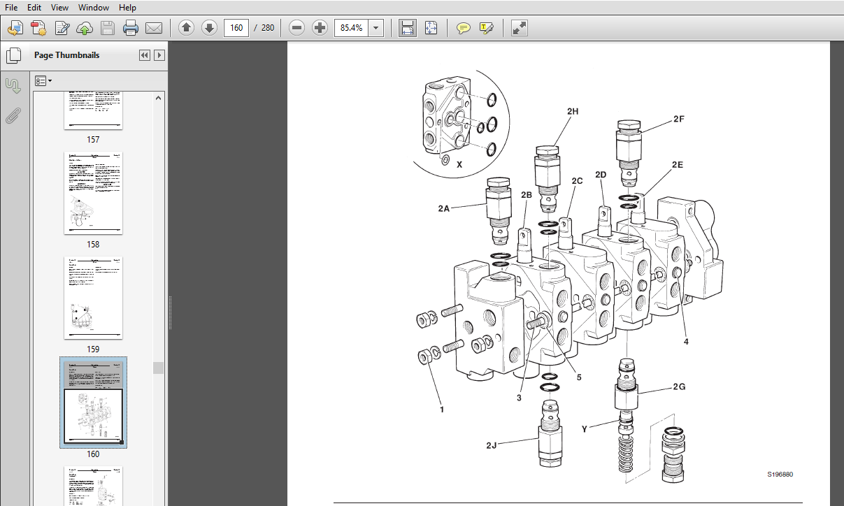
Valves
Valve Block Removal and Replacement
Valve Block Dismantle and Assembly
Main Relief Valve (MRV) Testing
Auxiliary Relief Valve (ARV) Testing
Rams
Lift Ram – Removal and Replacement
Displacement Ram -Removal and Replacement
Extension Ram – Removal and Replacement
Tilt Ram – Removal and Replacement
Typical Ram – Dismantle and Assembly
Transmission
Technical Data
Towing Procedure
Fault Finding
Syncro Shuttle Gearbox – Hydraulic
Syncro Shuttle Gearbox – Mechanical
Parking Brake
Torque Converter
Removal and Replacement
Syncro Shuttle
Removal and Replacement
Dismantling
Assembly
Reverser Unit
Dismantling
Assembly
Forward/Reverse Selector Valves
Syncro Shuttle
Pressure and Flow Testing
Torque Converter Stall Test
Front Axle
Removing and Replacing
Rear Axle
Removing and Replacing
Front and Rear Axles
Drive Head Dismantling and Assembly – SD40 & SD55
Drive Head with Limited Slip Differential – SD40
Dismantling
Assembly
Drive Head with Limited Slip Differential – SD55
Dismantling
Assembly
Crown Wheel and Pinion Adjustment
Renewing the Pinion Oil Seal
SD40 Axle Hub and Driveshaft
Dismantling
Assembly
SD55 Axle Hub and Driveshaft
Dismantling
Assembly
Propshafts
Removing and Replacing
Salvage/Repair
Drive Shaft Oil Seal
Oil Seal Replacement
Wear Sleeve Fitting
Axle and Gearbox Driveshaft Flange Seals
Hub and Driveshaft – Fitting Bearing Carrier Seal
Brakes
Technical Data
Descriptions
Charge/Priority Valve
Parking Brake
Testing
Dismantling and Assembly
Brake System
Brake Venting System
Residual Brake System Pressure
Bleeding Procedure
Dismantling and Assembly
Brake System Pressure Testing
Brake Seal and Component Leakage
Foot Brake Valve
Removal and Replacement
Dismantling and Assembly
Charge/Priority Valve
Pressure Testing
Removal and Replacement
Dismantling and Assembly
Steering
Technical Data
Circuit description
Service Procedures
Steer Mode Valve
Valves
Hydraulic Steering Unit, Dismantling and Assembling
Bleeding Procedure
Engine
Technical Data
Standard Procedures
Engine Speed Setting
Radiator Fan Speed setting
VIDEO PREVIEW OF THE MANUAL:

IMAGES PREVIEW OF THE MANUAL:

PLEASE NOTE:
- This is not a physical manual but a digital manual – meaning no physical copy will be couriered to you. The manual can be yours in the next 2 mins as once you make the payment, you will be directed to the download page IMMEDIATELY.
- This is the same manual used by the dealers inorder to diagnose your vehicle of its faults.
- Require some other service manual or have any queries: please WRITE to us at [email protected]


