

Isuzu N Series Engine Training Manual Download
FILE DETAILS:
Isuzu N Series Engine Training Manual Download
LANGUAGE:ENGLISH
PAGES:1640
DOWNLOADABLE:YES
FILE TYPE:PDF
VIDEO PREVIEW OF THE MANUAL:

IMAGES PREVIEW OF THE MANUAL:

SAMPLE PAGE FROM THE MANUAL:
Isuzu N Series Engine Training Manual Download
1. Attach the hydro boost and the master cylinder to the vehicle and connect the piping.
2. Fill the hydro boost reservoir with hydraulic oil between its minimum and maximum range.
3. Turn the engine on for about 5 seconds.
4. Then turn the engine off and check the quantity of hydraulic oil in the reservoir.
5. If the hydraulic oil is below the minimum, pour in more hydraulic oil so that it is in the range from minimum to maximum.
6. Repeat the above steps 2 — 5 until there is no foaming or change in the level of the hydraulic oil in the reservoir. But if the hydraulic oil foams during the above steps, let it stand for a while, wait for the foam to dissipate, then continue the work.
7. With the engine on, repeatedly press the brake pedal slowly about five times.
8. Then turn the engine off and check the quantity of hydraulic oil in the reservoir. If the hydraulic oil is below the minimum, once again pour in more hydraulic oil so that it is in the range from minimum to maximum.
9. Leaving the engine off, repeatedly press the brake pedal at least ten times.
10. Verify that there is no foam or change in the level of the hydraulic oil in the reservoir. If any foam remains, let it stand for a while, wait for the foam to dissipate, then repeat the above steps 7 — 9.
11. If it is necessary at this time to bleed out the air from the brake fluid pressure system, such as the master cylinder or the wheel cylinder, be sure to first complete step 10 above and make sure that the engine is on
TABLE OF CONTENTS:
Isuzu N Series Engine Training Manual Download
GENERAL INFORMATION
GENERAL INFORMATION 3
General Repair Instructions 3
General Repair Instructions 3
Identification 4
Chassis Number: 4
Engine Number: 4
Vehicle Identification Plate 4
Lifting Instruction 5
Lifting Instruction 5
Garage Jack and Safety Stand 5
Torque Specifications 8
Standard Bolts 8
Recommended Liquid Gasket 9
Recommended Liquid Gasket 9
Application Procedure 10
Recommended Thread Locking Agent 11
MAINTENANCE AND LUBRICATION 12
Maintenance Schedule 12
Recommended Fluids, Lubricants and Diesel Fuels 22
Recommended Fluids, Lubricants and Diesel Fuels 22
Oil Viscosity Chart 25
Engine Oil 25
Manual Transmission and Transfer Case Oil (Engine Oil) 26
Front Axle and Rear Axle Oil 27
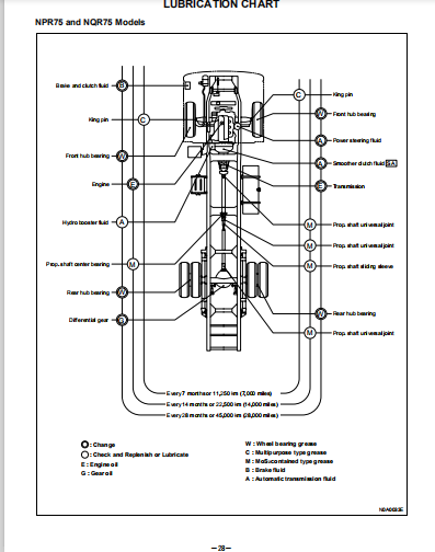
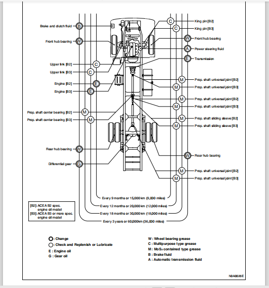
Lubrication Chart 28
NPR75 And NQR75 Models 28
NKR77 And NPR77 (Front Rigid Suspension) Models 29
NKR77 (Front Independent Suspension) Model 30
BRAKES
SERVICE INFORMATION 37
Troubleshooting 37
Brake System 37
Hydraulic Booster 42
Brake Lining 45
Brake Drum 46
Exhaust Brake 46
Parking Brakes 47
Main Data and Specifications 48
Service Standard 73
Servicing 74
Service Brakes 74
Parking Brake 80
Fixing Torque 82
Special Tools 92
Hydraulic Brakes 92
Anti-lock Brake System (ABS) 92
Parking Brakes 92
HYDRAULIC BRAKES 94
General Description 94
Hydraulic Brake System 94
Hydraulic Booster Brake System 95
Front Drum Brake 97
Front Drum Brake (Auto-adjuster Type) 98
Rear Drum Brake (Manual Adjuster Type) 99
Rear Drum Brake (Auto-adjuster Type) 100
Auto-adjuster 102
Operation Of Auto-adjuster 107
Front Disc Brake 108
Load Sensing Proportioning Valve (LSPV) 109
Deceleration Sensing Proportioning Valve (DSPV) 109
On-vehicle Service 110
Front Disc Brake Assembly 110
Front Disc Brake Pad 116
Front Drum Brake Assembly (Two Leading and Dual Two Leading) 122
Rear Drum Brake Assembly (Except Drum Inside Diameter 370 Mm) 130
Rear Drum Brake Assembly (Drum Inside Diameter 370 Mm) 138
Brake Pedal and Control 142
Hydraulic Booster And Brake Pedal Assembly 149
Hydraulic Booster 152
Accumulator and O-ring Replacement 154
Clevis and Lock Nut Replacement 155
Guard Replacement 156
Load Sensing Proportioning Valve 157
Deceleration Sensing Proportioning Valve 161
Unit Repair 163
Wheel Cylinder Assembly (Without Auto-adjuster) 163
Wheel Cylinder Assembly (With Auto-adjuster) 166
Master Cylinder Assembly (NHR) 180
Master Cylinder Assembly (NKR / NPR / NQR / NPS) 183
ANTI-LOCK BRAKE SYSTEM (ABS) 187
General Description 187
Service Precaution 187
General Description 187
System Components 188
Electronic Hydraulic Control Unit (EHCU) 188
Hydraulic Unit (HU) 188
ABS Warning Light 188
Wheel Speed Sensor 188
Normal and Anti-lock Braking 188
Brake Pedal Travel 189
Acronyms and Abbreviations 189
General Diagnosis 190
General Information 190
ABS Service Precautions 190
Computer System Service Precautions 190
General Service Precautions 190
Note On Intermittents 190
Test Driving ABS Complaint Vehicles 190
“ABS” Warning Light 191
Normal Operation 191
Basic Diagnostic Flow Chart 191
Basic Inspection Procedure 192
Tech 2 Scan Tool 193
Tech 2 Features 194
Getting Started 194
Operating Procedure (For Example) 195
DTC Modes 196
DTC Information Mode 196
Plotting Snapshot Graph 197
Plotting Graph Flow Chart (Plotting Graph After Obtaining Vehicle Information) 198
Flow Chart for Snapshot Replay (Plotting Graph) 199
Tech 2 Data Display 200
Special Function 200
EHCU Connector Pin-out Checks 204
Parts Location 205
Circuit Diagram 207
Connector List 213
Symptom Diagnosis 218
Symptom Diagnosis 218
Chart A-1 ABS Works Frequently But Vehicle Does not Decelerate 218
Chart TA-1 ABS Works Frequently But Vehicle Does not Decelerate (Use Tech 2) 219
Chart A-2 Uneven Braking Occurs While ABS Works 219
Chart TA-2 Uneven Braking Occurs While ABS Works (Use Tech 2) 220
Chart A-3, TA-3 The Wheels Are Locked 220
Chart A-4, TA-4 Braking Sound (From Hydraulic Unit) Is Heard While Not Braking 221
Diagnostic Trouble Codes 222
Diagnostic Trouble Codes 222
Diagnosis By “ABS” Warning Light Illumination Pattern 223
Diagnosis By “ABS” Warning Light Illumination Pattern 223
Diagnostic Trouble Codes (DTCs) 224
Chart B-1-1 With The Key In The ON Position (Before Starting The Engine)
Warning Light (W/l) Is not Activated 227
Chart 1 (DTC13/C0213) Vehicle Type Error 228
Chart 2 (DTC14/C0214) EHCU Abnormality 228
Chart 3 (DTC15/C0215) EHCU Voltage Out of Range 229
Chart 4 (DTC25/C0225) Exhaust Brake Cut Circuit Abnormality 230
Chart 5 (DTC33/C0233) Motor Drive Circuit Abnormality 230
Chart 6 (DTC 34/C0234) Abnormal Motor Rotation 230
Chart 7 (DTC41/C0241) Solenoid Valve Power Supply Abnormality 231
Chart 8 (DTC 43, 45/C0243, C0245) Solenoid Valve Circuit Abnormality 231
Chart 9 (DTC51/C0251) FL Speed Sensor Circuit Abnormality 231
Chart 10 (DTC52/C0252) FR Speed Sensor Circuit Abnormality 231
Chart 11 (DTC53/C0253) RL Speed Sensor Circuit Abnormality 232
Chart 12 (DTC54/C0254) RR Speed Sensor Circuit Abnormality 233
Chart 13 (DTC61/C0261) Abnormal FL Speed Sensor Signal 234
Chart 14 (DTC62/C0262) Abnormal FR Speed Sensor Signal 235
Chart 15 (DTC63/C0263) Abnormal RL Speed Sensor Signal 237
Chart 16 (DTC64/C0264) Abnormal RR Speed Sensor Signal 238
Unit Inspection Procedure 240
Unit Inspection Procedure 240
Chart C-1-1 FL Speed Sensor Output Inspection Procedure 240
Chart C-1-2 FR Speed Sensor Output Inspection Procedure 241
Chart C-1-3 RL Speed Sensor Output Inspection Procedure 241
Chart C-1-4 RR Speed Sensor Output Inspection Procedure 243
Chart TC-1 Sensor Output Inspection Procedure (Use Tech 2) 244
On-vehicle Service 245
Electronic Hydraulic Control Unit (EHCU) 245
Front Speed Sensor 248
Front Speed Sensor Rotor 249
Rear Speed Sensor 251
Rear Speed Sensor Rotor 253
PARKING BRAKES 255
General Description 255
Parking Brake Assembly, Parking Brake Lever 256
Unit Repair [178 mm, 190 mm TYPE] 261
Unit Repair [203 mm TYPE] 264
EXHAUST BRAKE 267
General Description 267
On-vehicle Service 268
Unit Repair 270
ABS/ASR
ABS/ASR 279
ABS/ASR System 279
Description of Function and Operation 279
Parts Location 287
Circuit Diagram 289
Connector List 290
Procedure of Trouble Diagnosis 292
Function Check 297
Trouble Diagnosis with Scan Tool 301
List of Diagnostic Trouble Code 308
ABS Warning Lamp does not Come on with the Starter Switch ON 312
ABS Warning Lamp Repeats Blinking After Turning the Starter Switch to ON 313
ABS Warning Lamp Repeats Blinking After Turning the Starter Switch to ON 314
DTC:C0213 (Flash Code 13) Model Type Identification Fault Due to Wrong Assembly of
Control Unit 315
DTC:C0214 (Flash Code 14) EHCU Fault5A4-40 317
DTC:C0215 (Flash Code 15) ECU Power Supply Fault 318
DTC:C0216 (Flash Code 16) CAN Communication Fault 319
DTC:C0226 (Flash Code 26) ECM Communication Fault 321
DTC:C0233 (Flash Code 33) Motor Drive Circuit Fault 322
DTC:C0234 (Flash Code 34) Motor Rotation Fault 323
DTC:C0235 (Flash Code 35) ASR Communication Line Fault/ASR Continuous Operation 324
DTC:C0241 (Flash Code 41) Fail-Safe Relay Fault 325
DTC:C0243 (Flash Code 43) Solenoid Drive Circuit Fault 326
DTC:C0245 (Flash Code 45) Solenoid Monitor Circuit Fault 327
DTC:C0251 (Flash Code 51) Speed Sensor Open/ Short Circuit; FL 328
DTC:C0252 (Flash Code 52) Speed Sensor Open/ Short Circuit; FR 329
DTC:C0253 (Flash Code 53) Speed Sensor Open/ Short Circuit; RL 330
DTC:C0254 (Flash Code 54) Speed Sensor Open/ Short Circuit; RR 331
DTC:C0261 (Flash Code 61) Speed Sensor Signal Fault/Wrong Tire Size; FL 332
DTC:C0262 (Flash Code 62) Speed Sensor Signal Fault/Wrong Tire Size; FR 334
DTC:C0263 (Flash Code 63) Speed Sensor Signal Fault/Wrong Tire Size; RL 336
DTC:C0264 (Flash Code 64) Speed Sensor Signal Fault/Wrong Tire Size; RR 338
List of Trouble Symptom 339
Symptom: [The ABS Operates Frequently but Brake Force is Insufficient,
or the ASR Operates Frequently] (Check Flow A-1) 340
Symptom: [The ABS Operates Frequently but Brake Force is Insufficient,
or the ASR Operates Frequently] (Check Flow TA-1) 341
Symptom: [The ABS Operates but Pulling to One Side] (Check Flow A-2) 342
Symptom: [The ABS Operates but Pulling to One Side] (Check Flow TA-2) 343
Symptom: [Wheels are Locked During Brake Operation] (Check Flow A-3, TA-3) 344
Symptom: [Feeling of Brake Pedal is Faulty] (Check Flow A-4) 345
Symptom: [Brake Operating Noise Comes from the Hydraulic Unit Though the Brake
Pedal is not Depressed] (Check Flow A-5, TA-5) 346
Electronic Hydraulic Control Unit (EHCU) 347
Components 347
Removal 347
Installation 349
Speed Sensor (Front) 351
Components 351
Removal 351
Installation 351
Inspection 352
Sensor Rotor (Front Wheel) 355
Components 355
Removal 355
Installation 356
Sensor Harness (Rear Axle) 359
Components 359
Removal 359
Installation 359
Rear Speed Sensor 361
Components 361
Removal 361
Installation 363
Inspection 365
Rear Sensor Rotor 370
Components 370
Removal 370
Installation 371
ENGINE 4H SERIES
SERVICE INFORMATION 379
Troubleshooting 379
Hard Starting 379
Unstable Idling 385
Insufficient Power 386
Excessive Fuel Consumption 387
Excessive Oil Consumption 387
Overheating 387
White Exhaust Smoke 388
Dark Exhaust Smoke 388
Oil Pressure Does Not Rise 388
Abnormal Engine Noise 389
Engine Cooling Trouble 390
Starter Motor Does Not Stop 391
Main Data and Specifications 392
Main Data and Specifications 392
Service Standard 402
Engine 402
Cylinder Head 402
Camshaft 403
Rocker Arm and Rocker Arm Shaft 404
Valve 404
Cylinder Body 405
Crankshaft 407
Piston 408
Piston Pin 408
Piston Ring 409
Connecting Rod 409
Flywheel 410
Gear Train 411
Lubrication System 411
Cooling System 412
Fuel System 413
Engine Electrical 413
Servicing 416
Model Identification 416
Air Cleaner 416
Lubricating System 417
Fuel System 419
Cooling System 423
Engine Control 426
Accelerator Control 426
Engine Stop Control 427
Valve Clearance Adjustment 427
Injection Timing Adjustment 429
Compression Pressure Measurement 432
Quick-On-Start II System 432
Fixing Torque 433
Cylinder Head, Head Gasket and Head Cover 433
Crankshaft, Flywheel, Damper Pulley, Connecting Rod and Oil Pan 435
Gear Train, Camshaft, Rocker Arm Shaft, Front Retainer, Flywheel Housing 436
Inlet Cover and Exhaust Manifold 437
Turbocharger, Water Pipe and Oil Pipe 439
Water Pump, Water Outlet Pipe, Oil Pump, Oil Cooler and Oil Filter 440
Generator, Starter and Glow Plug 441
Engine Mounting 442
Injection Pump, Injection Pipe and Fuel Pipe 443
Special Tools 444
Special Tools 444
Lubricating System 446
General Description 446
ENGINE MECHANICAL 447
Cylinder Head 447
Component 447
Disassembly 447
Clean 448
Inspection and Repair 448
Reassembly 448
Valve Spring, Valve Guide Oil Seal, Valve, Valve Guide 453
Component 453
Disassembly 453
Inspection and Repair 454
Reassembly 459
Camshaft 461
Component 461
Disassembly 461
Inspection and Repair 462
Reassembly 463
Rocker Arm Assembly 464
Component 464
Disassembly 464
Inspection and Repair 465
Reassembly 467
Oil Pump 469
Component 469
Disassembly 469
Inspection and Repair 471
Reassembly 472
Crankshaft 476
Component 476
Disassembly 477
Inspection and Repair 481
Reassembly 491
Piston And Connecting Rod 500
Component 500
Disassembly 500
Inspection and Repair 502
Reassembly 506
Cylinder Block 510
Component 510
Disassembly 511
Inspection and Repair 515
Reassembly 520
ENGINE 535
General Description 535
Cylinder Head 537
Cylinder Block 537
Piston, Connecting Rod and Crankshaft 538
Valve Train 539
Fuel System 540
Intake and Exhaust Systems 540
Lubrication System 541
Cooling System 541
Important Operations 542
Engine Mount (RH,LH) 543
Component 543
Removal 543
Installation 544
Cylinder Head Cover 545
Component 545
Removal 545
Installation 545
Inlet Cover / Inlet Case 547
Component 547
Removal 547
Installation 549
Exhaust Gas Recirculation System (EGR) 553
Component 553
Removal 553
Installation 553
Exhaust Gas Recirculation System (EGR) 556
Component 556
Removal 556
Installation 556
Exhaust Manifold 588
Component 588
Removal 558
Installation 559
Timing Gear Replacement 561
Component 561
Removal 562
Inspection 566
Installation 567
Valve Guide Seal & Valve Spring 572
Component 572
Removal 572
Installation 574
Rocker Arm Shaft Assembly 577
Component 577
Removal 577
Installation 578
Camshaft Assembly 580
Component 580
Removal 580
Installation 581
Cylinder Head 583
Component 583
Removal 585
Installation 587
Circumference Parts Of Cylinder Head 593
Component 593
Removal 593
Installation 594
Oil Filter Assembly 599
Component 599
Removal 599
Inspection 599
Installation 599
Oil Filter Cartridge 601
Component 601
Removal 601
Installation 601
Oil Cooler 602
Component 602
Removal 603
Disassembly 605
Reassembly 605
Installation 606
Oil Pan 611
Component 611
Removal 611
Installation 611
Oil Pump Assembly 614
Component 614
Removal 615
Installation 616
Oil Relief Valve 619
Removal 619
Inspection and Repair 619
Installation 619
Piston, Piston Ring, Piston Pin And Connecting Rod 620
Component 620
Removal 620
Installation 622
Flywheel And Pilot Bearing 625
Component 625
Removal 625
Inspection and Repair 627
Installation 628
Crankshaft Front Oil Seal 630
Component 630
Removal 630
Installation 632
Crankshaft Rear Oil Seal 636
Component 636
Removal 636
Installation 637
Crankshaft 640
Component 640
Removal 641
Installation 646
Cylinder Block 654
Component 654
Removal 655
Installation 662
Engine Assembly 678
Component 678
Removal 682
Installation 684
ENGINE COOLING 691
General Description 691
Water Pump 692
Thermostat 692
Radiator 693
Anti-freeze Solution 693
Water Pump 695
Component 695
Removal 695
Inspection 696
Installation 696
Thermostat 698
Component 698
Removal 698
Inspection 698
Installation 699
Radiator 700
Component 700
Removal 700
Inspection 701
Installation 701
Drive Belt Adjustment 703
Component 703
Inspection 703
FUEL SYSTEM 705
General Description 705
Fuel Flow 706
Brief Explanation of Emission and Electrical Control System 708
Governor (Model RLD-M) 709
Injection Nozzle 710
Fuel Filter and Water Separator 711
Fuel Filter Assembly (Except 4HF1-2 Model) 712
Component 712
Removal 712
Installation 712
Cartridge Replacement 713
Fuel Filter Assembly (4HF1-2 Model Only) 715
Component 715
Removal 715
Installation 715
Cartridge Replacement 715
Injection Nozzle Assembly 717
Component 717
Removal 718
Disassembly 720
Reassembly 721
Disassembly 723
Reassembly and Opening Pressure Adjustment 724
Installation 733
Injection Pump Assembly (Except 4HF1-2 Model) 736
Component 736
Removal 736
Installation 739
Injection Pump Assembly (4HF1-2 Model Only) 743
Component 743
Installation 743
Injection Timing Adjustment 748
Injection Pump Notched Line Inspection 748
Injection Timing Adjustment (Except 4HF1-2 model) 748
Injection Timing Check (4HF1-2 model only) 749
Injection Timing Adjustment (4HF1-2 model only) 750
Idling Speed Adjustment (Except 4HF1-2 model) 751
Idling Speed Check & Adjustment (4HF1-2 model only) 751
Injection Pump Data 752
Injection Volume Adjustment (4HF1 Engine) 752
Injection Volume Adjustment (4HF1-2 Engine) 757
Injection Volume Adjustment (4HG1 Engine) 759
Injection Volume Adjustment (4HG1-T Engine) 762
Injection Volume Adjustment (4HE1-TC Engine) 765
Aneroid Compensator Adjustment 774
Component 774
Injection Volume Adjustment 775
4HE1-TC (4HE1-XS) Engine for EURO3 775
Fuel Tank 782
Component 782
Removal 782
Installation 782
Fuel Gauge Unit 784
Component 784
Removal 784
Installation 784
Accelerator Control Cable 785
Component 785
Removal 785
Inspection 785
Installation 785
Accelerator Pedal 787
Component 787
Removal 787
Installation 787
Idling Control Cable 788
Component 788
Removal 788
Installation 788
Air Cleaner Element 789
Component 789
Removal 789
Installation 790
ENGINE ELECTRICAL 791
Battery 791
General Description 791
Diagnosis 791
On-vehicle Service 792
Main Data and Specifications 793
STARTING SYSTEM 794
General Description 794
Component 794
On-vehicle Service 797
Component 797
Removal 797
Installation 798
Unit Repair 799
Component 799
Disassembly 801
Inspection and Repair 803
Reassembly 807
CHARGING SYSTEM 810
General Description 810
Component 810
Diagnosis 812
On-vehicle Service 813
Component 813
Removal 813
Installation 813
Unit Repair 816
Component 816
Disassembly 817
Inspection and Repair 818
Reassembly 824
Inspection 827
QOS II PREHEATING SYSTEM 830
General Description 830
Component 831
Starting Circuit Diagram (Reference) 832
Component 832
Inspection and Repair 833
Troubleshooting 836
EMISSION AND ELECTRICAL DIAGNOSIS 838
General Description 838
Notes for Working on Electrical Items 838
Symbols and Abbreviations 844
Connector Inspecting Procedure 846
Parts for Electrical Circuit 847
Diagnosis (4HE1-TC Only) 850
Strategy-based Diagnostics 850
General Service Information 851
On-Board Diagnostic (OBD) 851
Reading Diagnostic Trouble Codes Using a Tech 2 or Other Scan Tool 852
Typical Scan Data Values 856
Troubleshooting 856
Self-diagnosis Functions 858
Diagnosis Trouble Code List 860
Location of Sensor and Switch 862
Parts Location 864
Engine Control Module (ECM) 865
Chart of Engine Control Module (ECM) Input/Output 866
Location of the Engine Control Module (ECM) Connector 868
Location of Data Link Connector (DLC) 868
Brief Explanation Of Emission And Electrical Control System 870
MITICS (Mechanically Integrated Timing and Injection Control System) 870
Governor (Model RLD-M) 871
EGR (Exhaust Gas Recirculation) System 872
VSS (Variable Swirl System) 874
Engine Control Module (ECM) System Wiring Diagram 875
Auxiliary Engine Control System 876
Vacuum Switching Valve (VSV) Circuit 878
Exhaust Brake and Engine Warm-up Control 880
DTC-P13 Engine Coolant Temperature (ECT) Sensor Circuit High Voltage 881
DTC-P14 Engine Coolant Temperature (ECT) Sensor Circuit Low Voltage 885
DTC-P21 Rack Sensor Circuit Low Voltage 889
DTC-P22 Rack Sensor Circuit High Voltage 892
DTC-P23 Solenoid Switch Control Circuit Low Voltage 895
DTC-P24 Solenoid Switch Control Circuit High Voltage 899
DTC-P26 Quick Warm System (QWS) Relay Control Circuit High Voltage 903
DTC-P31 Exhaust Gas Recirculation (EGR) Electronic Vacuum Regulating Valve (EVRV)
Solenoid Control Low Voltage 907
DTC-P32 Exhaust Gas Recirculation (EGR) Electronic Vacuum Regulating Valve (EVRV)
Solenoid Control High Voltage 910
DTC-P33 Variable Swirl System (VSS) Control Circuit Low Voltage 913
DTC-P34 Variable Swirl System (VSS) Control Circuit High Voltage 917
DTC-P35 Exhaust Gas Recirculation (EGR) Quick Cut Vacuum Switching Valve (VSV)
Control Circuit Low Voltage 920
DTC-P36 Exhaust Gas Recirculation (EGR) Quick Cut Vacuum Switching Valve (VSV)
Control Circuit High Voltage 924
DTC-P41 Quick On Start (QOS) Relay Control Circuit Low Voltage 927
DTC-P42 Quick On Start (QOS) Relay Control Circuit High Voltage 931
DTC-P43 Aneroid Compensator Vacuum Switching Valve (VSV) Control Circuit Low Voltage 935
DTC-P44 Aneroid Compensator Vacuum Switching Valve (VSV) Control Circuit High Voltage 939
DTC-P45 Engine Speed Sensor Circuit Low Voltage 943
DTC-P52 Electronically Erasable Programmable Read Only Memory (EEPROM) Error 947
DTC-P61 Barometric Pressure Sensor Circuit Error 947
Without Diagnosis Trouble Code 948
Engine Hunting 949
Startup Failure 950
White Smoke (Excessive) 952
Black Smoke (Excessive) 954
Lack of Power 956
High Idle Engine Speed 958
Solenoid Switch Malfunction 959
Exhaust Brake Malfunction 960
EGR System Malfunction 965
Variable Swirl System (VSS) System Malfunction (Equipped with Exhaust gas recirculation
and VSS) 968
Aneroid Compensator Malfunction 972
Quick Warm System (QWS) Malfunction 975
Fast Idle Control Device (FICD) System Malfunction 980
Special Tools 983
Diagnosis (4HG1-T only) 985
Strategy-Based Diagnostics 985
General Service Information 986
Troubleshooting 987
Self-diagnosis Functions 987
Diagnosis Trouble Code (DTC) List 990
Location of Sensor and Switch 991
Parts Location 993
Engine Control Module (ECM) 994
Chart of Engine Control Module (ECM) Input/Output 995
Location of the Engine Control Module (ECM) Connector 996
Location of Data Link Connector (DLC) 996
Engine Control Module (ECM) System Wiring Diagram 998
Auxiliary Engine Control System (Equipped with Exhaust gas recirculation (EGR)) 999
Vacuum Switching Valve (VSV) Circuit (Equipped with Exhaust gas recirculation (EGR)) 1000
Exhaust Brake Control 1001
DTC-13 Engine Coolant Temperature (ECT) Sensor Circuit High Voltage 1002
DTC-14 Engine Coolant Temperature (ECT) Sensor Circuit Low Voltage 1005
DTC-21 Rack Sensor Circuit Low Voltage 1008
DTC-22 Rack Sensor Circuit High Voltage 1011
DTC-31 Exhaust Gas Recirculation (EGR) Vacuum Switching Valve (VSV)
Solenoid Control Low Voltage 1014
DTC-32 Exhaust Gas Recirculation (EGR) Vacuum Switching Valve (VSV)
Solenoid Control High Voltage 1017
DTC-41 Quick On Start (QOS) Relay Control Circuit Low Voltage 1020
DTC-42 Quick On Start (QOS) Relay Control Circuit High Voltage 1024
DTC-52 Electronically Erasable Programmable Read Only Memory (EEPROM) Error 1027
Without Diagnosis Trouble Code 1028
Startup Failure (Quick On Start (QOS) only) 1029
Black Smoke (Excessive) 1031
Lack of Power 1033
Exhaust Brake Malfunction (Exhaust Brake only) 1035
Exhaust Gas Recirculation (EGR) System Malfunction 1041
Special Tools 1044
EXHAUST 1045
General Description 1045
Component 1045
Gasket 1045
On-vehicle Service 1047
Component 1047
Removal 1047
Installation 1048
TURBOCHARGER 1049
General Description 1049
On-vehicle Service 1050
Charge Air Pipe 1050
Intake Manifold 1050
Turbocharger 1051
Inspection and Repair 1052
Exhaust Manifold 1055
Turbocharger Turbine Housing Replacement (For 4HG1-T Model) 1055
Charge Air Cooler 1059
MANUAL TRANSMISSION AND CLUTCH MYY SERIES
GENERAL INFORMATION 1067
General Repair Instructions 1067
General Precautions 1067
Lifting Points 1068
Lifting Points for Originally Equipped Jack 1068
Floor Jack Lifting Points and Chassis Stand Position 1069
Cab Tilting 1071
Notes for Tilting of the Cab 1071
Notes For Working On Electric Equipment 1072
Battery Cable 1072
Connector Handling 1072
Electric Equipment Handling 1074
Cable Harness 1075
Vehicles With SRS Airbag System 1077
Notes for Handling SRS Airbag System 1077
Notes For Electronic Control System Inspection And Service 1079
Scan Tool (External Diagnosis Device) 1079
Circuit Tester 1079
Failure due to Static Electricity Discharge 1079
Additional Electric Equipment 1079
Notes for Welding 1079
Repetition of Trouble 1079
Recommended Liquid Gasket And Loctite 1080
Liquid Gasket 1080
Recommended Loctite (Thread Locking Agent) 1081
Terms And Abbreviations 1082
Term Definition 1082
Abbreviations Charts 1082
Introduction of SI (International System of Unit) 1084
Standard Bolts Tightening 1085
Isuzu Standard Fixing Torque Specifications 1085
Isuzu Standard Bolt Head Marks 1088
Arrows Used In Figures 1089
Arrows Descriptions 1089
MANUAL TRANSMISSION 1090
Manual Transmission Mechanism 1090
Function and Operation 1090
Inspection 1091
On-vehicle Service 1095
Change Lever 1095
Gear Control Cable 1096
Vehicle Speed Sensor 1103
Reverse and Neutral Switch 1103
Rear Oil Seal (5MT) 1105
Rear Oil Seal (6MT) 1108
Transmission Assembly 1110
Unit Repair 1115
Transmission (5MT) 1115
Transmission (6MT) 1132
Top Gear Shaft 1151
Main Shaft (5MT) 1152
Main Shaft (6MT) 1163
Counter Shaft (5MT) 1173
Counter Shaft (6MT) 1177
Control Box 1181
Transfer System (MYY Rigid Type) 1186
Transfer Assembly (MYY Rigid Type) 1187
Transfer (MYY Rigid Type) 1189
CLUTCH 1201
General Description 1201
Clutch System 1201
On-vehicle Service 1205
Clutch Assembly 1205
Clutch Control 1211
Unit Repair 1214
Master Cylinder 1214
Clutch Booster 1216
Slave Cylinder 1219
CAB AND CHASSIS ELECTRICAL (LEFT HAND DRIVE MODEL)
CAB AND CHASSIS ELECTRICAL 1229
General Information 1229
General Information 1229
Notes for Working on Electrical Items 1229
Symbols and Abbreviations 1236
Parts for Electrical Circuit 1238
Reading The Circuit Diagram 1246
Main Data And Specifications 1249
Bulb Specifications 1249
Fuse and Fusible Link Location 1252
Reference Table of Fuse and Circuit Breaker 1263
Relay Location 1269
Diode Location 1275
Reference Table of Grounding Point 1276
Grounding Point Location 1276
Cable Harness Routing 1277
System Repair 1281
Start and Charging 1281
QOS (Quick On Start) II System (4HF1 and 4JB1 Engine Model) 1295
Exhaust Brake System 1301
Exhaust Brake System and Engine Control 1311
Engine Stop System 1353
Headlight, Fog Light, Rear Fog Light and Cornering Light 1360
Headlight Leveling 1386
Clearance Light, Taillight, License Plate Light and Illumination Light 1395
Turn Signal Light, Hazard Warning Light, and Stoplight 1410
Horn, Backup Light and Backup Buzzer 1424
Dome Light and Key Remind Buzzer 1436
Power Door Lock 1446
Power Window 1458
Windshield Wiper and Washer 1474
Audio and Cigar Lighter 1493
Meter and Warning/indicator Light 1501
Heater and Air Conditioning 1557
Fuel Heater and Rear Heater 1569
4WD Transfer (Vacuum Control) 1575
ABS (Anti-lock Brake System, Without ASR) 1581
ABS/ASR System 1590
Transmission Control System (Smoother) 1595
Electronic Control Type PTO 1613
PLEASE NOTE:
⦁ This is the SAME manual used by the dealers to troubleshoot any faults in your vehicle. This can be yours in 2 minutes after the payment is made.
⦁ Contact us at [email protected] should you have any queries before your purchase or that you need any other service / repair / parts operators manual.


