

Hyster E25 35XM, E40XMS service manual
File Details:
Hyster E25 35XM, E40XMS service manual
Language : English
Pages : 548
Size : 16.28 MB
Downloadable : Yes
Format : PDF
Video Preview:

Image Preview:
Description:
Hyster E25 35XM, E40XMS service manual
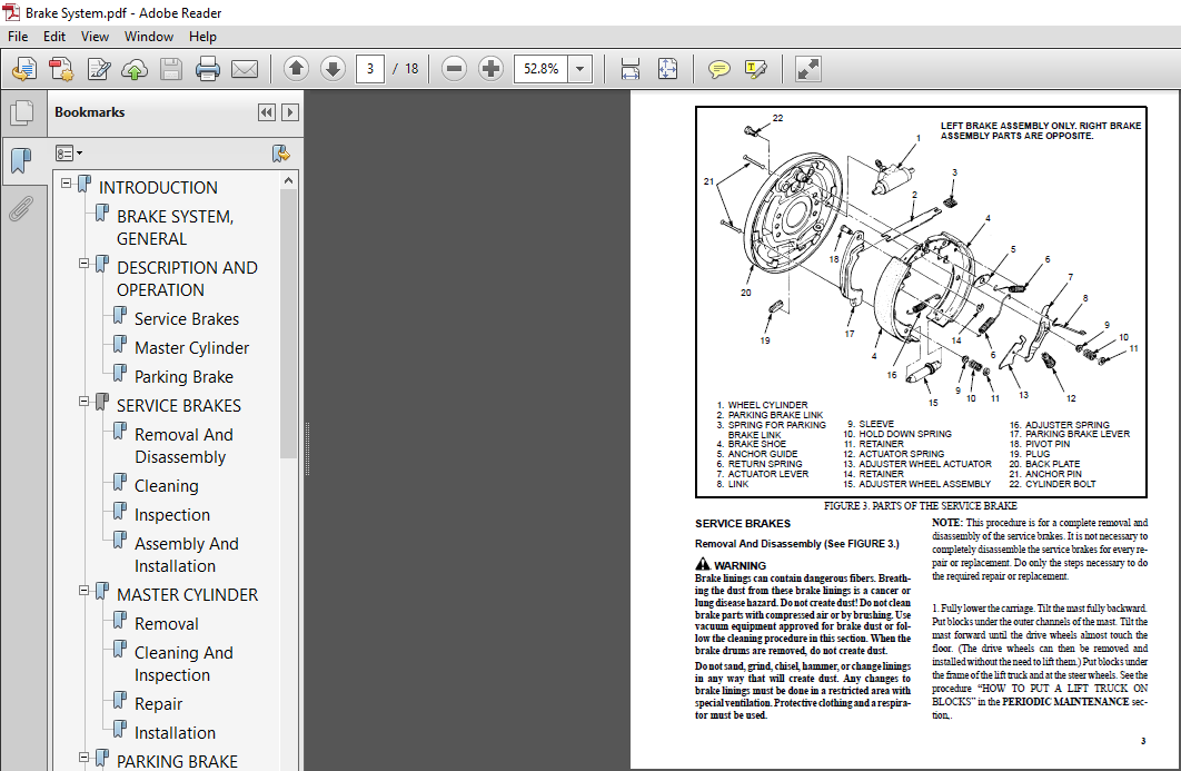
- BRAKE SYSTEM, GENERAL This section has a description and the service procedures for the brake systems. The service brake system includes the following parts: master cylinder, brake shoes, wheel cylinders, pedal and linkage. See FIGURE 1. The parking brake includes the pedal, linkage and cables to operate the service brake shoes. See FIGURE 9. Some units have an additional seat brake as shown in FIGURE 11. This seat brake is connected to the armature of the traction motor. DESCRIPTION AND OPERATION (See FIGURE 1. and FIGURE 2.) Service Brakes A service brake assembly is installed on the mounts at each end of the drive axle. The parts of the service brake assembly are shown in FIGURE 1. and FIGURE 3.
- When the brake pedal is pushed, fluid pressure from the master cylinder causes the pistons in the wheel cylinders to extend. The pistons push the brake shoes against the drums. FIGURE 1. SERVICE BRAKE SYSTEM 1. BRAKE PEDAL 2. MASTER CYLINDER 3. BRAKE ASSEMBLY 4. BRAKE FLUID RESERVOIR 12836 1 2 3 4 The clearance between the brake shoes and the hub is adjusted automatically. An adjuster linkage turns the adjuster wheel to adjust the clearance. When the lift truck moves in the REVERSE direction and the brakes are applied, the rear brake shoe and the adjuster links move with the drum. This linkage moves the adjuster lever to rotate the adjuster wheel. The adjuster wheel can turn only when there is clearance between the lining of the brake shoe and the hub. The adjuster wheel can also be turned with a tool. A slot in the back plate gives access to the adjuster wheel.
- Master Cylinder The master cylinder is designed for a dual circuit system. The master cylinder has two separate pistons that operate in the single bore of the master cylinder. The reservoir for the fluid is pressed into the two ports on top of the master cylinder and held in position by seals. When the brake pedal is pushed, the push rod moves the piston assemblies. The operation of the master cylinder is described in FIGURE
- 2. If a failure occurs in one of the dual circuits, the other circuit will apply one of the service brakes. This failure will cause the brake pedal to travel farther when the brakes are applied, but the service brakes on one drive wheel will operate. This failure of one of the brake circuits can cause the lift truck to turn toward the drive wheel with the good brake when the brakes are applied. The operator must control the direction of the lift truck with the steering when the brakes are applied during this condition. The reservoir is equipped with an indicator for low fluid level.
- A float in the reservoir moves up and down with the fluid level. When the fluid level is low, a magnet on the float activates a switch in the bottom of the reservoir. This switch energizes a warning light on the display panel. Parking Brake The parking brake system uses the service brake shoes. See FIGURE 5. Additional linkage activates the parking brake system. When the parking brake pedal is moved to apply the parking brake, the cables and linkage expand the brake shoes against the drum. The design of the parking brake linkage adjusts the tension in each cable so that the parking brake is applied evenly to the left and right brakes.
Table of Contents:
Hyster E25 35XM, E40XMS service manual
INTRODUCTION...............................................................................................................  1
	BRAKE SYSTEM, GENERAL..................................................................................................  1
	DESCRIPTION AND OPERATION..............................................................................................  1
		Service Brakes.....................................................................................................  1
		Master Cylinder....................................................................................................  1
		Parking Brake......................................................................................................  1
	SERVICE BRAKES.........................................................................................................  3
		Removal And Disassembly............................................................................................  3
		Cleaning...........................................................................................................  4
		Inspection.........................................................................................................  5
		Assembly And Installation..........................................................................................  5
	MASTER CYLINDER........................................................................................................  8
		Removal............................................................................................................  8
		Cleaning And Inspection............................................................................................  8
		Repair.............................................................................................................  8
		Installation.......................................................................................................  8
	PARKING BRAKE.......................................................................................................... 10
		Removal And Disassembly............................................................................................ 10
		Assembly And Installation.......................................................................................... 11
	REPLACE THE PARKING BRAKE SWITCH....................................................................................... 12
	CHECKS AND ADJUSTMENTS................................................................................................. 13
		Remove The Air From The Brake System............................................................................... 13
		Adjust The Service Brakes.......................................................................................... 13
		Adjust The Brake Pedal............................................................................................. 14
		Adjust The Master Cylinder......................................................................................... 14
		Adjust The Parking Brake........................................................................................... 14
		Adjust The Parking Brake Switch.................................................................................... 14
		Test The "Parking Brake Not Applied" Warning....................................................................... 14
		Adjust The Seat Brake.............................................................................................. 14
TORQUE SPECIFICATIONS...................................................................................................... 16
TROUBLESHOOTING............................................................................................................ 16
WHEELS AND TIRES .......................................................................................................... 19
COUNTERWEIGHTS............................................................................................................. 19
HYDRAULIC SYSTEM........................................................................................................... 19
CAPACITIES................................................................................................................. 19
BATTERY SPECIFICATIONS..................................................................................................... 20
BATTERY HEIGHT SPECIFICATIONS (Hoods and Battery Types).................................................................... 20
MAXIMUM CARRIAGE AND TILT CREEP RATES...................................................................................... 21
E25-40XM MAST SPEEDS (36 & 48 VOLT) Americas............................................................................... 21
	CONTACTOR CONTROLLED 184 mm (7.25 in) MOTOR & 19 cc (1.16 in3) LIFT PUMP*.............................................. 21
	TRAN. OR SCR CONTROLLED 184 mm (7.25 in) MOTOR & 19 cc (1.16 in3) LIFT PUMP*........................................... 22
	CONTACTOR CONTROLLED 184 mm (7.25 in) MOTOR & 12 cc (0.73 in3) LIFT PUMP............................................... 23
	CONTACTOR CONTROLLED 169 mm (6.65 in) MOTOR & 12 cc (0.73 in3) LIFT PUMP*.............................................. 24
E1.50-2.00XM MAST SPEEDS (48 VOLT) Europe.................................................................................. 25
	CONTACTOR CONTROLLED 184 mm MOTOR & 19 cc LIFT PUMP*................................................................... 25
	CONTACTOR CONTROLLED 169 mm MOTOR & 12 cc LIFT PUMP*................................................................... 26
	TRANSISTOR CONTROLLED 184 mm MOTOR & 19 cc LIFT PUMP*.................................................................. 27
	TRANSISTOR CONTROLLED 169 mm MOTOR & 12 cc LIFT PUMP*.................................................................. 28
E25-40XM, E25-40XM2 MAST SPEEDS (3/99) Americas............................................................................ 29
	184 mm (7.25 in) MOTOR & 19 cc (1.16 in3) LIFT PUMP*................................................................... 29
	184 mm (7.25 in) MOTOR & 12 cc (0.73 in3) LIFT PUMP*................................................................... 30
	169 mm (6.65 in) MOTOR & 12 cc (0.73 in3) LIFT PUMP*................................................................... 31
E1.50-1.75XM E2.00XMS MAST SPEEDS (3/99) Europe............................................................................ 32
	184 mm MOTOR & 19 cc LIFT PUMP*........................................................................................ 32
	169 mm MOTOR & 12 cc LIFT PUMP*........................................................................................ 33
TORQUE SPECIFICATIONS...................................................................................................... 33
REFERENCE TABLE............................................................................................................ 35
INTRODUCTION............................................................................................................... 36
	ELECTRIC MOTOR MAINTENANCE, GENERAL.................................................................................... 36
	BRUSH AND COMMUNICATOR INSPECTION...................................................................................... 36
		Hydraulic Pump Motor And Traction Motor............................................................................ 36
		Steering Pump Motor................................................................................................ 38
BRUSH WEAR REPLACEMENT GUIDE............................................................................................... 38
	Commutator Problems.................................................................................................... 40
	BRUSH REPLACEMENTS..................................................................................................... 42
	DISASSEMBLY OF MOTORS.................................................................................................. 44
		Traction Motor And Hydraulic Pump Motor............................................................................ 44
		Steering Pump Motor................................................................................................ 50
	ASSEMBLY OF MOTORS..................................................................................................... 52
		Traction Motor And Hydraulic Pump Motor ........................................................................... 52
		Steering Pump Motor................................................................................................ 52
	BRUSH ALIGNMENT, TRACTION AND HYDRAULIC MOTORS......................................................................... 52
	TESTS FOR A DAMAGED FIELD AND ARMATURE................................................................................. 53
		Test For An Open Circuit In The Armature........................................................................... 53
		Test For A Short-Circuit In One Armature Winding................................................................... 53
		Test For A Short-Circuit To Armature Shaft......................................................................... 54
		Test For An Open Circuit In A Field Coil........................................................................... 54
		Test For A Short-Circuit In A Field Coil........................................................................... 54
		Test For A Short-Circuit Between The Field And The Motor Case...................................................... 55
		Brush Holder Test.................................................................................................. 55
TROUBLESHOOTING............................................................................................................ 55
INTRODUCTION............................................................................................................... 85
	GENERAL................................................................................................................ 85
	DESCRIPTION............................................................................................................ 85
REPAIRS.................................................................................................................... 85
	DRIVE UNIT ASSEMBLY.................................................................................................... 85
		Remove The Complete Drive Unit Assembly As A Unit.................................................................. 85
		Traction Motor, Removal............................................................................................ 86
		Drive Unit And Speed Reducer, Removal.............................................................................. 87
		Disassembly Of The Drive Axle...................................................................................... 88
		Disassembly Of The Differential And Speed Reducer.................................................................. 89
		Cleaning........................................................................................................... 90
		Inspection......................................................................................................... 90
	ASSEMBLY OF THE DRIVE UNIT............................................................................................. 90
		Find The Correct Shim Set For The Hypoid Gear...................................................................... 90
		Assembly And Installation Of Pinion................................................................................ 91
		Assembly Of The Differential And Ring Gear......................................................................... 92
		Input Gear For The Speed Reducer, Assembly......................................................................... 96
		Drive Axle And Hub Assembly, Assembly.............................................................................. 96
	INSTALLATION OF DRIVE UNIT............................................................................................. 97
		Drive Unit, Installation........................................................................................... 97
		Traction Motor, Installation....................................................................................... 98
TORQUE SPECIFICATIONS...................................................................................................... 99
TROUBLESHOOTING............................................................................................................ 99
ELECTRICAL SYSTEM..........................................................................................................100
	GENERAL................................................................................................................100
	"LX" SERIES DISPLAY PANEL..............................................................................................101
		Hourmeter Functions................................................................................................102
		Battery Indicator Function.........................................................................................102
		Status Code Function...............................................................................................103
	"ZX" SERIES DISPLAY PANELS.............................................................................................103
		Display Panel......................................................................................................103
		Basic Display Panels...............................................................................................103
		Performance Display................................................................................................105
		Brush Wear Indicators..............................................................................................108
	SEM DISPLAY PANELS - FEATURES..........................................................................................108
		Description Of Common Features.....................................................................................109
		LED SYMBOL INDICATORS..............................................................................................109
		LCD SCREEN.........................................................................................................109
		BATTERY DISCHARGE INDICATOR (BDI)..................................................................................109
		SERVICE REMINDER...................................................................................................109
		STATUS CODES.......................................................................................................109
		HOURMETER..........................................................................................................109
		Additional Features Of Premium Display Panel ......................................................................109
		Descriptions Of Additional Features (Available With The Premium Display) ..........................................110
		LCD SCREEN.........................................................................................................110
		OPERATOR PASSWORDS.................................................................................................110
		DAILY CHECK LIST AND SERVICE ITEMS.................................................................................110
		PERFORMANCE MODELS.................................................................................................110
		STATUS CODE LISTS..................................................................................................110
		ADJUSTMENTS OF BDI.................................................................................................111
	SEM DISPLAY PANEL INDICATORS...........................................................................................111
		All Indicator Symbols..............................................................................................111
		Hourmeter Indicator Symbol.........................................................................................112
		Wrench Indicator Symbol............................................................................................112
		Battery Indicator Symbol...........................................................................................112
		Battery State-Of-Charge (BDI)......................................................................................112
		Brake Fluid Too Low Symbol.........................................................................................112
		Parking Brake Symbol...............................................................................................112
		Fasten Seat Belt Symbol............................................................................................112
		LCD "Screen" (Standard Display Panel)..............................................................................112
	ADDITIONAL COMPONENTS OF THE PREMIUM DISPLAY PANEL -SEM................................................................112
		Alpha Numeric "Screen".............................................................................................112
		"Star" Push Button.................................................................................................113
		Push Buttons #1 Through #5.........................................................................................113
	OTHER CONTROL COMPONENTS...............................................................................................113
REPLACEMENT................................................................................................................114
	DISPLAY PANEL COMPONENTS - "LX" AND "ZX"...............................................................................114
		Replace The Display Panel Assembly.................................................................................114
		Replace The Key Switch.............................................................................................115
		Indicator LEDs.....................................................................................................115
		Battery Indicators.................................................................................................115
		Digital Display (Performance Display Panel Only) ..................................................................115
		Status Code Or Performace Level Switches And Indicator LEDs (Performance Display Panel Only).......................117
		Replace Parts Of The Basic Display Panel ..........................................................................117
		Replace Parts Of The Performance Display Panel.....................................................................118
	SEM DISPLAY PANEL......................................................................................................119
		Removal And Replacement............................................................................................119
	REPLACE MOTOR CONTROLLER (SR or SP)....................................................................................119
	OTHER CONTROL COMPONENTS...............................................................................................119
		Start Swtich.......................................................................................................119
		Brake Light Switch.................................................................................................120
		Seat Switch........................................................................................................121
		Adjust The External Seat Switch....................................................................................122
		Switch For Optional Seat Brake.....................................................................................122
		Parking Brake Switch...............................................................................................122
		Direction Switches  (Monotrol Pedal)...............................................................................123
		Direction Control Switches (Steering Column).......................................................................124
		Direction Control Switches, E70-120XL3 (Steering Column)...........................................................125
		Brake Fluid Switch.................................................................................................125
		Brush Wear And Over Temperature Sensors............................................................................125
		Rocker Switches For Lights ........................................................................................126
		Accelerator Position Sensor........................................................................................126
		On-Demand Steering Components......................................................................................128
		Lights, Converter, Relay And Reverse Alarm.........................................................................130
		Horn And Horn Buttons..............................................................................................133
		Hydraulic Pump Switches............................................................................................134
CHECKS AND ADJUSTMENTS.....................................................................................................134
	GENERAL................................................................................................................134
	CONTROL AND POWER FUSES - "LX" OR "ZX".................................................................................134
	CONTROL AND POWER FUSES - SEM..........................................................................................137
	CHECK BRUSH WEAR AND OVER TEMPERATURE SENSORS - "LX" OR "ZX"...........................................................140
	THERMAL SENSORS - SEM..................................................................................................140
	ADJUST THE START SWITCH................................................................................................140
		Accelerator Potentiometer And Start Switch, E20-120XL, E70-120XL3..................................................141
		Direction Switches (MONOTROL)......................................................................................143
		ADJUST THE BRAKE LIGHT SWITCH......................................................................................143
		CHECK SEAT SWITCH..................................................................................................143
		ADJUST THE SWITCH FOR OPTIONAL SEAT BRAKE..........................................................................143
		ADJUST THE PARKING BRAKE SWITCH....................................................................................144
		DIRECTIONAL SWITCHES...............................................................................................144
		DIRECTIONAL SWITCHES (STEERING COLUMN).............................................................................144
		HYDRAULIC PUMP SWITCHES............................................................................................144
		MONOTROL PEDAL OR ACCELERATOR PEDAL ADJUSTMENT.....................................................................144
		ADJUST THE ACCELERATOR POSITION SENSOR.............................................................................145
EV-100ZXE SCR MOTOR CONTROLLER, Description, Adjustments, Troubleshooting, Repairs, and Theory.............................147
	GENERAL................................................................................................................147
		Model Number Data For EV-100ZX Controller..........................................................................148
	REGISTER PARAMETERS....................................................................................................157
		General............................................................................................................157
		Function Members...................................................................................................157
	CONTROL CARD, CHECKS AND ADJUSTMENTS...................................................................................157
	HAND SET...............................................................................................................158
		How To Check And Adjust The Registers..............................................................................158
		How To Scroll Through The Fault Codes And Clear Them...............................................................158
		Checks And Adjustments On The Work Bench...........................................................................159
		When The Hand Set Is Connected To A Control Card Installed In A Lift Truck.........................................160
	FUNCTION NUMBER DESCRIPTIONS...........................................................................................161
	TRACTION CONTROL CARDS (LABEL LETTERS - ZH AND ZY).....................................................................162
	PUMP CONTROL CARD (LABEL LETTER ZP)....................................................................................168
	REGISTER PARAMETERS....................................................................................................172
	TROUBLESHOOTING........................................................................................................172
		Status Codes.......................................................................................................173
	REGISTER MAPS..........................................................................................................173
STATUS CODE CHARTS.........................................................................................................182
REPAIRS....................................................................................................................214
	FUSES..................................................................................................................215
	CHECK AN SCR...........................................................................................................215
	THE SCR ASSEMBLY.......................................................................................................216
	THERMAL PROTECTOR......................................................................................................216
	REPLACE THE SCR 1 ASSEMBLY.............................................................................................216
	THE "OFF" CIRCUIT FOR SCR 1............................................................................................216
		Check The Reactor Assembly.........................................................................................216
		Check Suppressors For SCR 2 And SCR 5..............................................................................217
		Check SCR 2 And SCR 5..............................................................................................217
		Replace SCR 2 And SCR 5............................................................................................217
		Check Capacitor C1.................................................................................................217
	DIODES D3 AND D4.......................................................................................................217
		Check The Diodes D3 And D4.........................................................................................218
		Replacement, Diodes D3 And D4......................................................................................218
	MOTOR CURRENT SENSOR...................................................................................................218
	CONTACTORS.............................................................................................................218
		Contactor Repair...................................................................................................219
	CONTROL CARD...........................................................................................................220
	CONTROL CARD PLUGS.....................................................................................................221
		Brush Wear Indicators..............................................................................................222
THEORY OF OPERATION........................................................................................................223
	ELECTRONIC SPEED CONTROLS..............................................................................................223
		The Silicon Controlled Rectifier (SCR).............................................................................223
		A Motor Circuit That Operates With Pulses..........................................................................223
		Traction Circuit...................................................................................................225
		Hydraulic Pump Motor...............................................................................................225
		The SCR 1 "OFF" Circuit............................................................................................226
	INDUCTION CURRENT FROM THE MOTOR.......................................................................................228
	CONTROL CARDS..........................................................................................................228
		Pulse Monitor Trip (PMT) (Traction Circuit Only)...................................................................228
		SRO Circuit (Traction Circuit Only)................................................................................229
	SEQUENCE OF OPERATION..................................................................................................230
		Control Card Adjustments (Traction Circuit)........................................................................230
		Accelerator Control................................................................................................233
	SCR CONTROL (HYDRAULIC PUMP MOTOR).....................................................................................233
	CONTACTORS.............................................................................................................234
	CIRCUIT PROTECTION.....................................................................................................235
		Traction Circuit Fuse..............................................................................................235
		Current Limit......................................................................................................235
		Thermal Protection.................................................................................................235
		Suppressors........................................................................................................235
	TRUCK MANAGEMENT MODULE (TMM1).........................................................................................235
		TABLE 8. Terminal And Plug Wire Connections For TMM1 Module........................................................236
	DISPLAY PANELS.........................................................................................................236
		Display Panel......................................................................................................236
		Basic Display......................................................................................................236
		Performance Display................................................................................................238
		Brush Wear Indicators..............................................................................................241
EV-100ZX SCR MOTOR CONTROLLER, Parameter Tables............................................................................242
	REGISTER PARAMETERS....................................................................................................242
		General............................................................................................................242
		Function Number....................................................................................................243
	CONTROL CARD, CHECKS AND ADJUSTMENTS...................................................................................243
TABLE 1. EV-100ZX Parameters (Heavey Duty Motor (8702303) [Traction Card Type ZH or Zy With Regenerative Braking...........244
TABLE 2. EV-100ZX Parameters (Heavy Duty Motor (8702303) [Traction Card Type ZH or ZY No Regenerative Braking..............247
TABLE 3. EV-100ZX Parameters (Standard Motor (P/N 8702301 or 8702302) [Traction Card Type ZH or ZY With Regen. Braking ....250
TABLE 4. EV-100ZX Parameters (Standard Motor (P/N 8702301 or 8702302) [Traction Card Type ZH or ZY  No Regen. Braking......253
TABLE 5. EV-100ZX Parameters-(Standard Motor (P/N 8702301 or 8702302) (Low Energy System)(Traction Card Type ZH and ZY.....256
TABLE 6. EV-100ZX Parameters (Standard System) (Hydraulic Pump Card Type ZP With or Without Lift Interrupt)................259
TABLE 7. EV-100ZX Parameters (Low Energy System) (Hydraulic Pump Card Type  ZP With or Without Lift Interrupt).............259
TROUBLESHOOTING AND ADJUSTMENTS WITH A COMPUTER For EV-100ZX, EV-T100, SR (SEM) And SP Motor Controllers...................265
	COMPUTER SYSTEM........................................................................................................265
		Connect A PC To A Control Card.....................................................................................266
	HYTECt SOFTWARE PROGRAM ...............................................................................................267
		How To Start The Program...........................................................................................267
		Selecting The Communications Port..................................................................................268
		Verification Of Controller and Lift Truck..........................................................................268
		Select The Lift Truck Series.......................................................................................269
		Undefined Controller Card..........................................................................................270
		Controller Card Register Parameter List............................................................................270
		How To Enter A New Parameter.......................................................................................271
		How To Save A Changed Parameter File...............................................................................272
		How To Load A Saved Parameter File.................................................................................272
		How To Return To Factory Default Settings..........................................................................273
		How To Save Changes To The Controller Card.........................................................................274
		How To View The Status Codes ......................................................................................274
		Saving The Status Code To Disk.....................................................................................275
		Closing and Clearing The Status Code List..........................................................................276
	COMMUNICATIONS PROGRAM (MODEM).........................................................................................276
		Requirements.......................................................................................................277
		README File........................................................................................................278
	GE Sentry Software.....................................................................................................278
		Getting Started....................................................................................................278
		Where To Get Help..................................................................................................279
		Hardware and Software Requirements.................................................................................279
		Installation of the GE SENTRY SOFTWARE.............................................................................279
		How To Start The GE SENTRY Program.................................................................................279
		How To Reset The MIN and MAX Display...............................................................................281
		How To Exit The GE SENTRY Program..................................................................................281
INTRODUCTION...............................................................................................................282
	GENERAL................................................................................................................282
	DESCRIPTION............................................................................................................282
		Main Frame.........................................................................................................282
		Other Frame Weldments..............................................................................................284
		Battery Restraint And Hood Frame...................................................................................285
		Overhead Guard.....................................................................................................287
REPAIRS....................................................................................................................287
	OVERHEAD GUARD.........................................................................................................287
		Removal............................................................................................................287
		Installation.......................................................................................................287
	BATTERY RESTRAINT AND SEAT ASSEMBLY....................................................................................287
	COUNTERWEIGHT..........................................................................................................288
		Removal............................................................................................................288
		Installation.......................................................................................................289
	TRACTION MOTOR.........................................................................................................290
		Removing Traction Motor............................................................................................290
		Installing Traction Motor..........................................................................................291
	HYRAULIC TANK..........................................................................................................292
		Inspection.........................................................................................................292
		Repairs, Small Leaks...............................................................................................292
		Repairs, Large Leaks...............................................................................................292
		Cleaning...........................................................................................................293
		Steam Method of Cleaning...........................................................................................293
		Chemical Solution Method Of Cleaning...............................................................................293
		Additional Preparations For Repair.................................................................................293
	PAINTING INSTRUCITONS..................................................................................................294
	LABEL REPLACEMENT......................................................................................................296
INTRODUCTION...............................................................................................................297
	GENERAL................................................................................................................297
	DESCRIPTION AND OPERATION..............................................................................................297
		Carriages..........................................................................................................297
		Mast Mounts........................................................................................................298
	TWO-STAGE MAST, LIMITED FREE-LIFT......................................................................................299
		Description and Operation..........................................................................................299
	TWO-STAGE MAST, FULL FREE-LIFT.........................................................................................301
		Description........................................................................................................301
		Operation..........................................................................................................301
	THREE-STAGE, FULL FREE-LIFT MAST.......................................................................................303
		Description........................................................................................................303
		Operation..........................................................................................................303
INTRODUCTION ..............................................................................................................305
	GENERAL ...............................................................................................................305
SAFETY PROCEDURES WHEN WORKING NEAR THE MAST ..............................................................................305
REPAIRS ...................................................................................................................306
	FORKS .................................................................................................................306
		Removal ...........................................................................................................306
		Installation ......................................................................................................307
	CARRIAGES .............................................................................................................307
		Removal, Standard Carriage ........................................................................................307
		Removal, Side–Shift Carriage ......................................................................................308
		Repairs ...........................................................................................................308
		Installation, Standard Carriage ...................................................................................308
		Installation, Side–Shift Carriage .................................................................................309
	MAST ..................................................................................................................310
		Removal ...........................................................................................................310
		Disassembly, Three–Stage FFL Mast .................................................................................316
		Disassembly, Two–Stage LFL And Two–Stage FFL Masts ................................................................310
		Cleaning and Inspection ...........................................................................................316
		Assembly, Two–Stage LFL And Two–Stage FFL Mast ....................................................................319
		Assembly, Three–Stage FFL Mast ....................................................................................320
		Installation, Mast ................................................................................................321
	LIFT CYLINDERS ........................................................................................................322
		Removal, Main Lift Cylinders ......................................................................................322
		Removal, Free–Lift Cylinder .......................................................................................322
		Disassembly, Lift Cylinders .......................................................................................322
		Assembly, Lift Cylinders ..........................................................................................323
		Installation, Main Lift Cylinders .................................................................................324
		Installation, Free–Lift Cylinder ..................................................................................325
	HEADER HOSE ARRANGEMENTS H/S/E/J2.00–3.20XM (H/S/E/J40–65XM) S/E/J2.00–3.00XL (S/E/J40–60XL) ..........................326
		New Hose Installation, Two–Stage, LFL Mast ........................................................................326
		Adjustment Of Hoses After Installation, Two–Stage LFL Mast ........................................................326
		New Hose Installation, Two–Stage FFL Mast .........................................................................330
		Adjustment Of Hoses After Installation, Two–Stage FFL Mast ........................................................330
		New Hose Installation, Three–Stage FFL Mast .......................................................................334
		Adjustment Of Hoses After Installation, Three–Stage, FFL Mast .....................................................339
	HEADER HOSE ARRANGEMENTS H/E1.50–1.75XM, H/S2.00XMS (H/S/E25–35XM, H/S/E40XMS) and J1.60–2.00XMT (J30–40XMT) ..........341
		New Hose Installation, Two–Stage LFL Mast .........................................................................342
		Adjustment Of Hoses After Installation, Two–Stage LFL Mast ........................................................342
		New Hose Installation, Two–Stage FFL Mast .........................................................................345
		Adjustment Of Hoses After Installation, Two–Stage FFL Mast ........................................................345
		New Hose Installation, Three–Stage, FFL Mast ......................................................................349
		Adjustment Of Hoses After Installation, Three–Stage, FFL Mast .....................................................354
CHECKS AND ADJUSTMENTS ....................................................................................................355
	 CHECK FOR LEAKS IN THE LIFT AND TILT SYSTEM ..........................................................................355
		 Check The Lift Cylinders For Leaks ...............................................................................355
		 Check The Tilt Cylinders For Leaks ...............................................................................355
	 ADJUST THE TILT CYLINDERS ............................................................................................355
	 ADJUST THE LIFT CHAINS ...............................................................................................356
	 ADJUST THE MAST ......................................................................................................357
	 ADJUST THE CARRIAGE ..................................................................................................358
TROUBLESHOOTING............................................................................................................359
INTRODUCTION...............................................................................................................360
	GENERAL................................................................................................................360
	DESCRIPTION............................................................................................................361
		Hydraulic System...................................................................................................361
	OPERATION..............................................................................................................361
		Hydraulic System...................................................................................................361
		Hydraulic Gear Pump................................................................................................362
		Rotator Actuator Valve.............................................................................................362
		Steering Pump......................................................................................................365
REPAIRS....................................................................................................................369
	HYDRAULIC TANK.........................................................................................................369
		E1.50-3.20XM (E25-65XM) and N30XMH Tank Removal....................................................................369
		J2.00-3.20XM (J40-65XM) Tank Removal...............................................................................369
		Tank Inspection....................................................................................................369
		Tank Repairs, Small Leaks..........................................................................................370
		Tank Repairs, Large Leaks .........................................................................................370
		Tank Cleaning......................................................................................................370
		Steam Method Of Cleaning Tank......................................................................................370
		Chemical Solution Method Of Cleaning Tank..........................................................................370
		Additional Preparations For Tank repair............................................................................371
		E1.50-3.20XM (E25-65XM) And N30XMH Tank Installation...............................................................371
		J2.00-3.20XM (J40-65XM) Tank Installation..........................................................................371
	FILTER REPLACEMENT.....................................................................................................372
	HYDRAULIC PUMP.........................................................................................................372
		Removing E1.50-3.20XM (E25-65XM) and N30XMH Hydraulic Pump.........................................................372
		Remove The J2.00-3.20XM (J40-65XM) Hydraulic Pump..................................................................373
		Pump Seal Replacement And Pump Assembly............................................................................373
		Assemble Pump On The Motor.........................................................................................375
		Install The Hydraulic Pump And Motor Assembly [E1.50-3.20XM (E25-65XM) and N30XMH].................................376
		Install J2.00-3.20XM (J40-65XM) Hydraulic Pump And Motor Assembly..................................................376
	MAIN CONTROL VALVE.....................................................................................................377
	STEERING PUMP..........................................................................................................377
		Pump Removal And Disassembly, E1.50-3.20XM (E25-65XM) and N30XMH...................................................377
		Pump Removal And Disassembly, J2.00-3.20XM (J40-65XM)..............................................................378
		Pump Assembly And Installation.....................................................................................379
	ROTARY ACTUATOR VALVE..................................................................................................380
		Disassembly, Cleaning and Inspection...............................................................................380
		Assembly...........................................................................................................380
	STEERING CONTROL UNIT..................................................................................................380
		Control Unit Removal...............................................................................................381
		Control Unit Installation..........................................................................................381
	STEERING CYLINDER......................................................................................................381
CHECKS AND ADJUSTMENTS.....................................................................................................383
	MAIN CONTROL VALVE.....................................................................................................383
	STEERING RELIEF VALVE..................................................................................................383
TROUBLESHOOTING CHART......................................................................................................383
SPECIFICATIONS.............................................................................................................387
INTRODUCTION...............................................................................................................390
	GENERAL................................................................................................................390
	LEAD-ACID BATTERIES....................................................................................................390
	SPECIFIC GRAVITY.......................................................................................................391
	CHEMICAL REACTION IN A CELL............................................................................................391
	ELECTRICAL TERMS.......................................................................................................392
	HOW TO SELECT THE BATTERY..............................................................................................392
	VOLTAGE OF A BATTERY...................................................................................................392
	THE BATTERY AS A COUNTERWEIGHT.........................................................................................393
	BATTERY RATINGS........................................................................................................393
		Kilowatt-Hours.....................................................................................................394
BATTERY MAINTENANCE........................................................................................................394
	SAFETY PROCEDURES......................................................................................................394
	MAINTENCE RECORDS......................................................................................................395
	THE NEW BATTERY........................................................................................................395
	HOW TO CLEAN THE BATTERY...............................................................................................396
	HOW TO ADD WATER.......................................................................................................396
	THE HYDROMETER.........................................................................................................397
	BATTERY TEMPERATURE....................................................................................................397
	CHARGING THE BATTERY...................................................................................................398
		Types Of Battery Charges...........................................................................................399
		Methods Of Charging................................................................................................400
		Troubleshooting The Charger........................................................................................400
		How to Know When The Battery Is Fully Charged......................................................................401
	WHERE TO CHARGE THE BATTERIES..........................................................................................401
		Equipment Needed...................................................................................................401
	BATTERY CONNECTORS.....................................................................................................402
	BATTERY CARE...........................................................................................................402
INTRODUCTION...............................................................................................................404
	GENERAL................................................................................................................404
	DESCRIPTION............................................................................................................404
REPAIRS....................................................................................................................408
	REMOVAL AND DISASSEMBLY................................................................................................408
	ASSEMBLY AND INSTALLATION..............................................................................................408
INTRODUCTION...............................................................................................................411
	GENERAL................................................................................................................411
	DESCRIPTION............................................................................................................411
	OPERATION..............................................................................................................412
		E1.50-3.20XM (E25-65XM)............................................................................................413
		J2.00-3.20XM (J40-65XM)............................................................................................413
		Lift Section.......................................................................................................413
		Tilt Section.......................................................................................................414
		Relief Valve.......................................................................................................416
REPAIRS....................................................................................................................417
	MAIN CONTROL VALVE.....................................................................................................417
		Removal............................................................................................................417
		Disassembly........................................................................................................417
		Cleaning And Inspection............................................................................................417
		Assembly...........................................................................................................417
		Installation, E1.50-3.20XM (E25-65XM)..............................................................................419
		Installation, J2.00-3.20XM (J40-65XM)..............................................................................421
	CONTROL LEVER LINKAGE, E1.50-3.20XM (E25-65XM).........................................................................422
		Removal............................................................................................................422
		Disassembly........................................................................................................423
		Assembly And Installation..........................................................................................423
	CONTROL VALVE LINKAGE, E1.50-3.20XM (E25-65XM).........................................................................423
		Removal And Disassembly............................................................................................423
		Assembly And Installation..........................................................................................424
	CONTROL LEVER LINKAGE, J2.00-3.20XM (J40-65XM).........................................................................424
		Removal............................................................................................................424
		Disassembly........................................................................................................424
		Assembly And Installation..........................................................................................426
CHECKS AND ADJUSTMENTS.....................................................................................................427
	PRESSURE RELIEF VALVES.................................................................................................427
		Primary Relief Valve...............................................................................................427
		Secondary Relief Valve.............................................................................................427
TROUBLESHOOTING............................................................................................................428
INTRODUCTION...............................................................................................................430
	GENERAL................................................................................................................430
	SERIAL NUMBER DATA.....................................................................................................430
	HOW TO MOVE A DISABLED LIFT TRUCK......................................................................................430
		How To Tow A Lift Truck ...........................................................................................430
	HOW TO PUT A LIFT TRUCK ON BLOCKS......................................................................................431
		How To Raise The Drive Tires.......................................................................................431
		How To Raise The Steering Tires....................................................................................431
MAINTENANCE SCHEDULE.......................................................................................................432
MAINTENANCE PROCEDURES.....................................................................................................435
EVERY 8 HOURS OR DAILY.....................................................................................................435
	Tires And Wheels.......................................................................................................435
	Forks..................................................................................................................436
	Fork Adjustment........................................................................................................436
	Fork Removal...........................................................................................................436
	Fork Installation......................................................................................................437
	Inspection Of Forks, Mast And Lift Chains..............................................................................437
	Safety Labels..........................................................................................................438
	Steering Column Latch..................................................................................................438
	Operator Restraint System..............................................................................................439
	Battery  Restraint System, E25-65XM, E25-65XM2.........................................................................439
	Battery  Restraint System - J40-65XM-65XM, J40-65XM2...................................................................440
	Battery................................................................................................................440
	Hydraulic System.......................................................................................................441
	HOW TO MAKE CHECKS WITH THE KEY "ON"...................................................................................442
		Gauges, Horn And Fuses.............................................................................................442
		Steering System....................................................................................................442
		Service Brake......................................................................................................442
		Parking Brake......................................................................................................443
		Control Levers And Pedals..........................................................................................443
		Lift System Operation..............................................................................................443
EVERY 350 HOURS OR THREE MONTHS ...........................................................................................444
	HYDRAULIC TANK BREATHER................................................................................................444
	DIFFERENTIAL AND SPEED REDUCER.........................................................................................444
	WHEEL NUT TORQUES......................................................................................................445
	STEERING AXLE SPINDLES.................................................................................................445
	MAST...................................................................................................................445
	LIFT CHAINS............................................................................................................446
		Check For Wear.....................................................................................................446
		Lubrication........................................................................................................446
	FORKS..................................................................................................................446
	BRAKE FLUID............................................................................................................447
	OTHER LUBRICATION......................................................................................................447
	SEAT BRAKE (E25-65XM, E25-65XM2 Only...................................................................................447
	ELECTRICAL INSPECTION..................................................................................................447
		Contactors.........................................................................................................448
		Motor Brushes......................................................................................................448
		Motor Brushes, General.............................................................................................448
EVERY 2000 HOURS OR YEARLY.................................................................................................458
	HYDRAULIC SYSTEM.......................................................................................................458
		Change The Filter For The Hydraulic Oil............................................................................458
		Change The Hydraulic Oil...........................................................................................459
	DIFFERENTIAL AND SPEED REDUCER.........................................................................................459
	SERVICE BRAKES.........................................................................................................459
	CONTACTORS.............................................................................................................460
	WHEEL BEARINGS.........................................................................................................460
		Steer Wheels, Lubrication..........................................................................................460
		Drive Wheels, Lubrication..........................................................................................460
	LIFT CHAINS............................................................................................................460
GENERAL PROCEDURE..........................................................................................................460
	HOW TO CHARGE THE BATTERY..............................................................................................460
	HOW TO CHANGE THE BATTERY..............................................................................................462
		General............................................................................................................462
		Change The E25-65XM, E25-65XM2 Battery.............................................................................462
		Change The J40-65XM, J40-65XM2 Battery.............................................................................464
	CHECK FOR LEAKS IN THE LIFT AND TILT SYSTEM............................................................................466
		Check The Lift Cylinders For Leaks.................................................................................466
		Check The Tilt Cylinders For Leaks.................................................................................466
	SAFETY PROCEDURES WHEN WORKING NEAR THE MAST (1 of 2)..................................................................467
	SAFETY PROCEDURES WHEN WORKING NEAR THE MAST (2 of 2)..................................................................468
	LIFT CHAIN ADJUSTMENTS.................................................................................................468
	HOW TO CHECK THE PMT CIRCUIT...........................................................................................469
	WELDING REPAIRS........................................................................................................470
	CHANGES TO THE OVERHEAD GUARD..........................................................................................470
	TIRES AND WHEELS, E25-65XM, E25-65XM2..................................................................................470
		Remove The Wheels From The  Lift Truck.............................................................................471
		Remove And Install The Tire On The Wheel...........................................................................471
	PNEUMATIC TIRES AND WHEELS J40-65XM, J40-65XM2.........................................................................471
		Remove The Wheels From The Lift Truck..............................................................................471
		Remove The Wheel From The Pneumatic Tire...........................................................................472
		Install The Wheel In The Pneumatic Tire............................................................................473
		Add Air To The Tires...............................................................................................474
		Install The Wheels.................................................................................................474
	SOLID RUBBER TIRES ON PNEUMATIC WHEELS.................................................................................474
		Remove The Wheels From The Lift Truck..............................................................................474
		Remove The Solid Rubber Tire From The Pneumatic Wheel..............................................................474
		Install The Solid Rubber Tire On The Pneumatic Wheel...............................................................476
		Install The Wheels ................................................................................................476
REFERENCE TABLE............................................................................................................477
	Adhesive And Sealants .................................................................................................477
INTRODUCTION...............................................................................................................478
	NOMENCLATURE, THREADS..................................................................................................478
	STRENGTH IDENTIFICATION................................................................................................479
TABLE 1. BOLTS AND SCREWS..................................................................................................479
TABLE 2. STUDS AND NUTS....................................................................................................480
TABLE 3. TORQUE NUTS.......................................................................................................481
TABLE 4. TORQUE NUTS WITH NYLON INSERT.....................................................................................482
TABLE 5. TORQUE VALUES FOR INCH FASTENERS..................................................................................483
TABLE 6. TORQUE VALUES FOR METRIC FASTENERS................................................................................484
INTRODUCTION...............................................................................................................487
	GENERAL................................................................................................................487
	DESCRIPTION............................................................................................................487
REPAIRS....................................................................................................................488
	STEERING AXLE ASSEMBLY.................................................................................................488
		Removal............................................................................................................488
		Installation.......................................................................................................489
	WHEELS AND HUBS........................................................................................................489
		Removal and Disassembly............................................................................................489
		Cleaning...........................................................................................................491
		Assembly And Installation..........................................................................................491
	SPINDLES, BEARINGS AND LINKS...........................................................................................491
		Removal And Disassembly............................................................................................491
		Cleaning and Inspection............................................................................................492
		Assembly and Installation..........................................................................................492
TORQUE SPECIFICATIONS......................................................................................................493
TROUBLESHOOTING............................................................................................................494
INTRODUCTION...............................................................................................................495
	GENERAL................................................................................................................495
	DESCRIPTION............................................................................................................495
	OPERATION..............................................................................................................495
REPAIRS....................................................................................................................496
	STEERING WHEEL AND COLUMN ASSEMBLY.....................................................................................496
		Removal of the Assembly Components.................................................................................500
		Disassembly of the Steering Control Unit...........................................................................501
		Cleaning of the Steering Control Unit..............................................................................501
		Assembly of the Steering Control Unit..............................................................................501
		Installation of the Steering Control Unit..........................................................................501
		Installation of the Assembly Components............................................................................501
CHECKS AND ADJUSTMENTS.....................................................................................................509
	REMOVE AIR FROM THE SYSTEM.............................................................................................509
TROUBLESHOOTING............................................................................................................509
STEERING SYSTEM............................................................................................................511
	GENERAL................................................................................................................511
	DESCRIPTION............................................................................................................513
	STEERING WHEEL AND COLUMN ASSEMBLY.....................................................................................514
		Removal Of The Assembly Components.................................................................................514
		Installation Of The Assembly Components............................................................................518
POWER STEERING MOTOR AND PUMP..............................................................................................519
	DESCRIPTION............................................................................................................519
	REMOVAL AND DISASSEMBLY, E1.25-3.00XL (E25-60XL), J2.00-3.00XL (J40-60XL), E2.00-3.20XM (E45-65XM).....................519
	REMOVAL AND DISASSEMBLY, E3.50-5.50XL (E70-120XL, E70-120XL3)..........................................................519
	REMOVAL AND DISASSEMBLY, J2.00-3.20XM (J40-65XM).......................................................................520
	REMOVAL AND DISASSEMBLY,  A1.00-1.50XL (A20-30XL)......................................................................522
	REMOVAL AND DISASSEMBLY, E1.50-2.00XMS (E25-40XMS).....................................................................523
	ASSEMBLY AND INSTALLATION [All models with a verticle mount except the J2.00-3.20XM (J40-65M)].........................523
	ASSEMBLY AND INSTALLATION, J2.00-3.20XM (J40-65XM).....................................................................524
	ASSEMBLY AND INSTALLATION, E1.50-2.00XMS (E25-40XMS)...................................................................526
	REPAIRS, POWER STEERING PUMP...........................................................................................527
		Seal Replacement...................................................................................................528
HYDRAULIC STEERING MOTOR...................................................................................................528
	DESCRIPTION............................................................................................................528
	REPAIRS, HYDRAULIC STEERING MOTOR......................................................................................529
		Removal ...........................................................................................................529
		Disassembly........................................................................................................529
		Cleaning And Inspection............................................................................................529
		Assembly...........................................................................................................530
		Installation, Hydraulic Steering Motor.............................................................................531
CHECKS AND ADJUSTMENTS.....................................................................................................531
	AIR IN THE STEERING SYSTEM.............................................................................................531
	CHECK STEERING PRESSURE................................................................................................531
	CHECK THE TENSION OF THE STEERING CHAIN (Units With MDU Only)..........................................................532
	CHECK OPTIONAL ENCODER AND ACTIVATOR CIRCUITS..........................................................................533
TROUBLESHOOTING............................................................................................................535
INTRODUCTION...............................................................................................................538
	GENERAL................................................................................................................538
	DESCRIPTION............................................................................................................538
REPAIRS....................................................................................................................538
	REMOVAL................................................................................................................538
	DISASSEMBLY............................................................................................................538
	CLEANING...............................................................................................................538
	ASSEMBLY...............................................................................................................538
		Tilt Cylinders with O-Rings or Single Lip Seals....................................................................538
		Tilt Cylinders for the XM and XMS Models...........................................................................539
		Tilt Cylinders for H700 800A and Early Model H700 920B.............................................................541
	INSTALLATION...........................................................................................................541
		Tilt Cylinders Using Chevron Packing...............................................................................542
CHECKS AND ADJUSTMENTS.....................................................................................................544
	CHECK THE TILT CYLINDERS FOR LEAKS.....................................................................................544
	ADJUST THE TILT CYLINDER STROKE AND THE MAST TILT ANGLE................................................................544
	TABLE 1. MOVEMENT RATES (MAXIMUM) FOR TILT CYLINDERS...................................................................545
	TABLE 2. TORQUE SPECIFICATIONS FOR THE TILT CYLINDERS..................................................................546
TROUBLESHOOTING............................................................................................................548
Please Note:
- This is the SAME exact manual used by your dealers to fix your vehicle.
- The same can be yours in the next 2-3 mins as you will be directed to the download page immediately after paying for the manual.
- Any queries / doubts regarding your purchase, please feel free to contact [email protected]


