

Hitachi ZX220LC-GI Hydraulic Excavator Technical Operational Principle Manual
File Details:
Hitachi ZX220LC-GI Hydraulic Excavator Technical Operational Principle Manual
- Manual Language:English
- Pages: 317
- Size: 12.2 MB
- Downloadable:Yes
- Format:PDF
Video Preview:

Image Preview:
Description:
Hitachi ZX220LC-GI Hydraulic Excavator Technical Operational Principle Manual
TO THE READER
This manual is written for an experienced technician to provide technical information needed to maintain and repair this machine. The machine specification and description according to destination may be explained on this manual.
• Be sure to thoroughly read this manual for correct product information and service procedures.
• If you have any questions or comments, at if you found any errors regarding the contents of this manual, please contact using “Service Manual Revision Request Form” at the end of this manual.
ADDITIONAL REFERENCES
Please refer to the other materials (operator’s manual, parts catalog, engine technical material and Hitachi training material etc.) in addition to this manual.
MANUAL COMPOSITION
This manual consists the Technical Manual and the Workshop Manual.
• Information included in the Technical Manual: technical information needed for redelivery and delivery, operation and activation of all devices and systems, operational performance tests, and troubleshooting procedures.
• Information included in the Workshop Manual: technical information needed for maintenance and repair of the machine, tools and devices needed for maintenance and repair, maintenance standards, and removal/installation and assemble/ disassemble procedures.
Table Of Contents:
Hitachi ZX220LC-GI Hydraulic Excavator Technical Operational Principle Manual
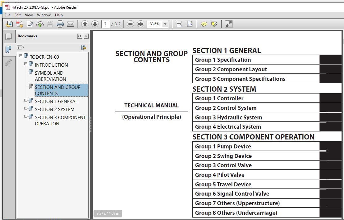
TODCR-EN-00....................................................................................................................................................................  1
	INTRODUCTION...............................................................................................................................................................  3
		To The Reader..........................................................................................................................................................  3
		Additional References..................................................................................................................................................  3
		Manual Composition.....................................................................................................................................................  3
		Page Number............................................................................................................................................................  3
		Safety Alert Symbol and Headline Notations.............................................................................................................................  4
		Units Used.............................................................................................................................................................  4
	SYMBOL AND ABBREVIATION....................................................................................................................................................  5
	SECTION AND GROUP CONTENTS.................................................................................................................................................  7
	SECTION 1 GENERAL..........................................................................................................................................................  9
		Group 1 Specification.................................................................................................................................................. 11
			Specifications..................................................................................................................................................... 11
			Working Ranges (Grouser shoe)...................................................................................................................................... 12
		Group 2 Component Layout............................................................................................................................................... 13
			Main Component..................................................................................................................................................... 13
			Electrical System (Overview)....................................................................................................................................... 14
			Engine............................................................................................................................................................. 15
			Electrical System (In Cab)......................................................................................................................................... 15
			Electrical System (Rear Tray)...................................................................................................................................... 16
			Electrical System (Monitors)....................................................................................................................................... 17
			Electrical System (Switch Panel)................................................................................................................................... 18
			Electrical System (Around Air Cleaner)............................................................................................................................. 19
			Electrical System (Relays)......................................................................................................................................... 20
			Pump Device........................................................................................................................................................ 21
			Control Valve...................................................................................................................................................... 22
			Signal Control Valve............................................................................................................................................... 22
			Swing Device....................................................................................................................................................... 24
			Travel Device...................................................................................................................................................... 24
			3-Spool Solenoid Valve Unit........................................................................................................................................ 25
			Layout of Attachment Spec. Parts................................................................................................................................... 26
		Group 3 Component Specifications....................................................................................................................................... 29
			Engine............................................................................................................................................................. 29
			Engine Accessories................................................................................................................................................. 33
			Hydraulic Component................................................................................................................................................ 34
			Electrical Component............................................................................................................................................... 38
	SECTION 2 SYSTEM........................................................................................................................................................... 41
		Group 1 Controller..................................................................................................................................................... 43
			Outline............................................................................................................................................................ 43
			CAN (Network Provided for Machine)................................................................................................................................. 44
		Group 2 Control System................................................................................................................................................. 47
			Outline............................................................................................................................................................ 47
			Engine Control..................................................................................................................................................... 50
			Pump Control....................................................................................................................................................... 72
			Valve Control...................................................................................................................................................... 82
			Other Control...................................................................................................................................................... 94
		Group 3 Hydraulic System............................................................................................................................................... 99
			Outline............................................................................................................................................................ 99
			Pilot Circuit......................................................................................................................................................100
			Main Circuit.......................................................................................................................................................110
		Group 4 Electrical System..............................................................................................................................................123
			Outline............................................................................................................................................................123
			Main Circuit.......................................................................................................................................................124
			Electric Power Circuit (Key Switch: OFF)...........................................................................................................................126
			CAN Circuit........................................................................................................................................................128
			Accessory Circuit..................................................................................................................................................130
			Preheating Circuit (Key Switch: ON, START).........................................................................................................................132
			Starting Circuit (Key Switch: START)...............................................................................................................................134
			Charging Circuit (Key Switch: ON)..................................................................................................................................138
			Surge Voltage Prevention Circuit...................................................................................................................................142
			Pilot Shut-Off Circuit (Key switch: ON)............................................................................................................................144
			Engine Stop Circuit................................................................................................................................................146
			Accessory Circuit..................................................................................................................................................149
			Work Light Circuit.................................................................................................................................................150
			Wiper/Washer Circuit...............................................................................................................................................152
			Cab Light Circuit..................................................................................................................................................154
	SECTION 3 COMPONENT OPERATION..............................................................................................................................................159
		Group 1 Pump Device....................................................................................................................................................161
			Outline............................................................................................................................................................161
			Main Pump..........................................................................................................................................................162
			Regulator..........................................................................................................................................................166
			Solenoid Valve.....................................................................................................................................................184
			Pilot Pump.........................................................................................................................................................186
			Pump Delivery Pressure Sensor......................................................................................................................................186
			Pump Control Pressure Sensor.......................................................................................................................................186
			N Sensor (Engine Speed Sensor).....................................................................................................................................187
		Group 2 Swing Device...................................................................................................................................................189
			Outline............................................................................................................................................................189
			Swing Reduction Gear...............................................................................................................................................190
			Swing Motor........................................................................................................................................................191
			Swing Parking Brake................................................................................................................................................192
			Valve Unit.........................................................................................................................................................194
		Group 3 Control Valve..................................................................................................................................................197
			Outline............................................................................................................................................................197
			Hydraulic Circuit..................................................................................................................................................218
			Flow Combiner Valve................................................................................................................................................224
			Main Relief Valve..................................................................................................................................................226
			Overload Relief Valve (with Make-Up Function)......................................................................................................................230
			Regenerative Valve.................................................................................................................................................234
			Anti-Drift Valve...................................................................................................................................................238
			Flow Rate Control Valve............................................................................................................................................242
			Digging Regenerative Valve.........................................................................................................................................246
			Boom Lower Meter-In Cut Valve......................................................................................................................................248
			Bypass Shut-Out Valve..............................................................................................................................................250
		Group 4 Pilot Valve....................................................................................................................................................253
			Outline............................................................................................................................................................253
			Operation (Front Attachment / Swing and Travel Pilot Valves).......................................................................................................255
			Operation (Auxiliary Pilot Valve)..................................................................................................................................263
			Shockless Function (Only for Travel Pilot Valve)...................................................................................................................268
		Group 5 Travel Device..................................................................................................................................................269
			Outline............................................................................................................................................................269
			Travel Reduction Gear..............................................................................................................................................270
			Travel Motor.......................................................................................................................................................272
			Parking Brake......................................................................................................................................................274
			Travel Brake Valve.................................................................................................................................................276
			Overload Relief Valve..............................................................................................................................................280
			Travel Mode Control................................................................................................................................................282
		Group 6 Signal Control Valve...........................................................................................................................................287
			Outline............................................................................................................................................................287
			Pilot Port.........................................................................................................................................................288
			Shuttle Valve......................................................................................................................................................293
			Shockless Valve....................................................................................................................................................296
			Pump 1 and 2 Flow Rate Control Valve...............................................................................................................................300
			Bucket Flow Rate Control Valve Control Spool, Flow Combiner Valve Control Spool, Swing Parking Brake Release Spool, Arm 1 Flow Rate Control Valve Control Spool....302
		Group 7 Others (Upperstructure)........................................................................................................................................305
			Pilot Shut-Off Solenoid Valve......................................................................................................................................305
			Solenoid Valve.....................................................................................................................................................307
			Pilot Relief Valve.................................................................................................................................................310
			EC Motor...........................................................................................................................................................310
		Group 8 Others (Undercarriage).........................................................................................................................................311
			Swing Bearing......................................................................................................................................................311
			Center Joint.......................................................................................................................................................312
			Track Adjuster (Front Idler Integrated Type).......................................................................................................................313
Please Note:
⦁ This is the SAME manual used by the dealers to troubleshoot any faults in your vehicle. This can be yours in 2 minutes after the payment is made.
⦁ Contact us at [email protected] should you have any queries before your purchase or that you need any other service / repair / parts operators manual.


