

Hitachi ZX210X-6 210LCX-6 Hydraulic Excavator Technical+Electrical-Hydraulic Circuit+Workshop Manual
FILE DETAILS:
Hitachi ZX210X-6 210LCX-6 Hydraulic Excavator Technical+Electrical-Hydraulic Circuit+Workshop Manual
This Listing includes all of the manuals mentioned below:
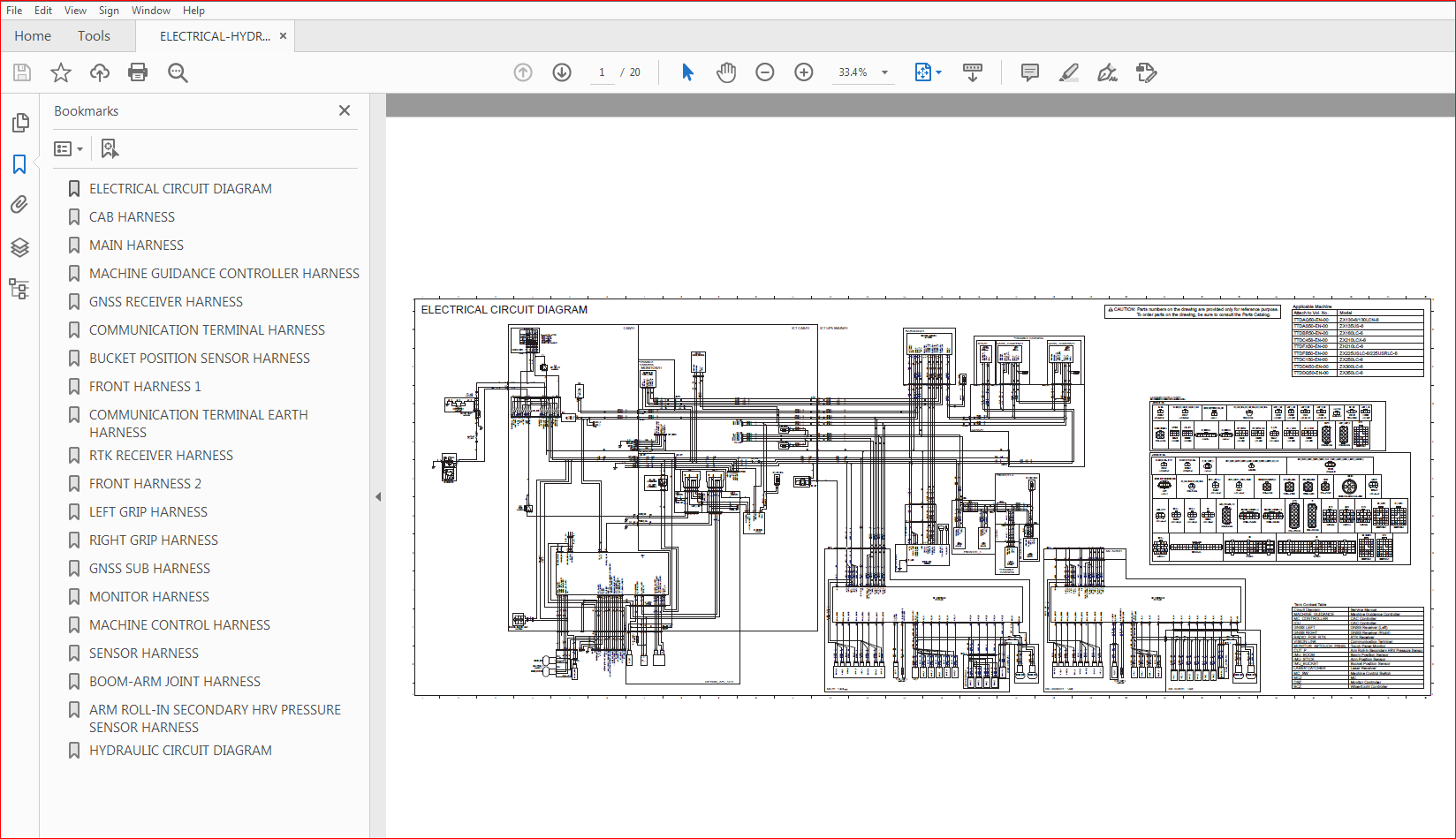
Hitachi ZX 210X-6 210LCX-6 Electrical-Hydraulic Circuit Diagram
Hitachi ZX 210X-6 210LCX-6 Hydraulic Excavator Technical Manual
Hitachi ZX 210X-6 210LCX-6 Hydraulic Excavator Workshop Manual
DESCRIPTION:
Hitachi ZX210X-6 210LCX-6 Hydraulic Excavator Technical+Electrical-Hydraulic Circuit+Workshop Manual
INTRODUCTION:
TO THE READER:
• This manual is written for an experienced technician to provide technical information needed to maintain and repair this machine.
• Be sure to thoroughly read this manual for correct product information and service procedures.
• If you have any questions or comments, at if you found any errors regarding the contents of this manual, please contact using “Service Manual Revision Request Form” at the end of this manual.
ADDITIONAL REFERENCES:
• Please refer to the materials listed below in addition to this manual.
• The Operator’s Manual
• The Parts Catalog
• The Engine Manual
• Parts Catalog of the Engine
• Hitachi Training Material
MANUAL COMPOSITION:
• This manual consists of three portions: the Technical Manual (Operational Principle), the Technical Manual (Troubleshooting) and the Workshop Manual.
• Information included in the Technical Manual (Operational Principle): technical information needed for redelivery and delivery, operation and activation of all devices and systems.
• Information included in the Technical Manual (Troubleshooting): technical information needed for operational performance tests, and troubleshooting procedures.
• Information included in the Workshop Manual: technical information needed for maintenance and repair of the machine, tools and devices needed for maintenance and repair, maintenance standards, and removal/installation and assemble/ disassemble procedures.
TABLE OF CONTENTS:
Hitachi ZX210X-6 210LCX-6 Hydraulic Excavator Technical+Electrical-Hydraulic Circuit+Workshop Manual
- Hitachi ZX 210X-6 210LCX-6 Hydraulic Excavator Technical Manual
SECTION 1
GENERAL
Group 1 Specifications
Specifications (2DMC)T1-1-1
Specifications (3DMC)T1-1-2
Working Ranges (Grouser shoe)T1-1-3
Group 2 Component Layout
Electrical System (2DMC, 3DMC)T1-2-1
Electrical System (2DMC, 3DMC)T1-2-2
Hydraulic Component (2DMC, 3DMC)T1-2-3
Group 3 Component Specifications
Hydraulic Component (only for 2DMC, 3DMC)T1-3-1
Electrical Components (only for 2DMC, 3DMC)T1-3-2
SECTION 2
SYSTEM
Group 1 Controller
Outline T2-1-1
CAN Circuit T2-1-4
Group 2 Control System
Outline T2-2-1
Front Attachment Semiautomatic Control T2-2-5
Engine Control (MC, ECM)T2-2-13
Valve Control (MC)T2-2-17
Group 3 Hydraulic System
Outline T2-3-1
Front Attachment Semiautomatic
Control Pilot Circuit T2-3-2
SECTION 3
COMPONENT OPERATION
Group 1 8-Spool Solenoid Valve Unit (for
Machine Control)
8-Spool Solenoid Valve Unit
(for Machine Control) T3-1-1
Group 2 5-Spool Selector Valve Unit (for
Machine Control)
5-Spool Selector Valve Unit
(for Machine Control) T3-2-1
SECTION 4
OPERATIONAL PERFORMANCE TEST
Group 1 Introduction
Outline T4-1-1
Group 2 Operational Performance Test and
Standard
Operational Performance Test and
Standard Table T4-2-1
Group 3 Calibration
Accuracy confirmation of 2D T4-3-1
Operation of the Total Station (TSC3)T4-3-20
Mobile Station GNSS SettingT4-3-26
Observation of Terrain Feature Points
by Mobile StationsT4-3-32
Accuracy confirmation of 3DT4-3-35
Bucket Dimension MeasurementT4-3-44
Bucket Setting Change Method of
Bucket less MachineT4-3-53
Laser Catcher Position Accuracy ConfirmationT4-3-57
3DMG CalibrationT4-3-72
MC Solenoid Valve for MC CalibrationT4-3-88
Bleed Air from Solenoid Valve of MC T4-3-103
[Setting Method] Gradient in Front/
Back Direction (Horizontal surface/Slope) T4-3-117
[Setting Method] Gradient in Left/
Right Direction (Horizontal surface/Slope) T4-3-123
[Setting Method] Altitude Offset T4-3-127
Wi-Fi Network T4-3-131
Metering Calibration T4-3-133
MC Accuracy Check T4-3-165
SECTION 5
TROUBLESHOOTING
Group 1 Diagnosing Procedure
Introduction T5-1-1
Group 2 Troubleshooting A
Troubleshooting A (Base Machine Diagnosis
by Using Fault Codes) Procedure T5-2-1
Computer Aided Construction Controller
(CAC Controller) Fault Code List T5-2-3
CAC Controller Fault Code 19001 to 19002T5-2-15
CAC Controller Fault Code 19003T5-2-16
CAC Controller Fault Code 19031 to 19033T5-2-17
CAC Controller Fault Code 19034 to 19039T5-2-18
CAC Controller Fault Code 19040 to 19042T5-2-19
CAC Controller Fault Code 19045 to 19046T5-2-20
CAC Controller Fault Code 19047T5-2-21
CAC Controller Fault Code 19081T5-2-22
CAC Controller Fault Code 19120T5-2-23
CAC Controller Fault Code 19121T5-2-24
CAC Controller Fault Code 19122T5-2-25
CAC Controller Fault Code 19123T5-2-26
CAC Controller Fault Code 19125T5-2-27
CAC Controller Fault Code 19127T5-2-28
CAC Controller Fault Code 19128T5-2-29
CAC Controller Fault Code 19130T5-2-30
CAC Controller Fault Code 19015 to 19017T5-2-31
CAN1 (CAC) Harness CheckT5-2-32
CAC Controller Fault Code 19022 to 19028T5-2-35
2DCAN (2D System) Harness CheckT5-2-36
3DCAN (3D System) Harness CheckT5-2-38
CAC Controller Fault Code 19051T5-2-40
Group 3 Troubleshooting B
Troubleshooting B (Machine Diagnosis
by Using Trouble Symptom) Procedure T5-3-1
Relationship between Machine Trouble Symptoms
and Related Parts T5-3-3
Correlation between Trouble Symptoms
and Part Failures T5-3-9
QuestionnaireT5-3-73
[Check Procedure 1] Software versionT5-3-77
[Check Procedure 2] GNSS, DesignT5-3-80
[Check Procedure 3] Bucket weight settingT5-3-83
Bucket Weight SettingT5-3-83
[Check Procedure 4] Tooth lengthT5-3-84
[Check Procedure 5] CorrectionT5-3-89
[Check Procedure 6] GNSS informationT5-3-93
[Check Procedure 7] GNSS accuracy
tolerance settingT5-3-96
[Check Procedure 8] Radio condition T5-3-102
Group 4 Troubleshooting C
Machine Diagnosis by Using Machine
Guidance System Status Indicator T5-4-1
- Hitachi ZX 210X-6 210LCX-6 Hydraulic Excavator Workshop Manual
SECTION 1 GENERAL INFORMATION
Group 1 Precautions for Disassembling and Assembling
Group 2 Tightening
Group 3 Painting
Group 4 Bleeding Air
Group 5 Preparation
SECTION 2 UPPERSTRUCTURE
Group 1 8-Spool Solenoid Valve Unit for Machine Control
Group 2 5-Spool Control Valve Unit for Machine Control
Group 3 Body Angle Sensor
Group 4 Boom Position Sensor
Group 5 Arm Position Sensor
Group 6 Bucket Position Sensor
Group 7 GNSS Receiver (Right) (Left)
Group 8 Communication Terminal
Group 9 RTK Receiver
VIDEO PREVIEW OF THE MANUAL:

IMAGES PREVIEW OF THE MANUAL:
PLEASE NOTE:
- This is the same manual used by the DEALERSHIPS to SERVICE your vehicle.
- The manual can be all yours – Once payment is complete, you will be taken to the download page from where you can download the manual. All in 2-5 minutes time!!
- Need any other service / repair / parts manual, please feel free to contact us at heydownloadss @gmail.com . We may surprise you with a nice offer


