

Genie TMZ-34/19 Service Manual 52075 – PDF DOWNLOAD
Language : English
Pages : 138
Downloadable : Yes
File Type : PDF

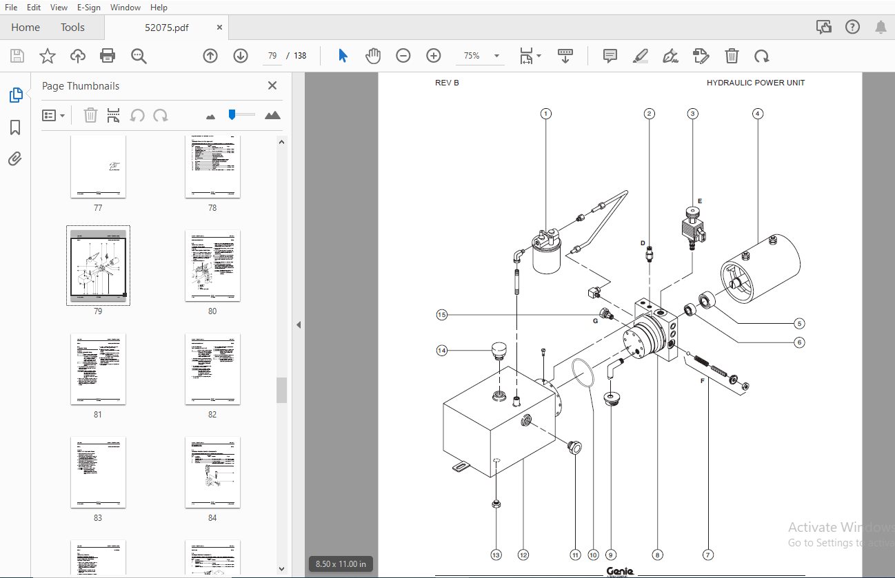
Table of Contents:
Genie TMZ-34/19 Service Manual 52075 – PDF DOWNLOAD
Table of Contents..............................................................................................  5
Section 1 • Safety Rules.......................................................................................  3
Section 2 • Specifications - Rev C............................................................................. 11
	Machine Specifications..................................................................................... 11
	Performance Specifications................................................................................. 11
	Hydraulic Specifications................................................................................... 12
	Manifold Component Specifications.......................................................................... 13
	Machine Torque Specifications.............................................................................. 13
	Hydraulic Hose and Fitting Torque Specifications........................................................... 14
	SAE and Metric Fasteners Torque Charts..................................................................... 15
Section 3 • Scheduled Maintenance Procedures................................................................... 17
	Introduction............................................................................................... 17
	Pre-delivery Preparation................................................................................... 19
	Maintenance Inspection Report.............................................................................. 21
	Checklist A Procedures - Rev C............................................................................. 22
		A-1  Perform Pre-operation Inspection.................................................................. 22
		A-2  Perform Function Tests............................................................................ 22
		A-3  Perform Hitch Maintenance - ANSI Models........................................................... 23
		A-4  Perform Axle Maintenance - ANSI Models............................................................ 23
		A-5  Perform Axle Maintenance - CE Models.............................................................. 24
		A-6  Perform Axle Maintenance - CE Models.............................................................. 24
		A-7  Perform Axle Maintenance - ANSI Models............................................................ 25
		A-8  Perform Axle Maintenance - ANSI Models............................................................ 25
		A-9  Perform Axle Maintenance - CE Models.............................................................. 26
		A-10  Perform 30 Day Service........................................................................... 26
		A-11  Grease the Turntable Rotation Bearing and Rotate Gear............................................ 27
	Checklist B Procedures - Rev C............................................................................. 28
		B-1  Inspect the Batteries............................................................................. 28
		B-2  Inspect the Electrical Wiring..................................................................... 29
		B-3  Test the Emergency Stop........................................................................... 30
		B-4  Test the Key Switch............................................................................... 30
		B-5  Test the Manual Lowering Operation................................................................ 31
		B-6  Inspect the Tires and Wheels (including lug nut or lug bolt torque)............................... 32
		B-7  Service the Tongue Jack........................................................................... 32
		B-8  Inspect the Parking Brake......................................................................... 33
		B-9  Test the Horn..................................................................................... 34
		B-10  Test the Flashing Beacon (if equipped)........................................................... 34
		B-11  Test the Platform Rotation (if equipped)......................................................... 35
		B-12  Inspect the Hydraulic Tank Cap Venting System.................................................... 35
		B-13  Perform Hitch Maintenance - ANSI Models.......................................................... 36
		B-14  Perform Axle Maintenance - ANSI Models........................................................... 36
		B-15  Perform Hydraulic Oil Analysis................................................................... 37
	Checklist C Procedures - Rev C............................................................................. 38
		C-1  Replace the Hydraulic Tank Breather Cap - Models with Optional Hydraulic Oil...................... 38
		C-2  Perform Axle Maintenance - ANSI Models............................................................ 38
		C-3  Perform Hitch Maintenance - CE Models............................................................. 39
	Checklist D Procedures - Rev C............................................................................. 40
		D-1  Check the Turntable Rotation Bearing Bolts........................................................ 40
		D-2  Inspect for Turntable Bearing Wear................................................................ 41
		D-3  Replace the Hydraulic Tank Return Filter.......................................................... 42
		D-4  Perform Axle Maintenance - ANSI Models............................................................ 43
		D-5  Perform Hitch Maintenance - ANSI Models........................................................... 43
	Checklist E Procedure - Rev C.............................................................................. 44
		E-1  Test or Replace the Hydraulic Oil................................................................. 44
Section 4 • Repair Procedures.................................................................................. 45
	Introduction............................................................................................... 45
	Platform Controls - Rev C.................................................................................. 46
		1-1  Circuit Board..................................................................................... 46
		1-2  Membrane Overlay.................................................................................. 47
	Platform Components - Rev C................................................................................ 49
		2-1  Platform.......................................................................................... 49
		2-2  Platform Rotator (if equipped).................................................................... 49
	Jib Boom Components - Rev C................................................................................ 52
		3-1  Jib Boom.......................................................................................... 52
		3-2  Jib Boom Cylinder................................................................................. 54
	Boom Components - Rev B.................................................................................... 56
		4-1  Boom.............................................................................................. 56
		4-2  Lift Cylinders.................................................................................... 62
	Ground Controls - Rev C.................................................................................... 64
		5-1  Ground Control Keypad Circuit Board............................................................... 64
		5-2  CPU Circuit Board................................................................................. 66
		5-3  Connector Circuit Board........................................................................... 66
		5-4  Software Configuration............................................................................ 67
		5-5  Membrane Overlay.................................................................................. 69
		5-6  Level Sensor...................................................................................... 71
		5-7  Interacter Battery Charger........................................................................ 74
		5-8  Lester Battery Charger............................................................................ 76
	Hydraulic Power Unit - Rev B............................................................................... 78
		6-1  Hydraulic Power Unit Components................................................................... 78
		6-2  Valve Adjustments - Hydraulic Power Unit.......................................................... 80
		6-3  Hydraulic Pump.................................................................................... 81
	Manifolds - Rev C.......................................................................................... 84
		7-1  Turntable Rotation Manifold Components............................................................ 84
		7-2  Valve Adjustments - Turntable Rotation Manifold................................................... 85
		7-3  Outrigger Manifold Components..................................................................... 86
		7-4  Valve Coils....................................................................................... 87
	Turntable Rotation Components - Rev B...................................................................... 89
		8-1  Turntable Rotation Motor.......................................................................... 89
	Axle Components - Rev B.................................................................................... 90
		9-1  Axle.............................................................................................. 90
		9-2  Hub and Bearings.................................................................................. 90
	Trailer Components - Rev C................................................................................. 91
		10-1  Trailer Brakes................................................................................... 91
		10-2  Parking Brake.................................................................................... 91
	Outrigger Components - Rev B............................................................................... 92
		11-1  Outrigger Components............................................................................. 92
		11-2  Outrigger Cylinder............................................................................... 93
Section 5 • Troubleshooting Flow Charts........................................................................ 95
	Introduction............................................................................................... 95
	Fault Code Chart (after serial number T3402-115) - Rev A................................................... 97
	Chart 1  All Functions Will Not Operate (before serial number T3400-001) - Rev B...........................100
	Chart 2  Pump Motor Will Not Operate - Rev B...............................................................102
	Chart 3  All Functions Inoperative, Power Unit Starts and Runs - Rev B.....................................103
	Chart 4  Ground Controls Inoperative - Rev B...............................................................104
	Chart 5  Platform Controls Inoperative - Rev B.............................................................105
	Chart 6  Jib Boom Up Function Inoperative - Rev B..........................................................106
	Chart 7  Jib Boom Down Function Inoperative - Rev B........................................................107
	Chart 8  Primary Boom Up Function Inoperative - Rev B......................................................109
	Chart 9  Primary Boom Down Function Inoperative - Rev B....................................................110
	Chart 10  Secondary Boom Up Function Inoperative - Rev B...................................................112
	Chart 11  Secondary Boom Down Function Inoperative - Rev B.................................................113
	Chart 12  Turntable Rotate Left Function Inoperative - Rev B...............................................115
	Chart 13  Turntable Rotate Right Function Inoperative - Rev B..............................................116
	Chart 14  Parking Brake Function Inoperative - Rev A.......................................................117
Section 6 • Schematics.........................................................................................119
	Introduction...............................................................................................119
	Electrical Component and Wire Color Legends - Rev B........................................................120
	Limit Switch Legend - Rev A................................................................................121
	Trailer Lighting Wiring Diagram - Rev A....................................................................122
	Electrical Symbols Legend - Rev A..........................................................................123
	Electrical Schematic, Models with Manual Outriggers (from serial number T3498-001 to T3499-361) - Rev B....124
	Electrical Schematic, Models with Manual Outriggers (from serial number T3499-362 to T3499-769) - Rev A....125
	Electrical Schematic, Models with Manual Outriggers (from serial number T3400-001) - Rev B.................126
	Electrical Schematic, Models with Hydraulic Outriggers - Rev B.............................................128
	Hydraulic Symbols Legend and Component Reference - Rev A...................................................131
	Hydraulic Schematic, Models with Manual Outriggers (from serial number T3498-001 to T3499-769) - Rev A.....132
	Hydraulic Schematic, Models with Manual Outriggers (from serial number T3400-001 to T3400-265) - Rev A.....133
	Hydraulic Schematic, Models with Manual Outriggers (after serial number T3400-265) - Rev A.................134
	Hydraulic Schematic, Models with Hydraulic Outriggers (before serial number T3400-266) - Rev A.............135
	Hydraulic Schematic, Models with Hydraulic Outriggers (after serial number T3400-265) - Rev A..............136
S.S 04/24


