

Fiat Trattori 580 580 DT 680 680 DT (570 – 670) Workshop Manual – PDF DOWNLOAD
FILE DETAILS:
Fiat Trattori 580 580 DT 680 680 DT (570 – 670) Workshop Manual – PDF DOWNLOAD
Language : English
Pages : 192
Downloadable : Yes
File Type : PDF
DESCRIPTION:
Fiat Trattori 580 580 DT 680 680 DT (570 – 670) Workshop Manual – PDF DOWNLOAD
FOREWORD:
• The manual is divided into separately numbered sections.
• Two-digit sections contain
– Tractor specification (00).
– Tractor sub-assembly specification and data (10 Engine, 20 Power Train , etc.).
• Three-digit sections dea/ with the overhaul of the sub-assemblies whose data are
listed in the two-digit sections.
The first two digits are the same as those of the associated data sections (e.g. 20
– Power Train 201 – Clutch 202 Transmission, splitter etc.).
• A contents list is provided to facilitate retrieval of desired information.
• Each sheet carries the print number of the manual and the date of issue in the
bottom right-hand corner of the front page.
• Revised sheets wi/1 carry the same print number followed by a number (e.g. first
revision 603.54.202 I 1, second revision 603. 54.202 I 2, etc) and next issue date.
Revised sheets wi/1 be accompanied by the updated contents sheet.
• Wear limits recommended for soma parts are not binding, being given for
guidance only.
IMAGES PREVIEW OF THE MANUAL:
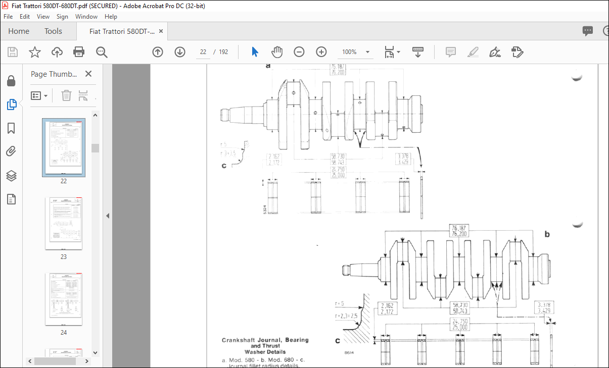
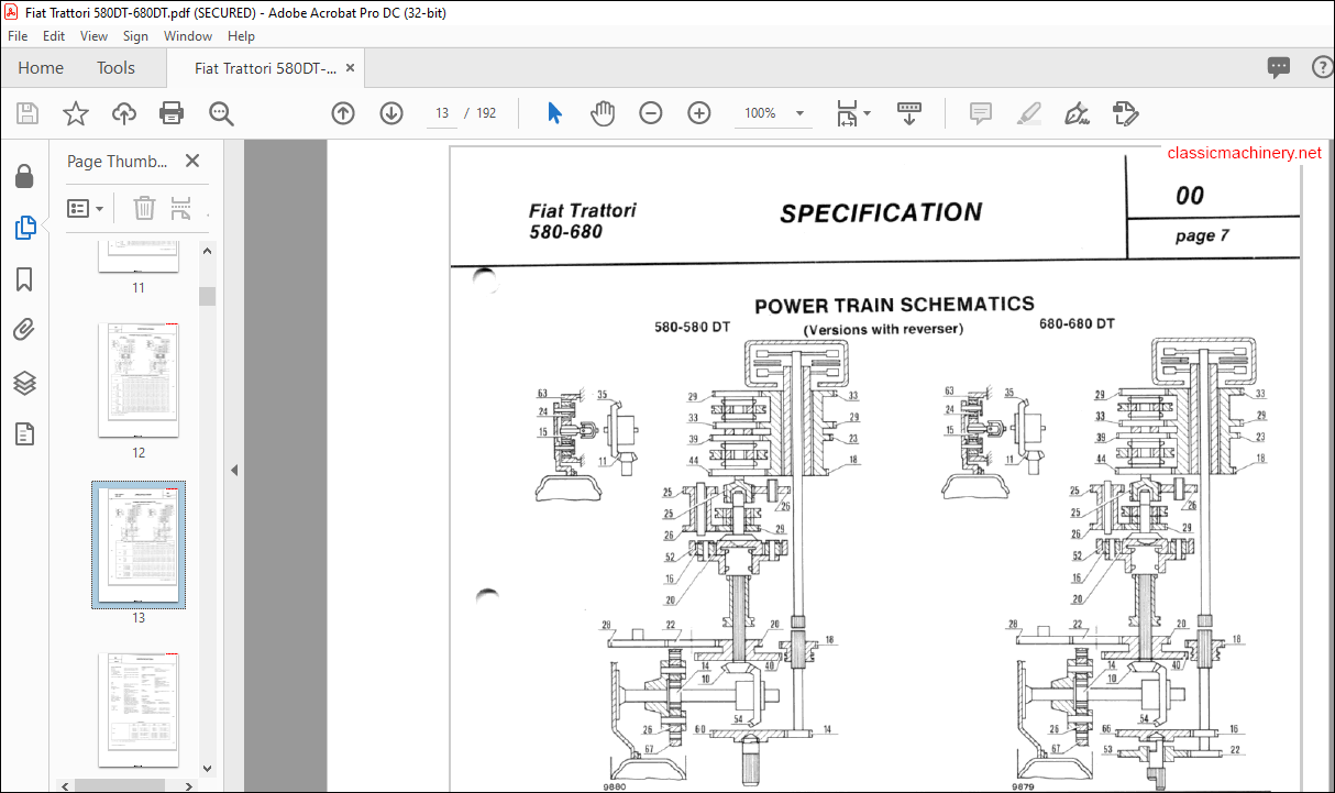
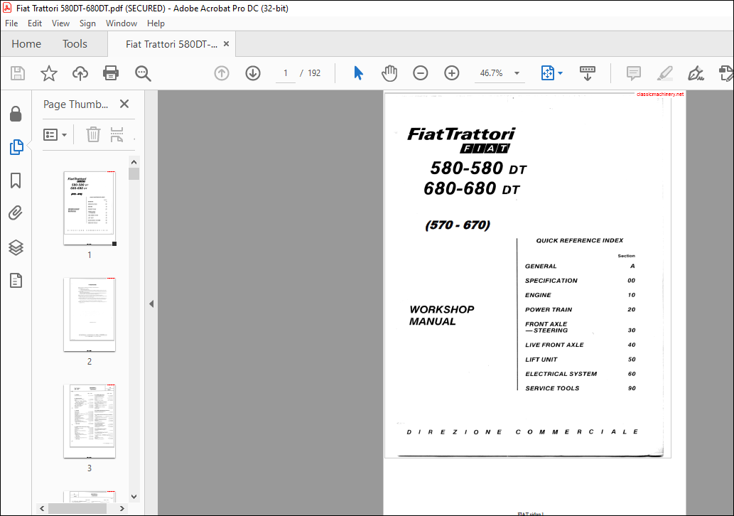
TABLE OF CONTENTS:
Fiat Trattori 580 580 DT 680 680 DT (570 – 670) Workshop Manual – PDF DOWNLOAD
A – GENERAL
201 – POWER TRAIN: Clutch
classicmachinery. net
General instructions 5-6 1 IX-1979 To overhaul FERODO clutch 1-2 IX-1979
To Adjust FERODO Clutch 3 IX-1979
To Overhaul LUK or O.M .G .
00 – SPECIFICATION Clutch 3-4-5 IX-1979
ldentification Data – Weights 1 IX-1979 To Adjust LUK or O.M.G .
Clutch 5-6 IX-1979 Eng ine 2-3 IX-1979 To adjust Clutch Linkage 6-7 IX-1979 Power Train – Brakes – Steering –
Front Ax le – Live Front Axle – Rear
wheels – Power T ake-Off 4 IX-1979 202 – POWER TRAIN : Transmission
Power Train Schematics 5-6-7 IX-1979 Splitter and Crawler Gear
Lift – Towing Allachments – Salla- Sections Th rough 8-speed Transting
– Tyre sizes 8 IX-1979 smission IX-1979
Body – Electrical System 9 IX-1979 Sections Through 12-speed Tran-
Heavy Duty Tractors 9 IX-1979 smission 2 IX-1979
Dimensions 10 IX-1979 Longitudinal Section Through
Capacities 11 IX -1979 Crawler Gear 2 IX-1979
Synchromesh 3 IX-1979
10 – ENGINE 203 – POWER TRAIN: Mechanical Reverser
Engine Block 1- 2 IX-1979 Sections Through Transmission
Cylinder Head 2-3 IX-1979 WithMechanical Reverser 1 1 IX-1979
Crank Gear 3-4-5-6 -7-8 IX-1979
Dynamic Balancer (680 Tractor) 9 IX-1979
Valve Gear 10-11-12-13 IX-1979 204 – POWER TRAIN : Rear Bevel Drive and Dlfleren-
To Adjust Valve Clearance 13 IX-1979 tial
Lubrication System 14 IX-1979 To Ad j ust Bevel Drive 1-2-3-4-5-6 IX-1979 Cooling System 15 IX-1979 To Assemble a n d Adjust Differential Cooling System Diagrams 16 IX -1979 Lock 6 IX-1979 Lubrica tion System Diagrams 17-18 IX-1979 To Adjust Differential Lock Contro l 6 IX-1979 Fuel System 19-20-21-22 IX-1979 Sections Through Bevel Drive and Performance Data 23 IX -1979 Di f ferential 7 IX-1979 Torque Tightening Figures 24 IX-1979 To Adjust Differential 8 IX-1979 Longitudina l Section Through Engine
580 Tractor 25 IX-1979 205 – POWER TRAIN : Brakes
– 680 Tractor 26 IX-1979 Hydraulic Brake System 1 IX-1979
To Adjust Brake Pedals 2-3 IX -1979
To Bench Test Master Cylinder
20 – POWER TRAIN : Spec ification and Data To Bleed The Brake System 3-4 IX-1979
Parking Brake 5 IX-1979
Clu tches 1-2-3 IX-1979
Transmission and Splitter 3-4 IX-1979
206 – POWER TRAIN : Final Drives Crawler Gear 4 IX-1979
Reverser 4 IX-1979 Longitudinal Section Through
Rear Bevel Drive and Dif ferential 5 IX-1979 Final Drive 1 1 IX-1979
Brakes 6-7 IX-1979
Final Drive 7 IX-1979 207 – POWER TRAIN : Power Take -Olf
Power Take-Off 8 IX-1979 Longitudinal Seclions 1-2 I IX-1979
Tightening Torque Figures 9-10 IX-1979
Longitudinal Section Through Po-
30 – FRONT AXLE – STEERING : Specification and wer Train
– 580 Tractor 11 IX-1979 Data
– 680 Tractor 12 IX-1979 Front Axle IX-1979
Cross Section Through Power Train Manual Steering – Power
– 580 Tractor 13 IX -1979 Steering 2-3 IX-1979
– 680 Tractor 14 IX -1979 Torque Tightening Figures 4 IX -1979
301 – FRO NT AXLE – STEERING : Front Axle
To Adjust Wheel Beari ngs 1 I IX-1979
To lnspect Axle 2 IX-1979
302 – FRO NT AXLE · STEERING : Manual Steering
To Overhaul Steering Uni! 1 I IX- 1979
Linkage 2 IX – 1979
303 · FRO NT AXLE – STEERING : Power Steering
To Overhaul Power Steering 1 IX – 1979
To Overhaul Hydra u lic Cylinder 2 IX-1979
To Overhaul Steering Pump and
R eservoir – To Bleed the Hydraulic
Syst em
To Adjust Valve Setti ngs
Trouble S hooting Chart
Power Steering Diagrams and Sections
40 – LIVE FRONT AXLE : Specification and Data
Front A xle 1-2 IX-1979
Axle Orive – Drive Shatt 2 IX-1979
TorqueTig hteningFigures 3 IX-1979
401 • LIVE FRONT AXLE : Front Axle
To Adjust King Pin Bearings
T o Adjust Whee l Beari ngs
To Adjust Beve l Drive
Live Front Axle Sections
To Adjust Differential
50. HYD RAULIC LIFT UNIT: Specification and Data
Lift 1-2 IX-1979
LiftPump 3 IX -1979
lmplement Attachment 4 IX-1979
Trouble Shooting Chart 5 IX -1979
Tighteni n g Torque Figures 6 IX-1979
501 • HYDRAULIC LIFT UNIT: Lift
Hydraulic System Diagrams
Lift Operati on – Lift Schematics
Sect,ons Through Lift A r ms
DIREZIONE COMMERCIALE
Valve
To Check Unload Valve
13 I X-19 79
14 I X-1979
502 – HYDRAULIC LIFT UNIT: Lift Pump
To Overhaul 1 I I X- 1979
2 I X-1979 Outpul Test – Oil Filte r
503 – HYDRAULIC LIFT UNIT: lmplement Attachmen t
To Adjust Sensing Bar End Float 1 I I X-1979
Draught Control Device 1-2 I X-1979
504. HYDRAULIC LIFT UNIT: Remote Control Device
Specification and Data
Torque Tig hte n ing Figures
To Disassemble
Desc rip lio n and Ope ra t ion
To Ad ju st Relief Valve
-Spool Return Test
Leakage Test
505. HYDRAULIC LIFT UNIT: Auxiliary Cylinder
Specification and Data 1 I IX-19 7 9
T ighte ning Torque Figures 1 IX-1 979
Hydraulic Syst em Diagram 2 IX -1979
60. ELECTRICAt. SYSTEM : Speclfication and Data
Charging Syst em
MA RE LLI Starter
LUC AS Starter
BOSCH Starter
Battery – Fuses
Ligh ting – Signals • Accessori es
Switches – Turn Signal
Switch
lnstruments and Controls
C.A.V . lnjec lion P ump
Start-Retard Dev i ce
Wiring Diagrams
90 – SERVICE TOOLS
VIDEO PREVIEW OF THE MANUAL:
PLEASE NOTE:
- This is the SAME exact manual used by your dealers to fix your vehicle.
- The same can be yours in the next 2-3 mins as you will be directed to the download page immediately after paying for the manual.
- Any queries / doubts regarding your purchase, please feel free to contact [email protected]
S.V


