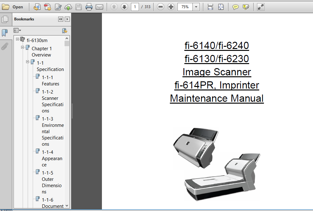
Fi 6130 Fi 6230 Fi 6140 Fi 6240 Image Scanner Fi 614pr Imprinter Maintenance Manual Parts List
FILE DETAILS:
Fi 6130 Fi 6230 Fi 6140 Fi 6240 Image Scanner Fi 614pr Imprinter Maintenance Manual Parts List
FILE TYPE:PDF
DOWNLOADABLE:YES
MANUAL LANGUAGE:ENGLISH
PAGES:313
DESCRIPTION:
Fi 6130 Fi 6230 Fi 6140 Fi 6240 Image Scanner Fi 614pr Imprinter Maintenance Manual Parts List
This manual provides the technical information such as maintenance, troubleshooting procedure and parts replacement procedure for field Engineers on fi-6140/fi-6240/fi-6130/fi-6230 image scanner. This manual is for use as a maintenance tool only.
For information that is not contained in this manual, refer to the following manuals:
Item Manuals P/N * Remarks
1 fi-6140/fi-6240 Image Scanner Operator’s Guide P3PC-2062-xxEN Attached to fi-6140/fi-6240 (CD-ROM)
2 fi-6140/fi-6240 Image Scanner Getting Started P3PC-2052-xxEN Attached to fi-6140/fi-6240 (booklet)
3 fi-6130/fi-6230 Image Scanner Operator’s Guide P3PC-2162-xxEN Attached to fi-6130/fi-6230 (CD-ROM)
4 fi-6130/fi-6230 Image Scanner Getting Started P3PC-2152-xxEN Attached to fi-6130/fi-6230 (booklet)
5 fi-614PR Imprinter Operator’s Guide P3PC-2112-xxEN Attached to fi-614PR (CD-ROM)
6 fi-6140/fi-6240/fi-6130/fi-6230/fi-614PR
Illustrated Parts Catalog
P4PA03540-B0XX/6
TABLE OF CONTENTS:
Fi 6130 Fi 6230 Fi 6140 Fi 6240 Image Scanner Fi 614pr Imprinter Maintenance Manual Parts List
Chapter 1 Overview 10
1-1 Specification 10
1-1-1 Features 10
1-1-2 Scanner Specifications 11
1-1-3 Environmental Specifications 12
1-1-4 Appearance 13
1-1-5 Outer Dimensions 16
1-1-6 Document Specifications 17
1-1-7 Multi feed Detection Condition 18
1-2 Scanner Configuration 19
1-2-1 ADF Unit 19
1-2-2 Reading Station 20
1-2-3 Controller 22
1-2-4 Electric Component Block Diagram 24
Chapter 2 Description of Scanner Operation 25
2-1 Unpacking the scanner 25
2-2 Installing the scanner 27
2-2-1 For safety installation 27
2-2-2 Installation 27
Chapter 3 Maintenance Parts 29
3-1 BASE UNIT 31
3-2 BASE ASSY 31
3-3 INVERTER 32
3-4 LAMP 32
3-5 US SENSOR FX (Multifeed detection) 33
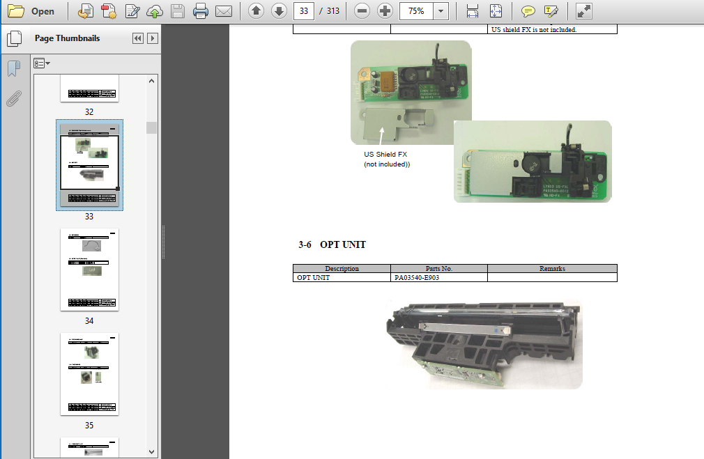
3-6 OPT UNIT 33
3-7 BW MOTOR 34
3-8 GUIDE P ASSY (Sheet Guide) 34
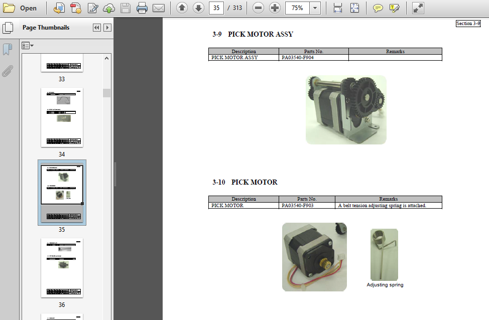
3-9 PICK MOTOR ASSY 35
3-10 PICK MOTOR 35
3-11 PICK SHAFT ASSY 36
3-12 SWITCH (ADF open detection) 36
3-13 UPPER UNIT 37
3-14 UPPER ASSY 37
3-15 ADF MOTOR 38
3-16 (Reserved) 38
3-17 (Reserved) 38
3-18 (Reserved) 38
3-19 US SENSOR RV (Multifeed detection) 38
3-20 SENSOR EMP (Paper empty detection) 39
3-21 PANEL PCA 39
3-22 BR SHAFT ASSY 39
3-23 CONTROL PCA 40
3-24 (Reserved) 41
3-25 STACKER UNIT 41
3-26 CHUTER UNIT (ADF paper chute) 41
3-27 AC ADAPTER 42
3-28 AC CORDSETS 42
08 July 27, 09 K Okada A Miyoshi I Fujioka Refer to Revision Record on page 2
TITLE
fi-6140/fi-6240/fi-6130/fi-6230/fi-614PR
Maintenance Manual
07 Nov 12, 08 K Okada T Anzai I Fujioka Refer to Revision Record on page 2 CUST
06 Mar 10, 08 K Okada T Anzai I Fujioka Refer to Revision Record on page 2
DRAW
No P1PA03540-B0XX/6
Rev DATE DESIGN CHECK APPR DESCRIPTION
Design July 27, 2007 K Okada CHECK K Okada APPR T Anzai PFU LIMITED Page 6 / 257
3-29 USB CABLE 42
3-30 FB TOP COVER 43
3-31 FB MOTOR UNIT 43
3-32 FB MOTOR 44
3-33 OPT BOX UNIT 44
3-34 (Reserved) 44
3-35 (Reserved) 44
3-36 (Reserved) 44
3-37 CR CABLE 45
3-38 DOC COVER ASSY 45
3-39 JOINT PCA 46
6-40 (Reserved) 46
Chapter 4 Troubleshooting 47
4-1 Operation Panel Sequence at Power-on 47
4-2 Temporary errors and Alarm detection algorithm 48
4-2-1 Temporary errors 48
4-2-2 Alarms 48
4-2-3 Error Recovery Guide 48
4-3 Troubleshooting 49
4-3-1 Scanner is not turned ON (Display of the operator panel goes out) 51
4-3-2 Scanning does not start 51
4-3-3 Scanned image is distorted 51
4-3-4 Resolution is not satisfactory or tone error is too large 52
4-3-5 Too much jitter on scanned image with FB scanning fi-6240/fi-6230 52
4-3-6 Scanned image is misaligned with FB scanning fi-6240/fi-6230 53
4-3-7 Scan magnification factor abnormal with FB scanning fi-6240/fi-6230 53
4-3-8 Too much jitter on scanned image with ADF scanning 54
4-3-9 Scanned image is misaligned with ADF scanning 55
4-3-10 Scan magnification factor abnormal with ADF scanning 55
4-3-11 Vertical streaks appear in scanned image 56
4-3-12 When calibrating white of scanned image 56
4-3-13 Frequent “J1: paper jam” error at scanner section 57
4-3-14 Frequent “J2: multi feed error” 58
4-3-15 Error detection of “U4: Scanner Cover open” 58
4-3-16 Error detection of “No paper on the ADF paper chute (Chuter Unit)” 58
4-3-17 Frequent “U0: Shipping lock error” or “E0: Carrier drive alarm” 59
4-3-18 “E1/E2/E3: Optical alarm” 59
4-3-19 “E6: Operator panel alarm” 60
4-3-20 “E7: EEPROM alarm” 60
4-3-21 “E8: SCSI alarm” 60
4-3-22 “E9: Image memory alarm” 60
4-3-23 “F4: Background changeover unit alarm” 61
4-3-24 “C0: LSI alarm” 61
4-3-25 “H0/H8: Motor alarm” 62
4-3-26 “Lamp alarm” 63
4-3-27 “L6: US sensor alarm” 63
4-3-28 “F: ROM sum check alarm” 63
4-3-29 Driver error 63
4-3-30 “Abnormal command” 64
4-3-31 “Interface alarm” 64
4-3-32 Frequent “J1: paper jam” error at Imprinter (with Imprinter installed) fi-6140/fi-6130 64
4-3-33 Error detection of “U5:Imprinter cover open” (with Imprinter installed) fi-6140/fi-6130 64
4-3-34 Imprinter does not initially operate (with Imprinter installed) fi-6140/fi-6130 65
4-3-35 “U6: No print cartridge” (with Imprinter installed) fi-6140/fi-6130 65
4-3-36 “H6: Imprinter fuse blown” (with Imprinter installed) fi-6140/fi-6130 66
4-3-37 “A0: Imprinter control board alarm” (with Imprinter installed) fi-6140/fi-6130 66
“A1: Imprinter communication timeout” (with Imprinter installed) fi-6140/fi-6130 66
“A2: Ink head alarm” (with Imprinter installed) fi-6140/fi-6130 66
“A3: Imprinter EEPROM alarm” (with Imprinter installed) fi-6140/fi-6130 66
“A4: Imprinter ROM alarm” (with Imprinter installed) fi-6140/fi-6130 66
4-3-38 No printing / Printed letters are distorted (with Imprinter installed) fi-6140/fi-6130 67
4-3-39 Print form is dirty (with Imprinter installed) fi-6140/fi-6130 67
4-3-40 Printing is interrupted in process (with Imprinter installed) fi-6140/fi-6130 67
4-3-41 Frequent “J0: paper jam” (paper protection function) fi-6140/fi-6240 68
Chapter 5 Disassembly/Assembly 69
5-1 For the safety operation 69
5-2 Periodic Maintenance 70
5-3 Cleaning 71
5-3-1 OPT Unit (common to ADF front/backside and Flatbed) 71
5-3-2 Glass inside of Base Unit 71
5-3-3 Glass inside of Upper Unit 71
5-3-4 Glass inside of Flatbed fi-6240/fi-6230 72
5-3-5 White reference inside of Base Unit 72
5-3-6 White reference inside of Upper Unit 72
5-4 Maintenance tool 73
5-5 Parts that should not be Disassembled 74
5-6 (Reserved) 74
5-7 Removing Flatbed fi-6240/fi-6230 75
5-8 Chuter Unit (ADF Paper Chute), Stacker Unit 77
5-8-1 Chuter Unit (ADF Paper Chute) 77
5-8-2 Stacker Unit fi-6140/fi-6130 78
5-9 Base Unit 79
5-9-1 Base Unit 79
5-9-2 Base ASSY 84
5-9-3 Inverter (for front side scanning) 85
5-9-4 Lamp (for front side scanning) 87
5-9-5 US Sensor FX (Multifeed detection) 93
5-9-6 OPT Unit (for front side scanning) 96
5-9-7 BW Motor 98
5-9-8 Guide P ASSY (Sheet Guide) 100
5-9-9 PICK Motor ASSY 101
5-9-10 PICK Motor 103
5-9-11 PICK Shaft ASSY 105
5-9-12 Switch (ADF open detection) 106
5-10 Upper Unit 107
5-10-1 Upper Unit 107
5-10-2 Upper ASSY 108
5-10-3 ADF Motor 109
5-10-4 OPT Unit (for backside scanning) 112
5-10-5 Inverter (for backside scanning) 114
5-10-6 Lamp (for backside scanning) 116
5-10-7 US Sensor RV (Multifeed detection) 123
5-10-8 Sensor EMP (Paper empty detection) 124
5-10-9 Panel PCA 125
5-10-10 BR Shaft ASSY 127
5-10-11 Top Cover 128
5-11 Control PCA 130
08 July 27, 09 K Okada A Miyoshi I Fujioka Refer to Revision Record on page 2
fi-6140/fi-6240/fi-6130/fi-6230/fi-614PR
Maintenance Manual
07 Nov 12, 08 K Okada T Anzai I Fujioka Refer to Revision Record on page 2 CUST
06 Mar 10, 08 K Okada T Anzai I Fujioka Refer to Revision Record on page 2
DRAW
No P1PA03540-B0XX/6
Rev DATE DESIGN CHECK APPR DESCRIPTION
Design July 27, 2007 K Okada CHECK K Okada APPR T Anzai PFU LIMITED Page 8 / 257
5-12 Flatbed 133
5-12-1 FB Top Cover fi-6240/fi-6230 133
5-12-2 FB Motor Unit fi-6240/fi-6230 134
5-12-3 FB Motor fi-6240/fi-6230 138
5-12-4 OPT Box Unit fi-6240/fi-6230 140
5-12-5 OPT Unit fi-6240/fi-6230 143
5-12-6 Inverter fi-6240/fi-6230 145
5-12-7 Lamp fi-6240/fi-6230 147
5-12-8 CR Cable fi-6240/fi-6230 150
5-12-9 Document Cover fi-6240/fi-6230 153
5-12-10 Joint PCA fi-6240/fi-6230 154
Chapter 6 Adjustment/Settings 156
6-1 Maintenance mode 156
6-1-1 Activating the Maintenance mode 156
6-1-2 Maintenance mode #1: Paper feeding / Sensor / Background changeover test 158
6-1-3 Maintenance mode #2: Main scanning / Sub-scanning magnification adjustment 160
6-1-4 Maintenance mode #3: Offset adjustment 164
6-1-5 Maintenance mode #4: White level adjustment 167
6-1-6 Maintenance mode #5: Consumable counter display and reset 170
6-1-7 Maintenance mode #6: Miscellaneous information display 172
6-1-8 Maintenance mode #7: EEPROM data restore 174
6-2 Saving EEPROM data 175
Chapter 7 Basic Operation and Daily Care 177
7-1 Basic Operation 177
7-1-1 Turn ON/OFF the Scanner 177
7-1-2 Loading Documents on the ADF for Scanning 178
7-1-3 Loading Documents on the Flatbed for Scanning fi-6240/fi-6230 181
7-2 Daily Care 182
7-2-1 Cleaning the ADF 182
7-2-2 Cleaning the Flatbed fi-6240/fi-6230 185
7-3 Replacing the consumables 186
7-3-1 Consumables 186
7-3-2 Checking and Resetting the Consumables Counters 187
7-3-3 Brake roller replacement 189
7-3-4 Pick roller replacement 191
Chapter 8 Imprinter (Optional) 194
8-1 Imprinter Specifications 194
8-1-1 Printing Functions 194
8-1-2 Environmental Specifications 195
8-1-3 Appearance 196
8-1 Imprinter Operation 198
8-2-1 Imprinter Operation 198
8-2-2 Circuit Block Diagram 199
8-3 Unpacking and Installation of Imprinter 200
8-3-1 Unpacking the Imprinter 200
8-3-2 Installing the Imprinter 201
8-3-3 Loading the Print cartridge 203
8-3-4 Operation Test 205
8-4 Maintenance Parts for the Imprinter 206
8-4-1 SENSOR 207
8-4-2 IMP CT 207
8-4-3 IMP JNT 208
8-4-4 PR HARNESS 208
8-4-5 IM FELT 209
8-4-6 LF MOTOR 209
8-4-7 IM HOLDER ASSY3 210
8-4-8 IM HOLD LEVER3 210
8-4-9 FPC CABLE 211
8-4-10 IM PINCH ASSY3 211
8-4-11 IM LOCK LEVER 212
8-4-12 SWITCH (Cover open detection) 212
8-4-13 GUIDE SHEET 213
8-4-14 PAPER GUIDE3 213
8-5 Troubleshooting 214
8-6 Disassembly/Assembly 215
8-6-1 For Safety operation 215
8-6-2 Maintenance tool 215
8-6-3 (Reserved) 215
8-6-4 Removing Imprinter 216
8-6-5 IM HOLD LEVER3 217
8-6-6 IM PINCH ASSY3 218
8-6-7 IMP JNT 221
8-6-8 IM HOLDER ASSY3/FPC CABLE 223
8-6-9 IMP CT 225
8-6-10 SENSOR 227
8-6-11 SWITCH (Cover open detection) 230
8-6-12 LF MOTOR 232
8-6-13 PR HARNESS 235
8-6-14 IM FELT 236
8-6-15 IM LOCK LEVER 238
8-6-16 GUIDE SHEET 239
8-7 Adjustment/Settings 240
8-8 Basic Operation and Daily Care of the Imprinter 241
8-8-1 Setting The Print Position 241
8-8-2 How to Use the Paper Guides 242
8-8-3 Print Setup 244
8-8-4 Removing Jammed Documents 247
8-9 Cleaning and Consumables 248
8-9-1 Cleaning the Print Cartridge 248
8-9-2 Cleaning the Imprinter 249
8-9-3 Cleaning the Imprinter Rollers 250
8-9-4 Replacing the Print Cartridge 251
Appendix 1 Screws 253
Appendix 2 Emulation Mode 255
SCREENSHOT OF THE MANUAL:


VIDEO PREVIEW:
PLEASE NOTE:
⦁ This is the SAME exact manual used by your dealers to fix your vehicle.
⦁ The same can be yours in the next 2-3 mins as you will be directed to the download page immediately after paying for the manual.
⦁ Any queries / doubts regarding your purchase, please feel free to contact [email protected]


